Abstract
Dual-energy CT (DECT) is an exciting innovation in CT technology with profound capabilities to improve diagnosis and add value to patient care. Significant advances in this technology over the past decade have improved our ability to successfully adopt DECT into the clinical routine. To enable effective use of DECT, one must be aware of the pitfalls and artifacts related to this technology. Understanding the underlying technical basis of artifacts and the strategies to mitigate them requires optimization of scan protocols and parameters. The ability of radiologists and technologists to anticipate their occurrence and provide recommendations for proper selection of patients, intravenous and oral contrast media, and scan acquisition parameters is key to obtaining good-quality DECT images. In addition, choosing appropriate reconstruction algorithms such as image kernel, postprocessing parameters, and appropriate display settings is critical for preventing quantitative and qualitative interpretive errors. Therefore, knowledge of the appearances of these artifacts is essential to prevent errors and allows maximization of the potential of DECT. In this review article, the authors aim to provide a comprehensive and practical overview of possible artifacts that may be encountered at DECT across all currently available commercial clinical platforms. They also provide a pictorial overview of the diagnostic pitfalls and outline strategies for mitigating or preventing the occurrence of artifacts, when possible. The broadening scope of DECT applications necessitates up-to-date familiarity with these technologies to realize their full diagnostic potential.
An invited commentary by Szczykutowicz is available online.
©RSNA, 2021
An earlier incorrect version of this article appeared online and in print. This article was corrected on March 1st, 2021.
SA-CME LEARNING OBJECTIVES
After completing this journal-based SA-CME activity, participants will be able to:
■ Describe the technical principles, strengths, and limitations of different types of DECT scanners.
■ Understand when to anticipate artifacts and how to implement protocols for preventing their occurrence.
■ Discuss strategies for postprocessing good-diagnostic-quality DECT images by optimizing thresholding and kernel parameters.
Introduction
Dual-energy CT (DECT)—also known as multienergy CT or spectral CT—has utility in a wide range of routine and advanced clinical applications in diagnostic radiology. By enabling separate acquisition of two energy spectra, DECT allows reconstruction of valuable images that provide information beyond what is possible with conventional single-energy CT (SECT). The benefits of DECT-derived images include the ability to (a) characterize materials, thereby enabling improved lesion detection and characterization; (b) permit more robust quantitation; (c) reduce the volume of iodinated contrast medium; (d) limit radiation dose; and (e) reduce artifacts. These advantages enable DECT to improve diagnostic confidence and allow superior assessment of incidental lesions, thereby reducing follow-up and additional imaging or procedures and decreasing institutional costs (1,2).
Artifacts at imaging are false perceptions and representations of structures that are not present in reality but are seen on the images. At CT, they are a manifestation of variance in attenuation between the true attenuation coefficient of an object in projection space versus on a reconstructed CT image (3). They can degrade images and render them nondiagnostic or spuriously mask or simulate anatomic and pathologic structures, leading to erroneous interpretation.
Although artifacts are generally less prevalent and less severe in CT than in other cross-sectional imaging modalities, a multitude of artifacts are encountered on SECT images and appear as streaks, blurs, rings, or stripes. A few of these include beam-hardening, photon starvation, and motion-related artifacts (3). While DECT has been explored for mitigating metal-related beam-hardening artifacts (4), some of these CT artifacts also affect DECT and impact material decomposition. Moreover, DECT-derived images are susceptible to some artifacts that are inherent to this technology owing to the scanner design, acquisition parameters, postprocessing technique, and image display.
As DECT is being increasingly incorporated into clinical practice and guidelines (5), it is essential for radiologists to be familiar with artifacts that may cause diagnostic uncertainties during image interpretation. In this article, we provide a comprehensive overview of artifacts and pitfalls that may be encountered in DECT across currently available commercial clinical DECT platforms and discuss ways to recognize them and mitigate or prevent them, when possible.
DECT Technologies
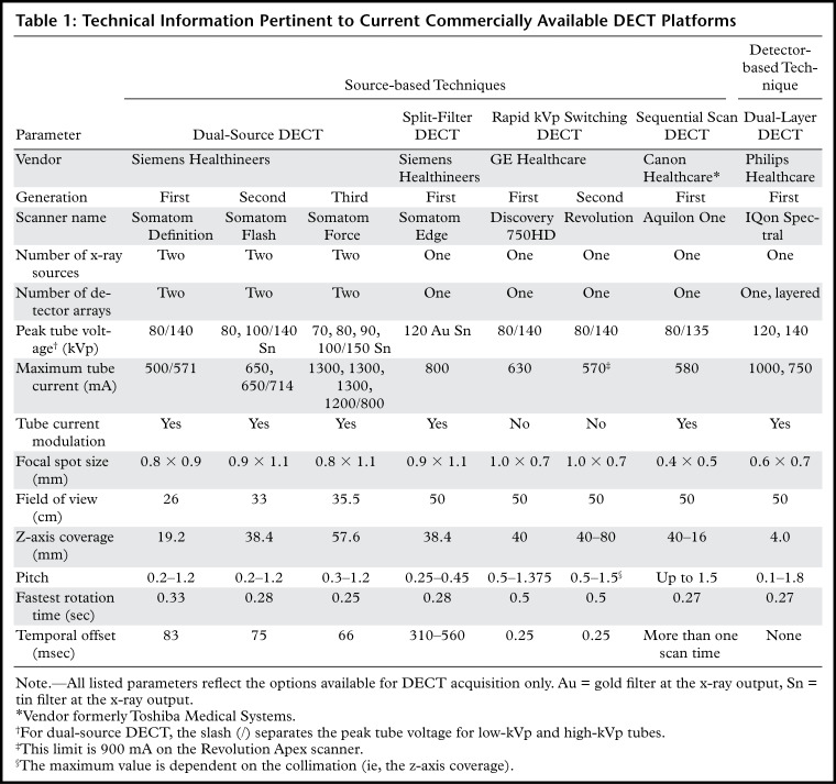
Currently available DECT technologies can be broadly classified as source based or detector based (6). An overview of these DECT approaches is presented in Table 1.
Table 1:
Technical Information Pertinent to Current Commercially Available DECT Platforms
The following four DECT technologies are source based: Dual-source DECT has two x-ray tubes with corresponding detectors that are perpendicular to each other, and the x-ray tubes operate at two different voltages (6). In rapid tube voltage (kilovolt peak [kVp]) switching DECT, the peak voltage of the x-ray tube rapidly alternates between high and low energies for each x-ray projection (6). In split-filter DECT, a filter composed of gold (low energy) and tin (high energy) in the z direction splits the x-ray beam into two "effective" beams with different mean energies (6). In dual-spin DECT, the patient undergoes two consecutive acquisitions at different tube voltages in either a sequential or helical mode (6).
Dual-layer DECT is the only commercially available detector-based technology to date. It has a single x-ray tube and two layers of detectors, wherein the top layer (yttrium-based garnet) absorbs low-energy photons and the bottom layer (gadolinium oxysulfide) absorbs high-energy photons (6). Photon-counting DECT, a detector-based technique still in the research phase, has a semiconductor detector that directly converts x-ray photons into electrical signals, which are assigned to specific energy bins, thus providing true multienergy capability (6).
Images
Unlike SECT, DECT allows generation of a wide range of image datasets with varied information and material-specific properties. Besides differences in acquisition, the different DECT technologies also vary in their image reconstruction approach, that is, either in the image domain (dual-source DECT, split-filter DECT, helical mode of dual-spin DECT) or in the projection domain (rapid kVp switching DECT, dual-layer DECT). In the projection domain, reconstruction algorithms are applied to projection data that are directly obtained from the scan acquisition and can therefore be applied only when the low- and high-energy data are aligned temporally and spatially. In the image-based domain, reconstruction algorithms are applied to images after they have been reconstructed.
Nevertheless, all platforms yield images that show similar characteristics, albeit with varying nomenclature. The most common DECT images include the following: (a) images similar to conventional SECT images (ie, 120 kVp–like images); (b) virtual monochromatic (VMC) or monoenergetic images at a range of kilo–electron volt (keV) levels; (c) material density (MD) images, which selectively display the material in question (most commonly iodine, urate, or calcium) in gray scale or with color overlay; and (d) virtual noncontrast (VNC) and virtual noncalcium (VNCa) images, on which selected materials like iodine and calcium are selectively suppressed (6).
Pitfalls Related to DECT Acquisition, Postprocessing, and Display
DECT Acquisition
Generation of high-quality diagnostic DECT images with maximum spectral information depends on several factors, such as patient characteristics, acquisition protocol, and postprocessing parameters. Additionally, certain DECT approaches and techniques make them prone to artifacts unique to the DECT platform that cannot be overcome by optimizing scan parameters. The goal is to choose a DECT scan protocol that provides an optimal balance among radiation dose, image quality, and spectral separation.
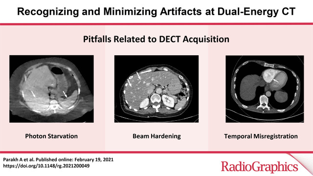
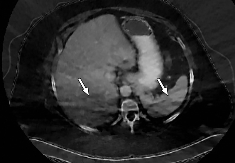
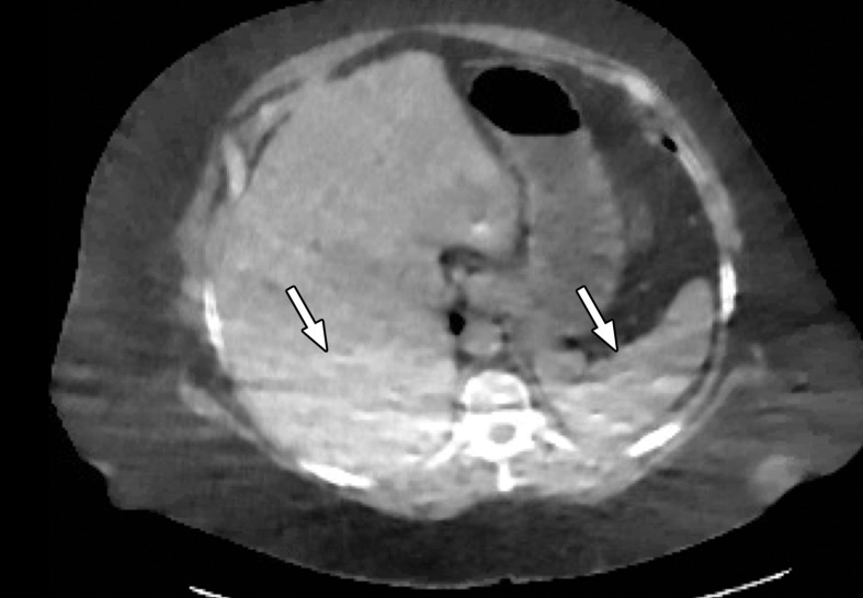
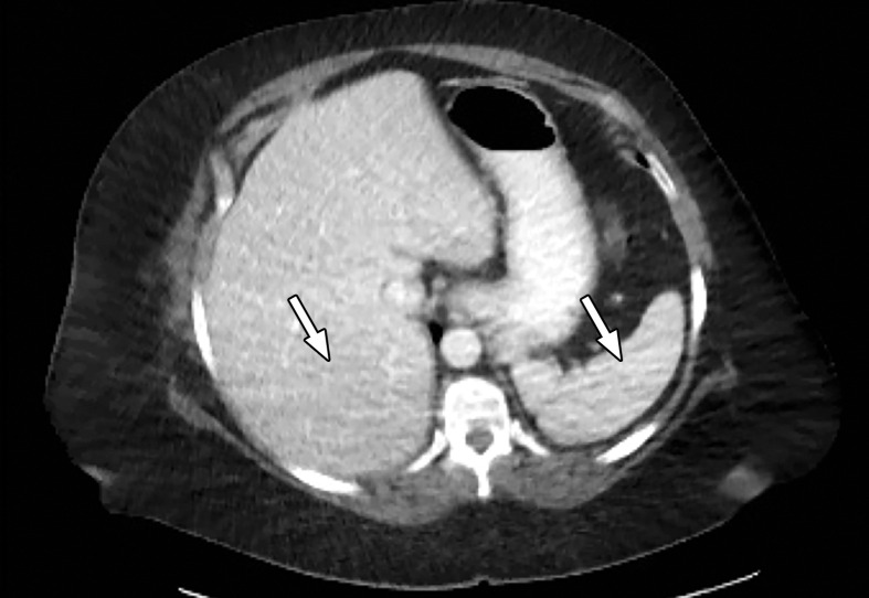
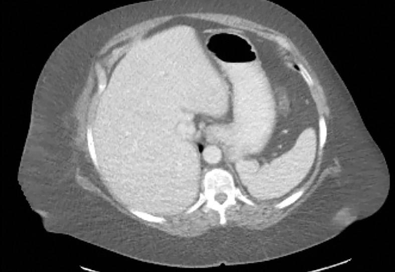
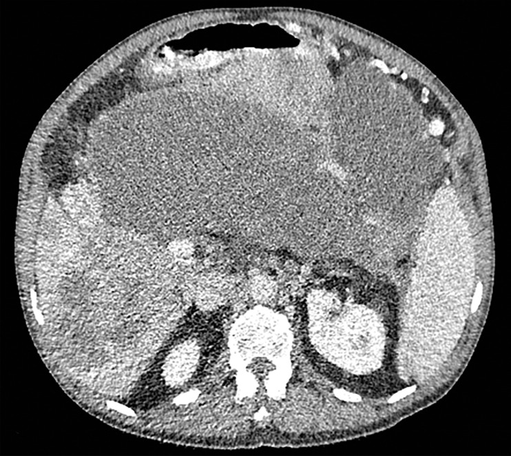
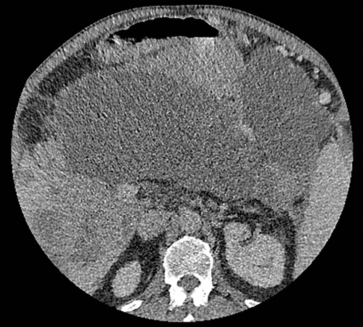
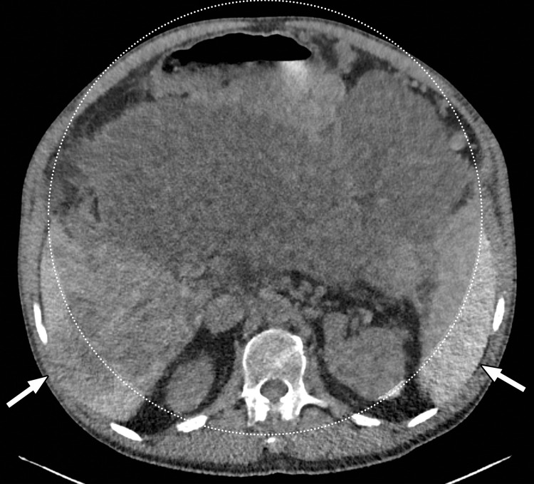
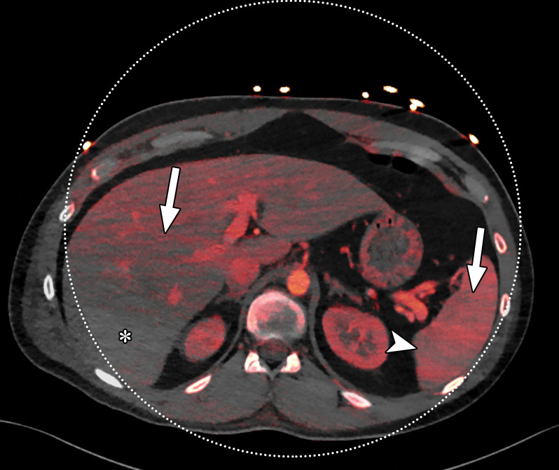
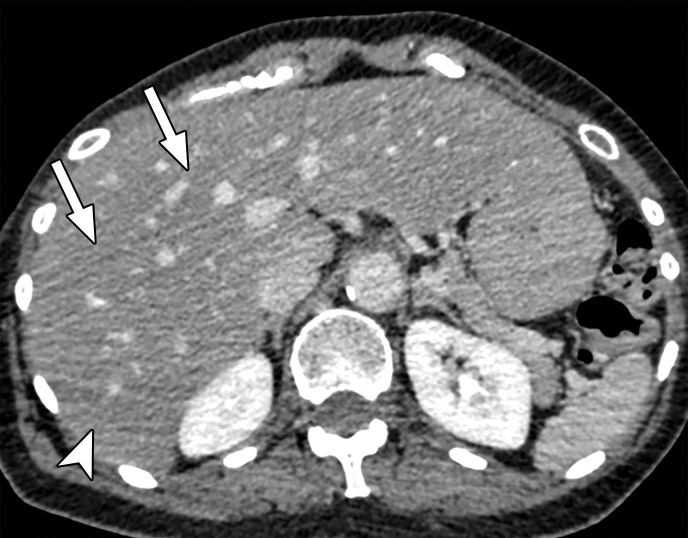
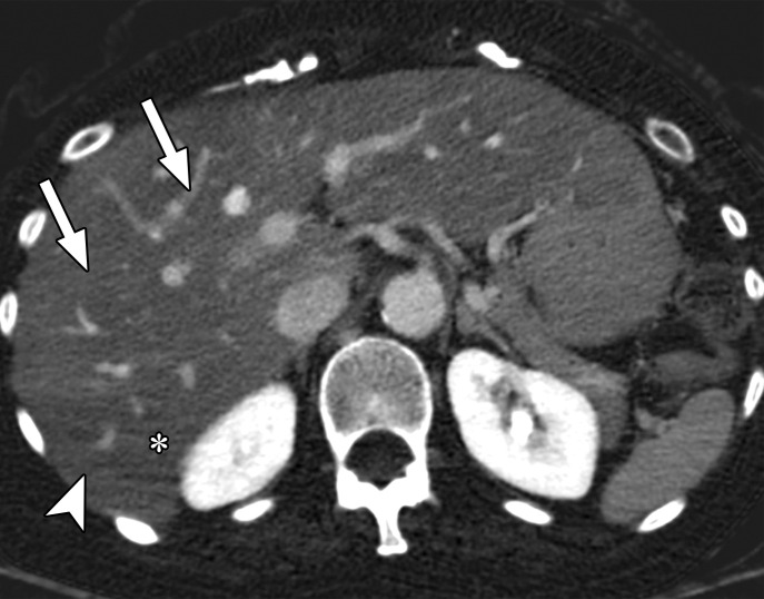
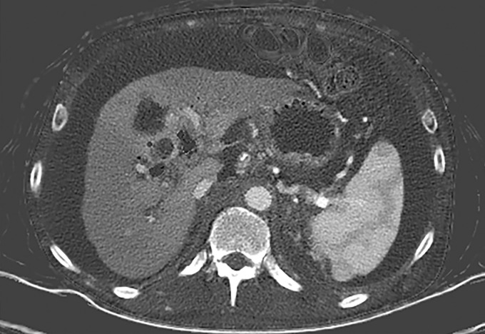
Patient Selection.—Optimization of protocols based on patient factors such as body weight and transverse diameter is crucial for acquiring diagnostic-quality images at DECT (7). In patients with large body habitus, DECT may yield higher image noise and reduced image quality due to photon starvation (Fig 1) (8,9). This occurs because an insufficient number of photons reach the detectors and affects the quality of all DECT images. A particular concern in patients with large body habitus is the impact on material decomposition and tissue characterization. For example, a commonly reported pitfall is reduced specificity for determining stone composition in calculi smaller than 3 mm in these patients (10). However, separate phantom and clinical investigations have demonstrated that patient size does not affect material separation for lesions of clinically significant size such as calculi larger than 3 mm (11–14). A consensus panel has recommended weight (260–280 lb [118–127 kg]) and transverse diameter (38–46 cm) cutoff values for selecting patients who are suitable for undergoing DECT of the abdomen (7). Several strategies including modification of acquisition parameters can also be implemented to improve image quality and maximize the potential of DECT in this population.
Figure 1a.
Photon starvation in a large patient. Axial portovenous phase abdominopelvic CT was performed in a 242-lb (110-kg) patient using rapid kilovolt peak (kVp) switching DECT. (a) Material density (MD)–iodine image shows dark bands of artifact (arrows) across the liver and spleen. (b) On an MD-water image, the streaks appear as bright bands (arrows). (c) On a 65 kilo–electron volt (keV) image, the artifacts are much less apparent (arrows). (d) On a 140 kVp–equivalent image, the artifacts are not visualized.
Figure 1b.
Photon starvation in a large patient. Axial portovenous phase abdominopelvic CT was performed in a 242-lb (110-kg) patient using rapid kilovolt peak (kVp) switching DECT. (a) Material density (MD)–iodine image shows dark bands of artifact (arrows) across the liver and spleen. (b) On an MD-water image, the streaks appear as bright bands (arrows). (c) On a 65 kilo–electron volt (keV) image, the artifacts are much less apparent (arrows). (d) On a 140 kVp–equivalent image, the artifacts are not visualized.
Figure 1c.
Photon starvation in a large patient. Axial portovenous phase abdominopelvic CT was performed in a 242-lb (110-kg) patient using rapid kilovolt peak (kVp) switching DECT. (a) Material density (MD)–iodine image shows dark bands of artifact (arrows) across the liver and spleen. (b) On an MD-water image, the streaks appear as bright bands (arrows). (c) On a 65 kilo–electron volt (keV) image, the artifacts are much less apparent (arrows). (d) On a 140 kVp–equivalent image, the artifacts are not visualized.
Figure 1d.
Photon starvation in a large patient. Axial portovenous phase abdominopelvic CT was performed in a 242-lb (110-kg) patient using rapid kilovolt peak (kVp) switching DECT. (a) Material density (MD)–iodine image shows dark bands of artifact (arrows) across the liver and spleen. (b) On an MD-water image, the streaks appear as bright bands (arrows). (c) On a 65 kilo–electron volt (keV) image, the artifacts are much less apparent (arrows). (d) On a 140 kVp–equivalent image, the artifacts are not visualized.
Photon starvation and quantum mottle are more likely at low kVp, as fewer photons reach the detector, causing increased image noise. Therefore, this more apparently affects DECT platforms where the low-kVp option is limited to 80 kVp (eg, rapid kVp switching DECT or dual-source DECT when the low-energy tube operates at 70 or 80 kVp) (Table 1). This can be mitigated at rapid kVp switching DECT by choosing an optimal vendor-specific parameter called the Gemstone Spectral Imaging (GSI) preset.
The variables included in this preset include focal spot size, collimation, rotation time, pitch, and tube current; it also provides an estimated volumetric CT dose index. Choosing a preset with higher tube current, slower rotation time, and lower pitch can increase the photon flux (15,16) and thus improve image quality. However, higher tube current comes at the expense of higher radiation dose; it is important to note that, by virtue of this platform’s hardware design, tube current modulation is not possible to curtail the radiation dose.
A recent technical development in this regard is that the latest rapid kVp switching DECT scanner models are equipped with a new x-ray tube that enables synchronous switching of tube current according to tube voltage state, so that higher tube current is applied at a low-kVp state (80 kVp) and lower tube current is applied at a high-kVp state (140 kVp). However, the tube current does not modulate along the craniocaudal axis. This approach has the potential to reduce photon starvation at low-kVp projections while being radiation-dose efficient and be useful in imaging large patients. However, clinical studies have yet to be done to investigate its performance.
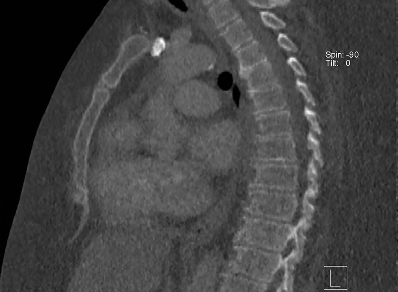
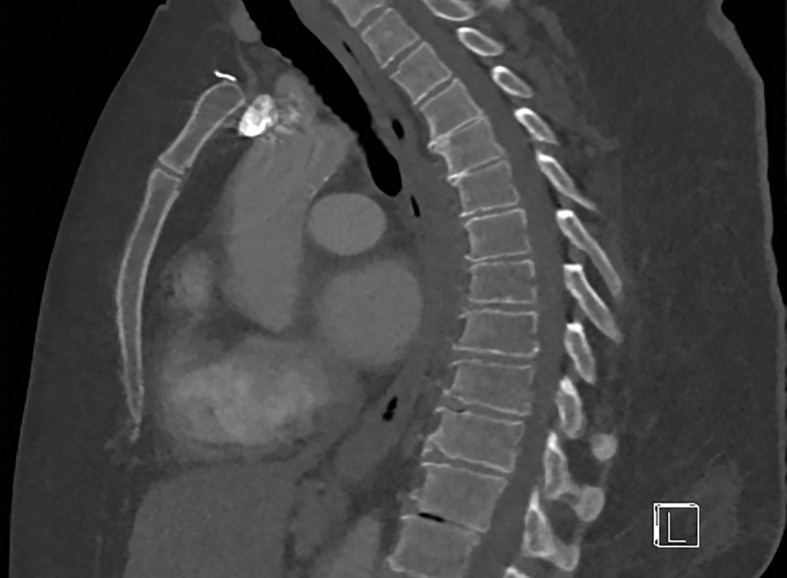
At dual-source DECT, the low-energy tube can be operated at 100 kVp to ensure improved penetration of the low-energy beam (Fig 2) (17). However, a higher low-kVp beam improves image quality at the cost of a larger degree of spectral overlap and higher radiation dose. Use of a tin filter (Sn) at the output of the high-energy tube hardens the beam by removing low-energy photons, which contribute more to image noise and little to diagnostic information, diminishing the degree of spectral overlap. Furthermore, the ability to modulate tube current prevents a significant increase in radiation dose. The limitation for large patients that cannot be altered by changing scan protocol on this platform is related to spectral field of view (FOV) restriction, which is discussed in the "Patient Positioning" section.
Figure 2a.
Importance of protocol selection. Sagittal single-energy–equivalent CT images of the thorax in a 280-lb (127-kg) patient, obtained with dual-source DECT at the same window display setting at two time points. The images were acquired at tube voltages of 80/140 kVp tin filter (Sn) (volumetric CT dose index = 10 mGy) (a) and 100/150 kVp Sn (volumetric CT dose index = 25 mGy) (b). Image quality is superior in b compared with in a owing to improved photon flux and penetration, at the expense of higher radiation dose.
Figure 2b.
Importance of protocol selection. Sagittal single-energy–equivalent CT images of the thorax in a 280-lb (127-kg) patient, obtained with dual-source DECT at the same window display setting at two time points. The images were acquired at tube voltages of 80/140 kVp tin filter (Sn) (volumetric CT dose index = 10 mGy) (a) and 100/150 kVp Sn (volumetric CT dose index = 25 mGy) (b). Image quality is superior in b compared with in a owing to improved photon flux and penetration, at the expense of higher radiation dose.
Body habitus does not impact image quality and material decomposition at dual-layer DECT, where 70-keV virtual monochromatic images were in fact preferred to 120-kVp images by radiologists and the majority of the MD-iodine images were deemed diagnostically acceptable (18) as long as radiation dose was not compromised (19,20). Nevertheless, the x-ray tube can be operated at 140 kVp in dual-layer DECT to improve image quality, with the advantage of improved spectral separation (21). Iterative reconstruction techniques employed by the different DECT platforms may further improve image quality in large patients across all platforms by reducing image noise.
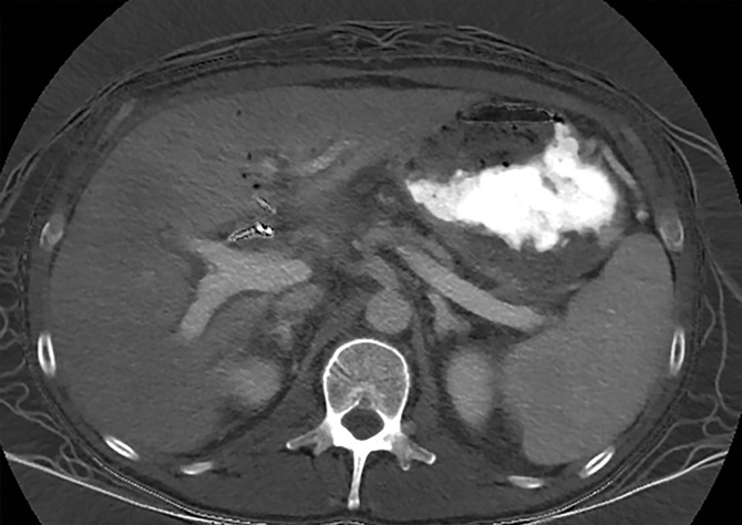
Contrast Medium (Intravenous or Oral) Selection.—Iodine density is higher on low-keV virtual monochromatic images owing to the k-edge of iodine (33.2 keV). Therefore, significant amplification of iodinated contrast medium (intravenous or oral) can occur on low-keV and MD-iodine images at the concentration and volumes used in routine SECT. This "blooming" of iodine, especially in oral contrast medium–filled bowel loops, can cause streaks across the image and hinder visualization of adjacent disease or obscure evaluation of bowel folds.
While changing the window width (WW) and window level (WL) settings can mitigate these artifacts to a certain degree, reduction of iodine concentration is often necessary. Reducing intravenous and oral contrast medium concentration is a potential solution for diminishing contrast medium–related streak artifacts without affecting diagnostic performance for vascular and nonvascular applications in different body regions (22–24). Reducing the iodinated concentration of contrast medium may also help improve the quality of VNC images, as venous phase–derived VNC images have lower residual iodine than arterial phase–derived VNC images (24).
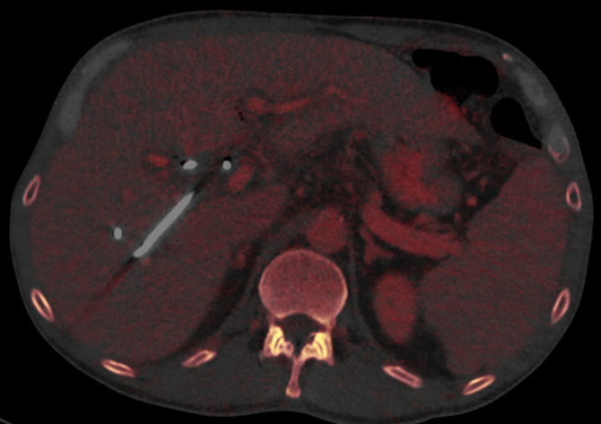
One of the benefits of DECT is the ability to identify contrast medium extravasation in patients with suspected gastrointestinal bleeding, without the need for true noncontrast (TNC) acquisition. Iodine within the bowel lumen is due to either extravasation of intravenously injected contrast medium or retained oral contrast medium. Both of these are visualized on MD-iodine images and removed on VNC images; hence, it may be difficult to distinguish between the two. Moreover, both barium and iodine have similar attenuation profiles and cannot be separated with DECT. As of now, when clinical suspicion of a gastrointestinal bleed is high, positive oral contrast medium should be avoided and TNC acquisition may still be necessary for diagnosis. Delayed phase images also demonstrate an increase in the volume of bleed to assist in making this diagnosis (25).
DECT also provides avenues for using multi–contrast media imaging with novel CT contrast agents like gadolinium, tantalum, bismuth, and tungsten as adjuncts to iodine. MD images from DECT can selectively remove or depict different contrast media and provide material-specific maps. DECT can thus provide multiphase information from a single acquisition (26,27). The aforementioned agents, other than gadolinium and iodine, are not yet approved by the U.S. Food and Drug Administration and are still being explored in small and large animal studies.
Patient Positioning.—The term spectral FOV refers to the area for which multienergy information can be processed. In dual-source DECT, the detector array associated with the high-kVp x-ray tube covers a smaller FOV (26–35.5 cm, depending on the scanner generation [Table 1]) than the detector array associated with the low-kVp tube (50 cm). This constrains the spectral FOV but not the conventional FOV, as DECT information—with data from both tubes—is available only for the overlapping area.
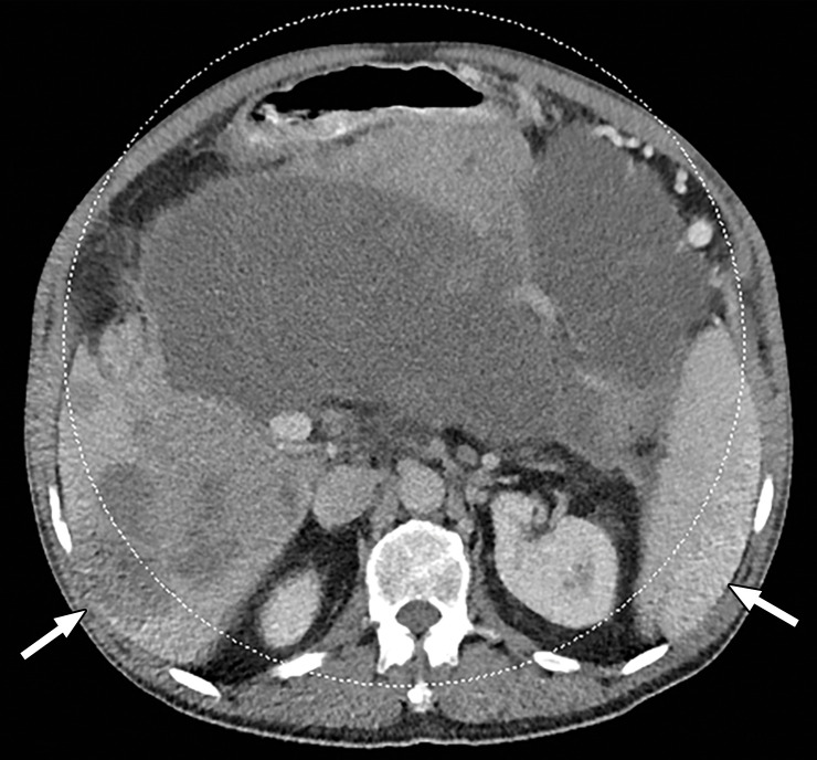
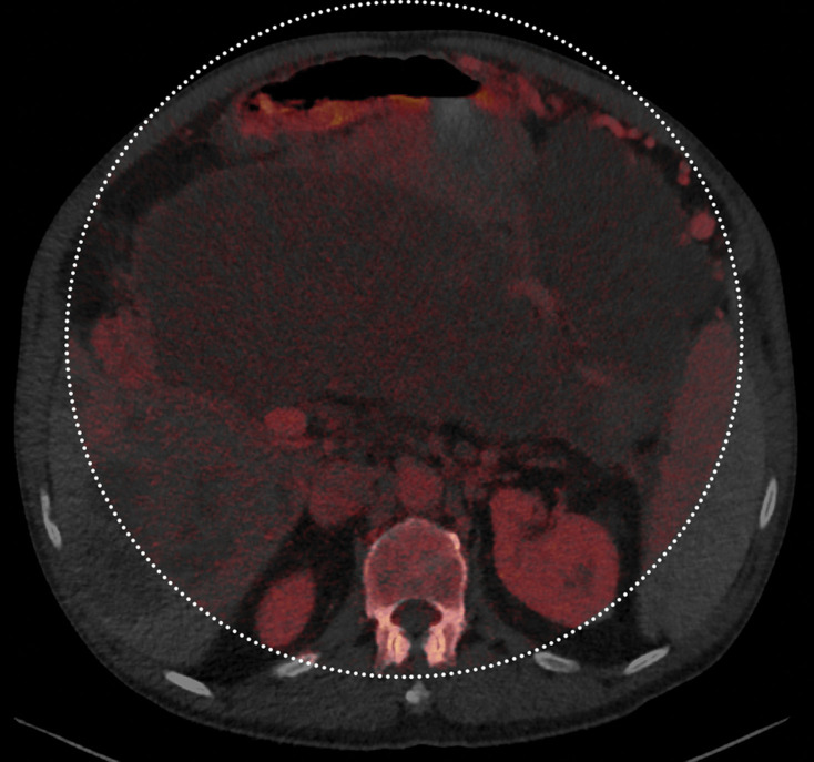
The anatomic area that lies outside the spectral FOV can have degraded image quality on single-energy–equivalent DECT images (Fig 3), since these are projections from the low-kVp tube. Qualitative and quantitative material decomposition analysis is also not possible for these areas, and on VNC images, these regions can have spurious higher attenuation. The limits of the spectral FOV are depicted on axial images as an interrupted circle, so that radiologists can identify the area for which spectral postprocessing is possible.
Figure 3a.
Constrained spectral field of view (FOV). Axial abdominopelvic CT images obtained in a 233-lb (106-kg) patient with a second-generation dual-source DECT scanner. (a, b) Image acquired at 100 kVp (a) has a larger FOV (50 cm) than an image acquired at 140 kVp Sn (33 cm) (b) owing to a difference in associated detector size. (c) Single-energy–equivalent image shows that the high-kVp tube-detector constrains the spectral FOV, which is limited to the area within the dotted circle, and also degrades the image quality of structures that lie outside the spectral FOV (arrows). (d) On a color overlay MD-iodine image, the constrained spectral FOV limits the anatomic area (within the dotted circle) for which qualitative and quantitative material-specific information (eg, iodine distribution) can be obtained. (e) On a virtual noncontrast (VNC) image, the areas outside the spectral FOV (dotted circle) show spurious high attenuation (arrows).
Figure 3b.
Constrained spectral field of view (FOV). Axial abdominopelvic CT images obtained in a 233-lb (106-kg) patient with a second-generation dual-source DECT scanner. (a, b) Image acquired at 100 kVp (a) has a larger FOV (50 cm) than an image acquired at 140 kVp Sn (33 cm) (b) owing to a difference in associated detector size. (c) Single-energy–equivalent image shows that the high-kVp tube-detector constrains the spectral FOV, which is limited to the area within the dotted circle, and also degrades the image quality of structures that lie outside the spectral FOV (arrows). (d) On a color overlay MD-iodine image, the constrained spectral FOV limits the anatomic area (within the dotted circle) for which qualitative and quantitative material-specific information (eg, iodine distribution) can be obtained. (e) On a virtual noncontrast (VNC) image, the areas outside the spectral FOV (dotted circle) show spurious high attenuation (arrows).
Figure 3c.
Constrained spectral field of view (FOV). Axial abdominopelvic CT images obtained in a 233-lb (106-kg) patient with a second-generation dual-source DECT scanner. (a, b) Image acquired at 100 kVp (a) has a larger FOV (50 cm) than an image acquired at 140 kVp Sn (33 cm) (b) owing to a difference in associated detector size. (c) Single-energy–equivalent image shows that the high-kVp tube-detector constrains the spectral FOV, which is limited to the area within the dotted circle, and also degrades the image quality of structures that lie outside the spectral FOV (arrows). (d) On a color overlay MD-iodine image, the constrained spectral FOV limits the anatomic area (within the dotted circle) for which qualitative and quantitative material-specific information (eg, iodine distribution) can be obtained. (e) On a virtual noncontrast (VNC) image, the areas outside the spectral FOV (dotted circle) show spurious high attenuation (arrows).
Figure 3d.
Constrained spectral field of view (FOV). Axial abdominopelvic CT images obtained in a 233-lb (106-kg) patient with a second-generation dual-source DECT scanner. (a, b) Image acquired at 100 kVp (a) has a larger FOV (50 cm) than an image acquired at 140 kVp Sn (33 cm) (b) owing to a difference in associated detector size. (c) Single-energy–equivalent image shows that the high-kVp tube-detector constrains the spectral FOV, which is limited to the area within the dotted circle, and also degrades the image quality of structures that lie outside the spectral FOV (arrows). (d) On a color overlay MD-iodine image, the constrained spectral FOV limits the anatomic area (within the dotted circle) for which qualitative and quantitative material-specific information (eg, iodine distribution) can be obtained. (e) On a virtual noncontrast (VNC) image, the areas outside the spectral FOV (dotted circle) show spurious high attenuation (arrows).
Figure 3e.
Constrained spectral field of view (FOV). Axial abdominopelvic CT images obtained in a 233-lb (106-kg) patient with a second-generation dual-source DECT scanner. (a, b) Image acquired at 100 kVp (a) has a larger FOV (50 cm) than an image acquired at 140 kVp Sn (33 cm) (b) owing to a difference in associated detector size. (c) Single-energy–equivalent image shows that the high-kVp tube-detector constrains the spectral FOV, which is limited to the area within the dotted circle, and also degrades the image quality of structures that lie outside the spectral FOV (arrows). (d) On a color overlay MD-iodine image, the constrained spectral FOV limits the anatomic area (within the dotted circle) for which qualitative and quantitative material-specific information (eg, iodine distribution) can be obtained. (e) On a virtual noncontrast (VNC) image, the areas outside the spectral FOV (dotted circle) show spurious high attenuation (arrows).
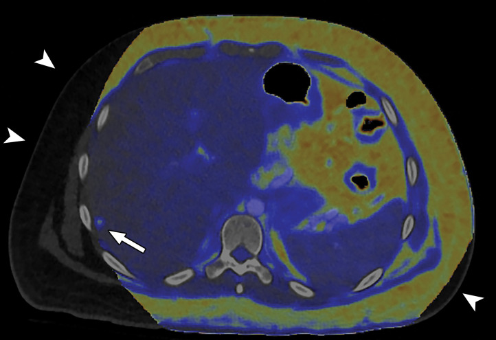
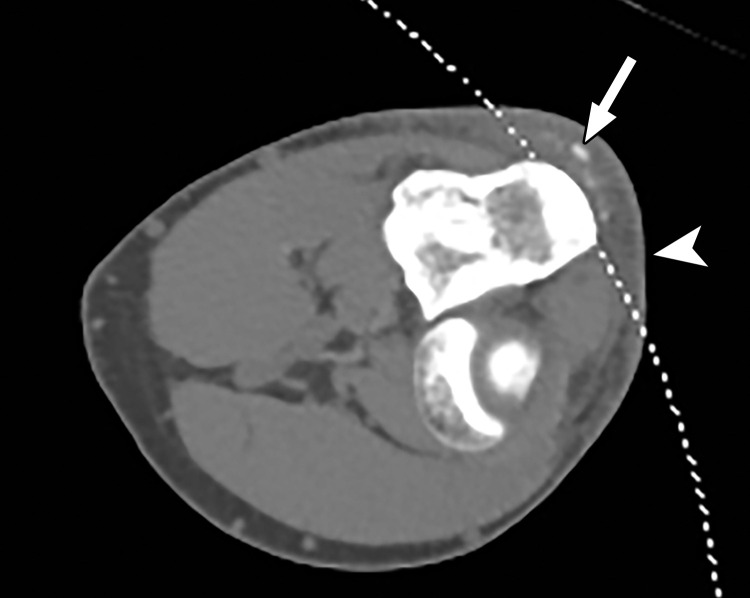
When a patient with body mass index in the normal range is perfectly positioned at the isocenter for an abdominopelvic CT acquisition, the edges of the liver and spleen can lie outside of the spectral FOV. Patients may need to be purposely off centered (28) to ensure that the organ of interest lies completely within the spectral FOV (Fig 4). Although this is intuitively relevant in large patients with a transverse diameter greater than 40 cm undergoing scanning of large anatomic regions like abdominopelvic CT (17), it is equally important for technologists to remain careful when scanning small parts (Fig 5). All other currently available commercial DECT approaches have a full 50-cm spectral FOV.
Figure 4a.
Constrained spectral FOV for the abdomen. Axial portovenous phase dual-source DECT images in a 20-year-old man with tuberous sclerosis. (a) Color overlay MD-fat image shows an 8-mm liver lesion (arrow) just within the limits of the spectral FOV. The limits of the FOV are sharply demarcated, and patient anatomy outside the field (arrowheads) is not color coded (ie, has no spectral information). (b) MD-iodine image shows no iodine uptake qualitatively or quantitatively (0.2 mg/mL) within the lesion (arrow), and quantitation confirms the presence of fat (75%), suggestive of angiomyolipoma. Material analysis of the lesion was possible because it lay within the spectral FOV.
Figure 5.
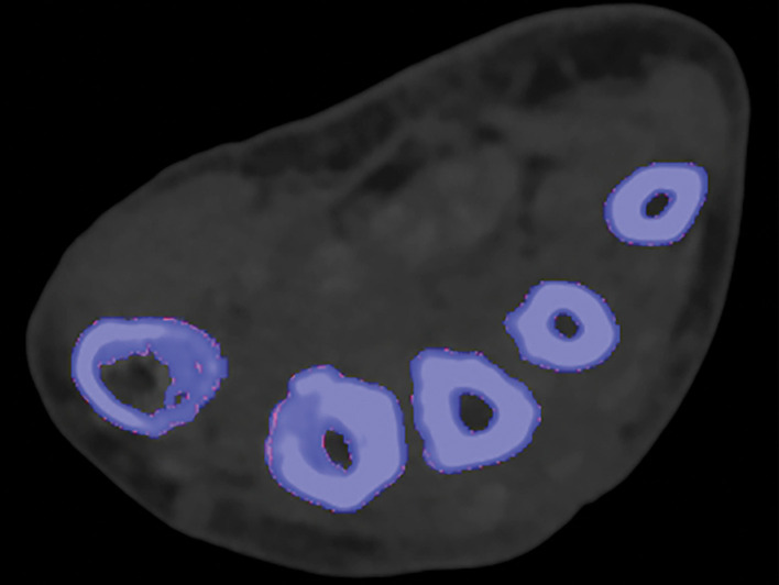
Constrained spectral FOV for small parts. Axial single-energy–equivalent image of the elbow obtained with a dual-source DECT scanner. Soft-tissue mineralization (arrow) associated with soft-tissue swelling (olecranon bursitis) (arrowhead) along the posterior aspect of the elbow lies outside the spectral FOV (dotted curved line). Therefore, material analysis for characterizing the mineralization as gouty deposits is not possible.
Figure 4b.
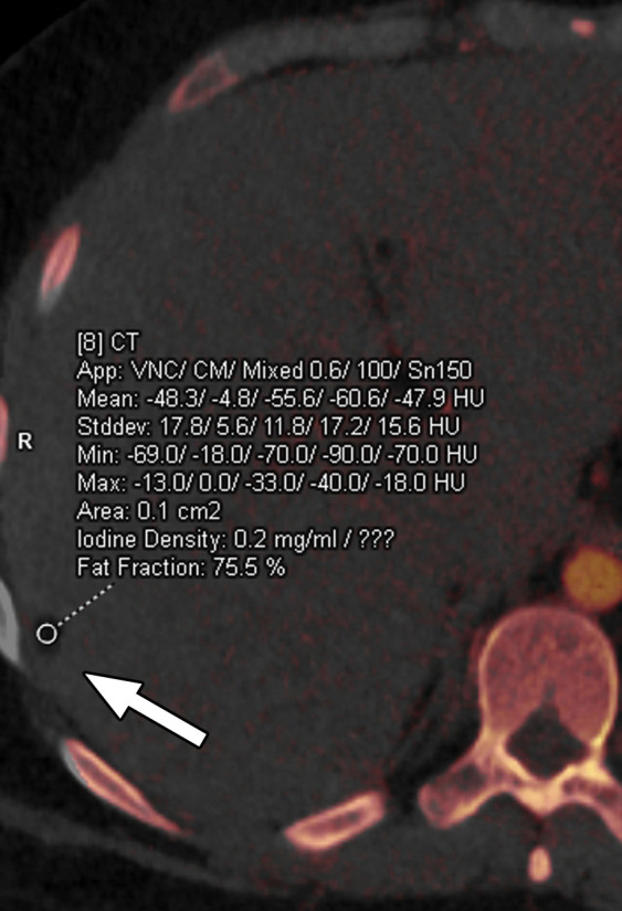
Constrained spectral FOV for the abdomen. Axial portovenous phase dual-source DECT images in a 20-year-old man with tuberous sclerosis. (a) Color overlay MD-fat image shows an 8-mm liver lesion (arrow) just within the limits of the spectral FOV. The limits of the FOV are sharply demarcated, and patient anatomy outside the field (arrowheads) is not color coded (ie, has no spectral information). (b) MD-iodine image shows no iodine uptake qualitatively or quantitatively (0.2 mg/mL) within the lesion (arrow), and quantitation confirms the presence of fat (75%), suggestive of angiomyolipoma. Material analysis of the lesion was possible because it lay within the spectral FOV.
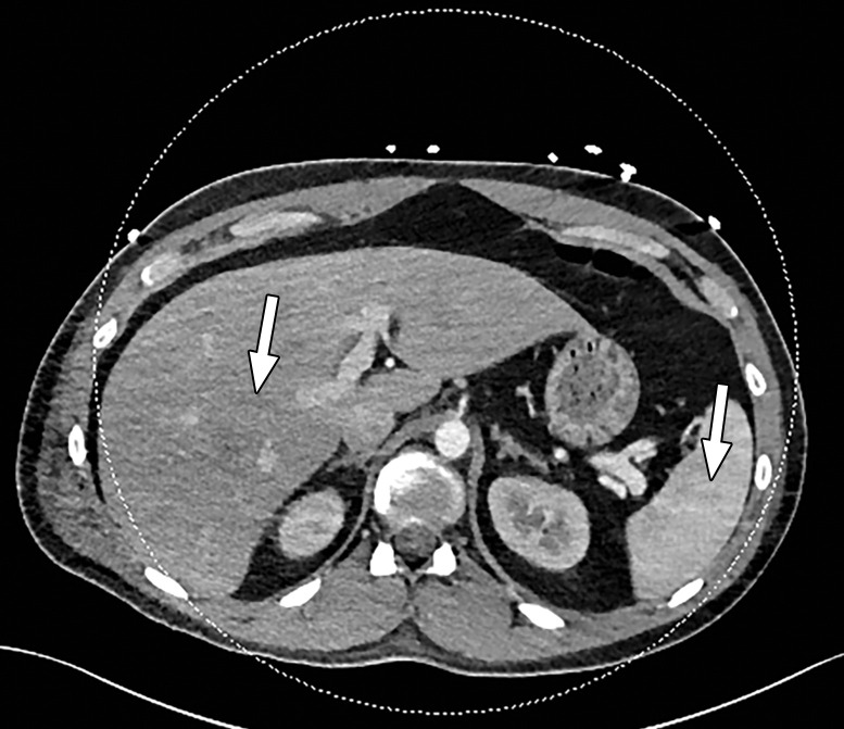
Abdominal acquisitions performed with the arms positioned along the side of the body result in beam-hardening artifacts at SECT (3). Beam-hardening artifacts from adjacent dense bony structures are seen as dark streaks or bands extending between or along the lines of two high-attenuating structures like bones owing to preferential attenuation of low-energy photons. Artifacts from the humerus placed along the side of the patient result in beam-hardening artifacts. These are seen on virtual monochromatic and MD reconstructions and can give an inaccurate representation of iodine distribution on an image (Fig 6).
Figure 6a.
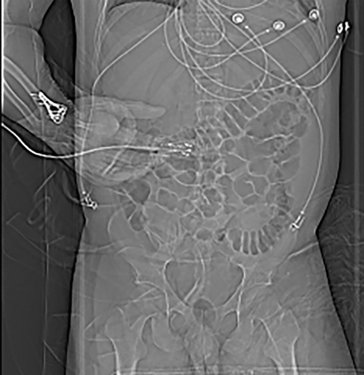
Beam hardening due to arm positioning. (a) Topographic image obtained for abdominopelvic CT with a dual-source scanner, which processes DECT images in the image domain, shows that the patient was scanned in the "right arm down" position. (b) Axial single-energy–equivalent image shows dark streaks (arrows) emanating from the humerus that extend across the liver and spleen. Dotted circle = spectral FOV. (c) On an axial color overlay MD-iodine image, the streaks (arrows) also affect depiction of iodine distribution. Even though the posterior hepatic segment (*) and spleen (arrowhead) lie within the spectral FOV (dotted circle), they artifactually show lack of iodine uptake, which can mimic a parenchymal infarct.
Figure 6b.
Beam hardening due to arm positioning. (a) Topographic image obtained for abdominopelvic CT with a dual-source scanner, which processes DECT images in the image domain, shows that the patient was scanned in the "right arm down" position. (b) Axial single-energy–equivalent image shows dark streaks (arrows) emanating from the humerus that extend across the liver and spleen. Dotted circle = spectral FOV. (c) On an axial color overlay MD-iodine image, the streaks (arrows) also affect depiction of iodine distribution. Even though the posterior hepatic segment (*) and spleen (arrowhead) lie within the spectral FOV (dotted circle), they artifactually show lack of iodine uptake, which can mimic a parenchymal infarct.
Figure 6c.
Beam hardening due to arm positioning. (a) Topographic image obtained for abdominopelvic CT with a dual-source scanner, which processes DECT images in the image domain, shows that the patient was scanned in the "right arm down" position. (b) Axial single-energy–equivalent image shows dark streaks (arrows) emanating from the humerus that extend across the liver and spleen. Dotted circle = spectral FOV. (c) On an axial color overlay MD-iodine image, the streaks (arrows) also affect depiction of iodine distribution. Even though the posterior hepatic segment (*) and spleen (arrowhead) lie within the spectral FOV (dotted circle), they artifactually show lack of iodine uptake, which can mimic a parenchymal infarct.
In theory, DECT techniques with image domain reconstruction are associated with more beam-hardening artifacts than DECT techniques with projection domain reconstruction. However, in practice beam-hardening artifacts are not completely eliminated on projection domain–reconstructed images owing to imperfect calibration (Fig 7) (29). Hence, it is imperative to raise the arms of the patient above the shoulder level to obtain good-quality images of the abdomen or lungs.
Figure 7a.
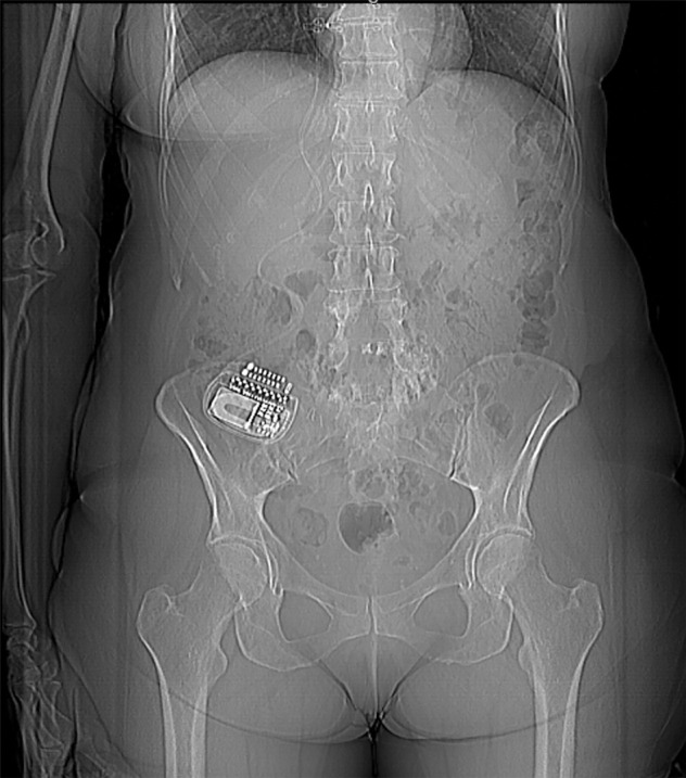
Beam hardening due to arm positioning. (a) Topographic image obtained for abdominopelvic CT with a dual-layer DECT scanner, which processes DECT images in the projection domain, shows that the patient was scanned in the "right arm down" position. (b, c) Axial conventional single-energy (b) and gray-scale MD-iodine (c) images show dark streaks (arrows) and bands (arrowhead) extending from the humerus, which degrade image quality and cause spurious lower attenuation and iodine distribution in the posterior hepatic segment (* in c).
Figure 7b.
Beam hardening due to arm positioning. (a) Topographic image obtained for abdominopelvic CT with a dual-layer DECT scanner, which processes DECT images in the projection domain, shows that the patient was scanned in the "right arm down" position. (b, c) Axial conventional single-energy (b) and gray-scale MD-iodine (c) images show dark streaks (arrows) and bands (arrowhead) extending from the humerus, which degrade image quality and cause spurious lower attenuation and iodine distribution in the posterior hepatic segment (* in c).
Figure 7c.
Beam hardening due to arm positioning. (a) Topographic image obtained for abdominopelvic CT with a dual-layer DECT scanner, which processes DECT images in the projection domain, shows that the patient was scanned in the "right arm down" position. (b, c) Axial conventional single-energy (b) and gray-scale MD-iodine (c) images show dark streaks (arrows) and bands (arrowhead) extending from the humerus, which degrade image quality and cause spurious lower attenuation and iodine distribution in the posterior hepatic segment (* in c).
Temporal Misregistration.—At SECT, the term temporal resolution refers to the ability to resolve highly mobile structures and is particularly relevant for cardiac imaging. It remains pertinent for DECT and is defined by the time taken to obtain spectral data from a given image voxel or section. Besides affecting image quality, as in SECT, it leads to a "spectral skew," since data for the two energies are offset from each other in time. Dual-spin and dual-source DECT are more susceptible to temporal misregistration and—by extension—to motion misregistration by virtue of the scanner design, and the misregistration cannot be mitigated by tweaking scan protocols.
Maximum temporal misregistration is observed in dual-spin DECT, especially when the entire scan volume is first acquired at one energy level, then the acquisition is repeated at another energy level. It not only affects moving structures such as the heart or if the patient moves between the two acquisitions but is also limited by changes in the degree of contrast medium opacification within vessels or parenchyma between the two acquisitions. The most obvious method of addressing this limitation is to reduce the time delay between acquisitions and alternate the energies at each gantry position instead of at the end of each scan volume. Another method of mitigating this is to obtain projection data for only a part of the gantry rotation (ie, a "partial acquisition").
The temporal skew in dual-source DECT is attributable to the orthogonally situated x-ray tubes. This tube design results in data—for any given section—being obtained at different projection angles for both energy levels. Therefore, it results in a delay of approximately one-fourth of the rotation time between the acquisitions at two energies for the same voxel. This offset differs between the three generations of the currently available commercial platform (Table 1). This temporal misregistration is the reason why material decomposition is performed in the image domain and not the projection domain in dual-source DECT. On the other hand, this same tube design is advantageous for improving temporal resolution and is leveraged for cardiac imaging when both tubes are operated at the same peak tube voltage in SECT mode.
Since the gold and tin filters are split along the z-axis in split-filter DECT, a spiral acquisition is necessary to ensure that both beams irradiate the same imaging volume for optimal spectral performance. Thus, pitch values are limited to less than 0.5 for DECT acquisitions with this platform, resulting in a temporal skew.
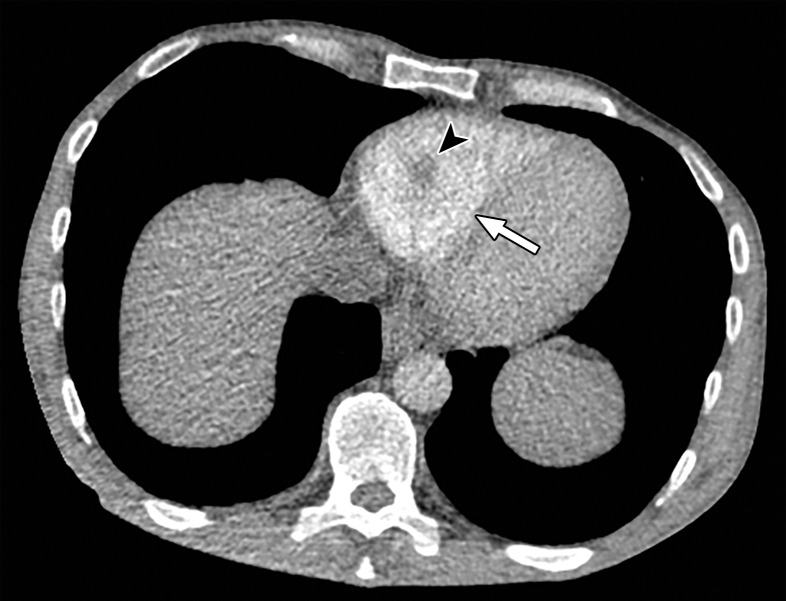
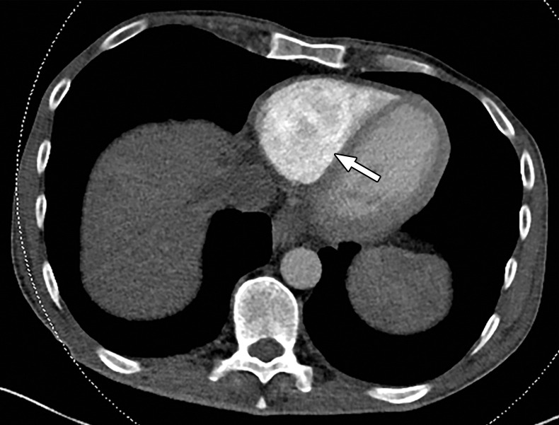
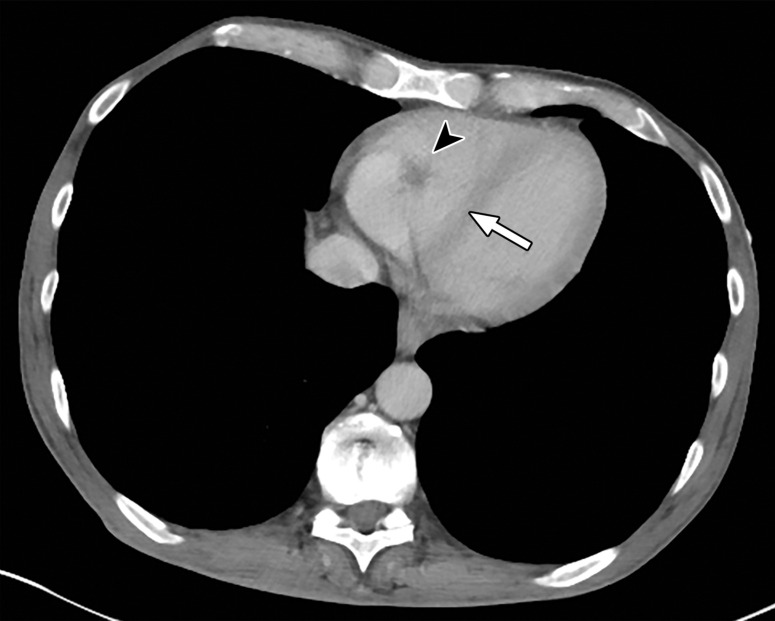
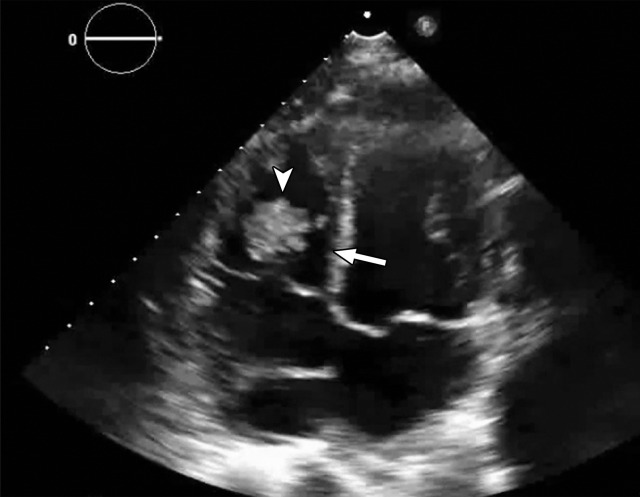
The temporal offset across all techniques is on the order of milliseconds and is most pertinent when imaging a noncompliant patient who moves between acquisitions or when structures are small (<3 mm) or excessively pulsatile (eg, cardia or aneurysmal sac) (Fig 8). Even so, misregistration with differences of up to 4.3 mm in the axial plane has been shown for relatively stationary structures like urinary stones and peripheral joints (30,31). These may be diminished by applying flexible registration techniques or increasing the speed of gantry rotation (32,33). Both rapid kVp switching DECT and dual-layer DECT have negligible temporal misregistration due to their inherent scanner design.
Figure 8a.
Temporal misregistration on images obtained with dual-source DECT. (a) Axial pulmonary CT angiogram from the 150-kVp Sn projection shows a subtle filling defect (arrowhead) in the right ventricle (arrow). (b) Axial single-energy–equivalent pulmonary CT angiogram, which contains projections from both voltages, shows no filling defect in the right ventricle (arrow). (c) Axial single-energy (120-kVp) abdominal CT image obtained on the same day clearly shows a filling defect (arrowhead) in the right ventricle (arrow). (d) Echocardiogram shows a thrombus (arrowhead) in the right ventricle (arrow). Nonvisualization of the thrombus at DECT was due to temporal offset between the two x-ray tubes.
Figure 8b.
Temporal misregistration on images obtained with dual-source DECT. (a) Axial pulmonary CT angiogram from the 150-kVp Sn projection shows a subtle filling defect (arrowhead) in the right ventricle (arrow). (b) Axial single-energy–equivalent pulmonary CT angiogram, which contains projections from both voltages, shows no filling defect in the right ventricle (arrow). (c) Axial single-energy (120-kVp) abdominal CT image obtained on the same day clearly shows a filling defect (arrowhead) in the right ventricle (arrow). (d) Echocardiogram shows a thrombus (arrowhead) in the right ventricle (arrow). Nonvisualization of the thrombus at DECT was due to temporal offset between the two x-ray tubes.
Figure 8c.
Temporal misregistration on images obtained with dual-source DECT. (a) Axial pulmonary CT angiogram from the 150-kVp Sn projection shows a subtle filling defect (arrowhead) in the right ventricle (arrow). (b) Axial single-energy–equivalent pulmonary CT angiogram, which contains projections from both voltages, shows no filling defect in the right ventricle (arrow). (c) Axial single-energy (120-kVp) abdominal CT image obtained on the same day clearly shows a filling defect (arrowhead) in the right ventricle (arrow). (d) Echocardiogram shows a thrombus (arrowhead) in the right ventricle (arrow). Nonvisualization of the thrombus at DECT was due to temporal offset between the two x-ray tubes.
Figure 8d.
Temporal misregistration on images obtained with dual-source DECT. (a) Axial pulmonary CT angiogram from the 150-kVp Sn projection shows a subtle filling defect (arrowhead) in the right ventricle (arrow). (b) Axial single-energy–equivalent pulmonary CT angiogram, which contains projections from both voltages, shows no filling defect in the right ventricle (arrow). (c) Axial single-energy (120-kVp) abdominal CT image obtained on the same day clearly shows a filling defect (arrowhead) in the right ventricle (arrow). (d) Echocardiogram shows a thrombus (arrowhead) in the right ventricle (arrow). Nonvisualization of the thrombus at DECT was due to temporal offset between the two x-ray tubes.
Special Considerations.—Split-filter DECT and photon-counting DECT have unique limitations that are not observed with SECT or other DECT platforms. Since a commercial scanner using the photon-counting technique is not yet available, this remains beyond the scope of this article.
Distinct to split-filter DECT, the central 2–3-mm portion of the filtered beam contains a mixture of gold and tin spectra due to constraints in focal spot size. Similarly, a mixed spectrum is seen at the edges of the detector owing to penumbra effects. Therefore, approximately 3-cm fringes on both ends of the acquisition cannot be optimally interrogated for spectral information. Both the edges and central portions can thus be used to reconstruct SECT-equivalent images reliably, but not for DECT evaluations.
DECT Image Postprocessing
After acquisition, choosing the right parameters (eg, kernel, decomposition ratio) is essential during postprocessing to avoid qualitative and quantitative interpretive errors.
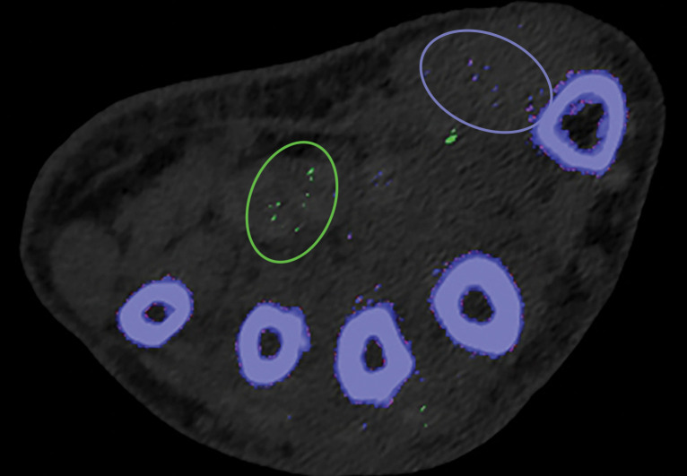
Kernel Selection.—Poisson image noise occurs owing to statistical errors of low photon counts. On MD images, it can be seen as submillimeter foci of colored pixels and erroneously interpreted as enhancement or gouty deposition (green pixels by default in dual-source DECT) on MD-iodine and MD-urate images, respectively. On dual-source DECT–derived gout image reconstructions, appropriate kernel selection that smoothens images (D kernel; filtered back projection) or reduces beam hardening (Q kernel; iterative reconstruction) has been suggested to mitigate such artifacts (Fig 9) (33). Also, images should be postprocessed only with source data.
Figure 9a.
Appropriate kernel selection. MD-urate images of the wrist for gout evaluation with dual-source DECT. (a) Image processed with a bone kernel (Qr59d) shows artifactual green and blue pixels in the soft tissue that would indicate urate and calcium deposits, respectively (colors by default from the vendor). (b) On an image processed correctly with a soft-tissue kernel (Bf32d), these colored pixels have been removed and shown to be artifactual.
Figure 9b.
Appropriate kernel selection. MD-urate images of the wrist for gout evaluation with dual-source DECT. (a) Image processed with a bone kernel (Qr59d) shows artifactual green and blue pixels in the soft tissue that would indicate urate and calcium deposits, respectively (colors by default from the vendor). (b) On an image processed correctly with a soft-tissue kernel (Bf32d), these colored pixels have been removed and shown to be artifactual.
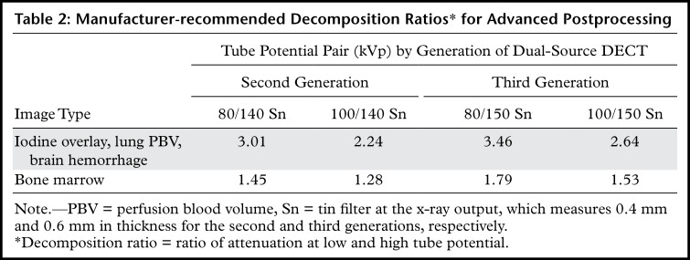
Appropriate Decomposition Ratio Selection.—The ability to discriminate materials relies on the differences in their effective atomic number and attenuation profile with at least two different energies. At dual-source DECT, the latter, a decomposition ratio (DER) (ratio of attenuation at low and high kVp), is clinically used in postprocessing DECT images. It is influenced by spectral separation and thus varies not only on the basis of the kVp pair used for acquisition (80/140 kVp Sn vs 100/140 kVp Sn) but also between the three generations of dual-source DECT owing to different available x-ray spectra of the high-kVp tube (140 kVp vs 140 kVp Sn vs 150 kVp Sn).
The higher the spectral separation, the higher the DER and the lower the image noise on VNC and virtual noncalcium images (34,35). Although manufacturer-recommended DERs have been provided (Table 2), investigators typically make empirical changes based on their experience (36–38). Systematic investigations are necessary for standardizing the ratios for different voltage pairs and clinical tasks.
Table 2:
Manufacturer-recommended Decomposition Ratios* for Advanced Postprocessing
Thresholding Parameter Selection.—When estimating tophus burden with dual-source DECT, Strobl et al (39) found that when all other parameters such as edge enhancement (range), DER, and air and bone distances (distance between suspected urate voxel and air or bone, respectively) were kept constant, a modified attenuation threshold of 120 HU correlated better with US results compared with the vendor-recommended threshold of 150 HU (Fig 10). These findings are unique to the tube potentials (80/140 kVp Sn) used by the authors, and more work is needed to ascertain appropriate thresholds for different kVp pairs. Importantly, a lower threshold is more susceptible to artifacts, which may lead to an increase in the number of false positives and overestimation of gout volume on volume-rendered images, requiring reader expertise and manual removal from the volume-rendered images.
Figure 10a.
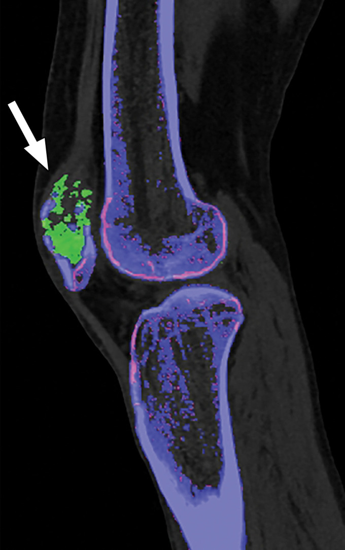
Appropriate selection of postprocessing attenuation threshold. Sagittal color overlay MD-urate images obtained with dual-source DECT for gout evaluation show monosodium urate deposition (green) in the soft tissue associated with the lytic lesion involving the patella (arrow). Image processed using 120 HU as the minimum attenuation threshold (a) shows a larger (6.77 cm3) and more accurate representation of the tophus deposit compared with the image processed using 150 HU as the threshold (b) (3.39 cm3).
Figure 10b.
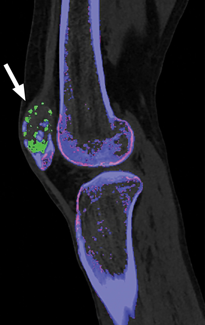
Appropriate selection of postprocessing attenuation threshold. Sagittal color overlay MD-urate images obtained with dual-source DECT for gout evaluation show monosodium urate deposition (green) in the soft tissue associated with the lytic lesion involving the patella (arrow). Image processed using 120 HU as the minimum attenuation threshold (a) shows a larger (6.77 cm3) and more accurate representation of the tophus deposit compared with the image processed using 150 HU as the threshold (b) (3.39 cm3).
At dual-layer DECT, use of an appropriate calcium suppression index (range of 25–100, with a default setting of 76) is required for processing virtual noncalcium images. Lower indexes suppress tissues with low calcium composition weight, such as trabecular or spongy bone. Higher indexes suppress tissues with high calcium composition weight, such as cortical bone. Increasing the calcium suppression index increases the contrast-to-noise ratio for detecting bone marrow edema (40).
DECT Image Display
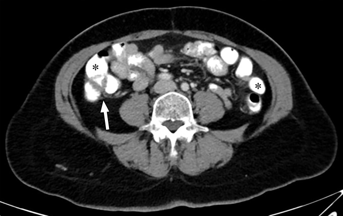
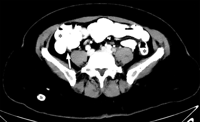
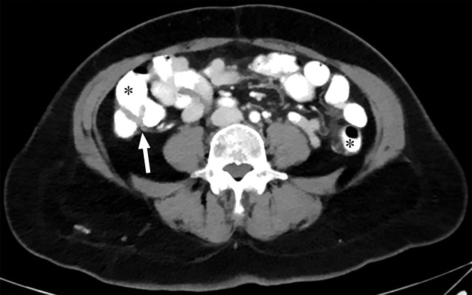
If the window widths (WWs) and window levels (WLs) that are used for conventional polychromatic 120-kVp SECT images are used to view low-keV images, it would result in blooming of structures that take up or are filled with iodine or barium. Wider window settings are needed for optimal display of low-keV images (Fig 11) (41). These window values can be approximately twofold higher for these images than for 120-kVp SECT images across all DECT techniques (41–43).
Figure 11a.
Optimization of window settings for virtual monochromatic (VMC) images. Axial portovenous phase abdominopelvic CT images obtained with iodinated oral contrast medium (*) show the bowel wall and folds (arrow). (a) A 120-kVp image at window width (WW) of 360 HU and window level (WL) of 60 HU. (b) A 40-keV VMC image at the same window settings shows significant "blooming" of contrast medium, hindering visualization of the bowel wall and folds. (c) A 40-keV VMC image at wider window settings (WW = 589 HU, WL = 88 HU) provides optimal display.
Figure 11b.
Optimization of window settings for virtual monochromatic (VMC) images. Axial portovenous phase abdominopelvic CT images obtained with iodinated oral contrast medium (*) show the bowel wall and folds (arrow). (a) A 120-kVp image at window width (WW) of 360 HU and window level (WL) of 60 HU. (b) A 40-keV VMC image at the same window settings shows significant "blooming" of contrast medium, hindering visualization of the bowel wall and folds. (c) A 40-keV VMC image at wider window settings (WW = 589 HU, WL = 88 HU) provides optimal display.
Figure 11c.
Optimization of window settings for virtual monochromatic (VMC) images. Axial portovenous phase abdominopelvic CT images obtained with iodinated oral contrast medium (*) show the bowel wall and folds (arrow). (a) A 120-kVp image at window width (WW) of 360 HU and window level (WL) of 60 HU. (b) A 40-keV VMC image at the same window settings shows significant "blooming" of contrast medium, hindering visualization of the bowel wall and folds. (c) A 40-keV VMC image at wider window settings (WW = 589 HU, WL = 88 HU) provides optimal display.
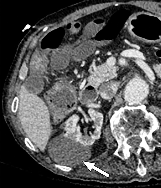
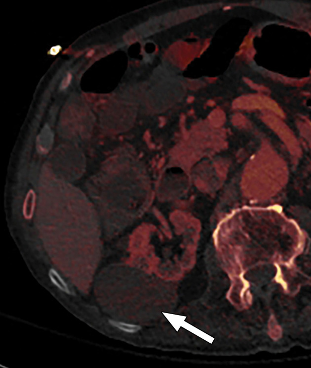
Appropriate WWs and WLs are also important for accurate interpretation of MD-iodine images. If the window settings are incorrect, iodine is seen in structures like air or subcutaneous fat that definitely do not contain iodine. The window settings for MD-iodine images should be adjusted by using internal controls like fat, air, or unopacified bladder as a guide to avoid a false impression of enhancement (Fig 12) (44).
Figure 12a.
Optimization of window settings for MD-iodine images. (a) Axial single-energy–equivalent image shows a simple fluid-attenuation cyst in the right kidney (arrow). (b) Axial color overlay MD-iodine image shows spurious uptake of iodine (dark red) by the cyst (arrow) due to improper window settings. Also note the false presence of iodine in the gallbladder (*), subcutaneous fat (arrowhead), and air. (c) Axial color overlay MD-iodine image with appropriate window display shows lack of iodine in the cyst (arrow).
Figure 12b.
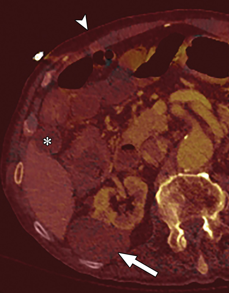
Optimization of window settings for MD-iodine images. (a) Axial single-energy–equivalent image shows a simple fluid-attenuation cyst in the right kidney (arrow). (b) Axial color overlay MD-iodine image shows spurious uptake of iodine (dark red) by the cyst (arrow) due to improper window settings. Also note the false presence of iodine in the gallbladder (*), subcutaneous fat (arrowhead), and air. (c) Axial color overlay MD-iodine image with appropriate window display shows lack of iodine in the cyst (arrow).
Figure 12c.
Optimization of window settings for MD-iodine images. (a) Axial single-energy–equivalent image shows a simple fluid-attenuation cyst in the right kidney (arrow). (b) Axial color overlay MD-iodine image shows spurious uptake of iodine (dark red) by the cyst (arrow) due to improper window settings. Also note the false presence of iodine in the gallbladder (*), subcutaneous fat (arrowhead), and air. (c) Axial color overlay MD-iodine image with appropriate window display shows lack of iodine in the cyst (arrow).
For institutions with a multivendor setup, it is important to note that WWs and WLs for the same keV level and MD-iodine image reconstruction may vary among the different platforms (Fig 13). At our institution, we use WW/WL settings of 150/50 HU, 250/127 HU, and 7/3 HU for MD-iodine images acquired with rapid kVp switching DECT, dual-source DECT, and dual-layer DECT, respectively. Appropriate setting of WW and WL at the time of relay from the scanner to the picture archiving and communication system (PACS) would lead to improved workflow for radiologists.
Figure 13a.
Window settings for MD-iodine images. Images obtained with different DECT platforms require different window width (WW) and window level (WL) settings. At our institution, we view MD-iodine images from dual-layer DECT at WW = 7 HU and WL = 3 HU (a), those from rapid kVp switching DECT at WW = 150 HU and WL = 50 HU (b), and those from dual-source DECT at WW = 250 HU and WL = 127 HU (c).
Figure 13b.
Window settings for MD-iodine images. Images obtained with different DECT platforms require different window width (WW) and window level (WL) settings. At our institution, we view MD-iodine images from dual-layer DECT at WW = 7 HU and WL = 3 HU (a), those from rapid kVp switching DECT at WW = 150 HU and WL = 50 HU (b), and those from dual-source DECT at WW = 250 HU and WL = 127 HU (c).
Figure 13c.
Window settings for MD-iodine images. Images obtained with different DECT platforms require different window width (WW) and window level (WL) settings. At our institution, we view MD-iodine images from dual-layer DECT at WW = 7 HU and WL = 3 HU (a), those from rapid kVp switching DECT at WW = 150 HU and WL = 50 HU (b), and those from dual-source DECT at WW = 250 HU and WL = 127 HU (c).
Conclusion
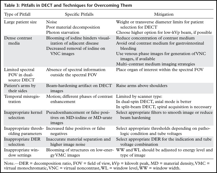
DECT is an exciting innovation in CT technology, with tremendous capabilities for improving diagnosis and adding value to patient care in routine clinical practice. Although substantial advances in this technology have occurred in the past decade, there have also been challenges in its routine implementation due to the workflow considerations, large number of different image data sets, and complex physical principles involved in material decomposition. Inherent in this technology are certain artifacts that need to be recognized to realize the full value of DECT and avoid diagnostic errors. An overview of the pitfalls and strategies for mitigation is presented in Table 3.
Table 3:
Pitfalls in DECT and Techniques for Overcoming Them
Continuing research efforts and vendor collaborations are critical to address some of these challenges. It is important to remember that the artifacts and technical limitations described in this article are a snapshot in time, as this technology continues to evolve.
Acknowledgments
Acknowledgments
The authors would like to thank Francis Deng, MD, for sharing DECT cases in intradepartmental conferences and Cristy Savage, RTR, for continued discussions pertaining to DECT workflow.
S.L. supported in part by Deutsche Forschungsgemeinschaft LE 4401/1-1 (project 426969820).
B.M.Y. supported by grants 5R01CA226868-02 and 5R42DK104580-04 from the National Institutes of Health.
Recipient of a Certificate of Merit award for an education exhibit at the 2019 RSNA Annual Meeting.
For this journal-based SA-CME activity, the authors C.A., S.L., P.R., B.M.Y., and A.R.K. have provided disclosures; all other authors, the editor, and the reviewers have disclosed no relevant relationships.
Disclosures of Conflicts of Interest.—: C.A. Activities related to the present article: grant from Philips Healthcare. Activities not related to the present article: disclosed no relevant relationships. Other activities: disclosed no relevant relationships. S.L. Activities related to the present article: disclosed no relevant relationships. Activities not related to the present article: grant from Koninklijke Philips NV. Other activities: disclosed no relevant relationships. P.R. Activities related to the present article: disclosed no relevant relationships. Activities not related to the present article: royalties from Elsevier. Other activities: disclosed no relevant relationships. B.M.Y. Activities related to the present article: grants from Philips Healthcare and GE Healthcare. Activities not related to the present article: board member for Nextrast; consultant for GE Healthcare; expert testimony for the Markam Group; grant from Guerbet; speaker for Philips Healthcare and GE Healthcare; royalties from Oxford University Press; shareholder in Nextrast; travel reimbursement from Nextrast. Other activities: patents pending on potential CT contrast agents; royalties from licensed patents. A.R.K. Activities related to the present article: grant from Philips Healthcare. Activities not related to the present article: disclosed no relevant relationships. Other activities: disclosed no relevant relationships.
Abbreviations:
- DECT
- dual-energy CT
- FOV
- field of view
- keV
- kilo–electron volt
- kVp
- kilovolt peak
- MD
- material density
- SECT
- single-energy CT
- Sn
- tin filter
- VNC
- virtual noncontrast
References
- 1.Itani M, Bresnahan BW, Rice K, et al. Clinical and Payer-Based Analysis of Value of Dual-Energy Computed Tomography for Workup of Incidental Abdominal Findings. J Comput Assist Tomogr 2019;43(4):605–611. [DOI] [PubMed] [Google Scholar]
- 2.Atwi NE, Sabottke CF, Pitre DM, et al. Follow-up Recommendation Rates Associated With Spectral Detector Dual-Energy CT of the Abdomen and Pelvis: A Retrospective Comparison to Single-Energy CT. J Am Coll Radiol 2020;17(7):940–950. [DOI] [PubMed] [Google Scholar]
- 3.Barrett JF, Keat N. Artifacts in CT: recognition and avoidance. RadioGraphics 2004;24(6):1679–1691. [DOI] [PubMed] [Google Scholar]
- 4.Long Z, DeLone DR, Kotsenas AL, et al. Clinical Assessment of Metal Artifact Reduction Methods in Dual-Energy CT Examinations of Instrumented Spines. AJR Am J Roentgenol 2019;212(2):395–401. [DOI] [PubMed] [Google Scholar]
- 5.Neogi T, Jansen TL, Dalbeth N, et al. 2015 Gout Classification Criteria: an American College of Rheumatology/European League against Rheumatism collaborative initiative. Arthritis Rheumatol 2015;67(10):2557–2568. [Published correction appears in Arthritis Rheumatol 2016;68(2):515.] [DOI] [PMC free article] [PubMed] [Google Scholar]
- 6.McCollough CH, Leng S, Yu L, Fletcher JG. Dual- and Multi-Energy CT: Principles, Technical Approaches, and Clinical Applications. Radiology 2015;276(3):637–653. [DOI] [PMC free article] [PubMed] [Google Scholar]
- 7.Patel BN, Alexander L, Allen B, et al. Dual-energy CT workflow: multi-institutional consensus on standardization of abdominopelvic MDCT protocols. Abdom Radiol (NY) 2017;42(3):676–687. [DOI] [PubMed] [Google Scholar]
- 8.Baliyan V, Kordbacheh H, Pourvaziri A, et al. Rapid kVp-switching DECT portal venous phase abdominal CT scans in patients with large body habitus: image quality considerations. Abdom Radiol (NY) 2020;45(9):2902–2909. [DOI] [PubMed] [Google Scholar]
- 9.Guimarães LS, Fletcher JG, Harmsen WS, et al. Appropriate patient selection at abdominal dual-energy CT using 80 kV: relationship between patient size, image noise, and image quality. Radiology 2010;257(3):732–742. [DOI] [PubMed] [Google Scholar]
- 10.Jepperson MA, Cernigliaro JG, Sella D, et al. Dual-energy CT for the evaluation of urinary calculi: image interpretation, pitfalls and stone mimics. Clin Radiol 2013;68(12):e707–e714. [DOI] [PubMed] [Google Scholar]
- 11.Lambert JW, FitzGerald PF, Edic PM, et al. The Effect of Patient Diameter on the Dual-Energy Ratio of Selected Contrast-Producing Elements. J Comput Assist Tomogr 2017;41(3):505–510. [DOI] [PMC free article] [PubMed] [Google Scholar]
- 12.Kordbacheh H, Baliyan V, Singh P, Eisner BH, Sahani DV, Kambadakone AR. Rapid kVp switching dual-energy CT in the assessment of urolithiasis in patients with large body habitus: preliminary observations on image quality and stone characterization. Abdom Radiol (NY) 2019;44(3):1019–1026. [DOI] [PubMed] [Google Scholar]
- 13.Kordbacheh H, Baliyan V, Uppot RN, Eisner BH, Sahani DV, Kambadakone AR. Dual-Source Dual-Energy CT in Detection and Characterization of Urinary Stones in Patients With Large Body Habitus: Observations in a Large Cohort. AJR Am J Roentgenol 2019;212(4):796–801. [DOI] [PubMed] [Google Scholar]
- 14.Ehn S, Sellerer T, Muenzel D, et al. Assessment of quantification accuracy and image quality of a full-body dual-layer spectral CT system. J Appl Clin Med Phys 2018;19(1):204–217. [DOI] [PMC free article] [PubMed] [Google Scholar]
- 15.Gauntt DM. A suggested method for setting up GSI profiles on the GE Revolution CT scanner. J Appl Clin Med Phys 2019;20(12):169–179. [DOI] [PMC free article] [PubMed] [Google Scholar]
- 16.Fursevich DM, LiMarzi GM, O’Dell MC, Hernandez MA, Sensakovic WF. Bariatric CT Imaging: Challenges and Solutions. RadioGraphics 2016;36(4):1076–1086. [DOI] [PubMed] [Google Scholar]
- 17.Baliyan V, Kordbacheh H, Serrao J, Sahani DV, Kambadakone AR. Dual-Source Dual-Energy CT Portal Venous Phase Abdominal CT Scans in Large Body Habitus Patients: Preliminary Observations on Image Quality and Material Decomposition. J Comput Assist Tomogr 2018;42(6):932–936. [DOI] [PubMed] [Google Scholar]
- 18.Atwi NE, Smith DL, Flores CD, et al. Dual-energy CT in the obese: a preliminary retrospective review to evaluate quality and feasibility of the single-source dual-detector implementation. Abdom Radiol (NY) 2019;44(2):783–789. [DOI] [PubMed] [Google Scholar]
- 19.Lu X, Lu Z, Yin J, Gao Y, Chen X, Guo Q. Effects of radiation dose levels and spectral iterative reconstruction levels on the accuracy of iodine quantification and virtual monochromatic CT numbers in dual-layer spectral detector CT: an iodine phantom study. Quant Imaging Med Surg 2019;9(2):188–200. [DOI] [PMC free article] [PubMed] [Google Scholar]
- 20.van Ommen F, Bennink E, Vlassenbroek A, et al. Image quality of conventional images of dual-layer spectral CT: a phantom study. Med Phys 2018;45(7):3031–3042. [DOI] [PubMed] [Google Scholar]
- 21.Sauter AP, Kopp FK, Münzel D, et al. Accuracy of iodine quantification in dual-layer spectral CT: influence of iterative reconstruction, patient habitus and tube parameters. Eur J Radiol 2018;102:83–88. [DOI] [PubMed] [Google Scholar]
- 22.Parakh A, Macri F, Sahani D. Dual-Energy Computed Tomography: Dose Reduction, Series Reduction, and Contrast Load Reduction in Dual-Energy Computed Tomography. Radiol Clin North Am 2018;56(4):601–624. [DOI] [PubMed] [Google Scholar]
- 23.Parakh A, Negreros-Osuna AA, Patino M, McNulty F, Kambadakone A, Sahani DV. Low-keV and Low-kVp CT for Positive Oral Contrast Media in Patients with Cancer: A Randomized Clinical Trial. Radiology 2019;291(3):620–629. [DOI] [PubMed] [Google Scholar]
- 24.Patino M, Parakh A, Lo GC, et al. Virtual Monochromatic Dual-Energy Aortoiliac CT Angiography With Reduced Iodine Dose: A Prospective Randomized Study. AJR Am J Roentgenol 2019;212(2):467–474. [DOI] [PubMed] [Google Scholar]
- 25.Yeh BM, Obmann MM, Westphalen AC, et al. Dual Energy Computed Tomography Scans of the Bowel: Benefits, Pitfalls, and Future Directions. Radiol Clin North Am 2018;56(5):805–819. [DOI] [PubMed] [Google Scholar]
- 26.Muenzel D, Daerr H, Proksa R, et al. Simultaneous dual-contrast multi-phase liver imaging using spectral photon-counting computed tomography: a proof-of-concept study. Eur Radiol Exp 2017;1(1):25. [DOI] [PMC free article] [PubMed] [Google Scholar]
- 27.Yeh BM, FitzGerald PF, Edic PM, et al. Opportunities for new CT contrast agents to maximize the diagnostic potential of emerging spectral CT technologies. Adv Drug Deliv Rev 2017;113:201–222. [DOI] [PMC free article] [PubMed] [Google Scholar]
- 28.Lee JA, Jeong WK, Kim Y, et al. Dual-energy CT to detect recurrent HCC after TACE: initial experience of color-coded iodine CT imaging. Eur J Radiol 2013;82(4):569–576. [DOI] [PubMed] [Google Scholar]
- 29.Goodsitt MM, Christodoulou EG, Larson SC. Accuracies of the synthesized monochromatic CT numbers and effective atomic numbers obtained with a rapid kVp switching dual energy CT scanner. Med Phys 2011;38(4): 2222–2232. [DOI] [PubMed] [Google Scholar]
- 30.Eiber M, Holzapfel K, Frimberger M, et al. Targeted dual-energy single-source CT for characterisation of urinary calculi: experimental and clinical experience. Eur Radiol 2012;22(1):251–258. [DOI] [PubMed] [Google Scholar]
- 31.Diekhoff T, Ziegeler K, Feist E, et al. First experience with single-source dual-energy computed tomography in six patients with acute arthralgia: a feasibility experiment using joint aspiration as a reference. Skeletal Radiol 2015;44(11):1573–1577. [DOI] [PubMed] [Google Scholar]
- 32.Leng S, Shiung M, Ai S, et al. Feasibility of discriminating uric acid from non–uric acid renal stones using consecutive spatially registered low- and high-energy scans obtained on a conventional CT scanner. AJR Am J Roentgenol 2015;204(1):92–97. [DOI] [PMC free article] [PubMed] [Google Scholar]
- 33.Mallinson PI, Coupal T, Reisinger C, et al. Artifacts in dual-energy CT gout protocol: a review of 50 suspected cases with an artifact identification guide. AJR Am J Roentgenol 2014;203(1):W103–W109. [DOI] [PubMed] [Google Scholar]
- 34.Krauss B, Grant KL, Schmidt BT, Flohr TG. The importance of spectral separation: an assessment of dual-energy spectral separation for quantitative ability and dose efficiency. Invest Radiol 2015;50(2):114–118. [DOI] [PubMed] [Google Scholar]
- 35.Müller FC, Børgesen H, Gosvig K, et al. Optimising dual-energy CT scan parameters for virtual non-calcium imaging of the bone marrow: a phantom study. Eur Radiol Exp 2019;3(1):46. [DOI] [PMC free article] [PubMed] [Google Scholar]
- 36.Wu H, Zhang G, Shi L, et al. Axial Spondyloarthritis: Dual-Energy Virtual Noncalcium CT in the Detection of Bone Marrow Edema in the Sacroiliac Joints. Radiology 2019;290(1):157–164. [DOI] [PubMed] [Google Scholar]
- 37.Wang CK, Tsai JM, Chuang MT, Wang MT, Huang KY, Lin RM. Bone marrow edema in vertebral compression fractures: detection with dual-energy CT. Radiology 2013;269(2):525–533. [DOI] [PubMed] [Google Scholar]
- 38.Pache G, Krauss B, Strohm P, et al. Dual-energy CT virtual noncalcium technique: detecting posttraumatic bone marrow lesions—feasibility study. Radiology 2010;256(2):617–624. [DOI] [PubMed] [Google Scholar]
- 39.Strobl S, Kremser C, Taljanovic M, et al. Impact of Dual-Energy CT Postprocessing Protocol for the Detection of Gouty Arthritis and Quantification of Tophi in Patients Presenting With Podagra: Comparison With Ultrasound. AJR Am J Roentgenol 2019;213(6):1315–1323. [DOI] [PubMed] [Google Scholar]
- 40.Neuhaus V, Lennartz S, Abdullayev N, et al. Bone marrow edema in traumatic vertebral compression fractures: diagnostic accuracy of dual-layer detector CT using calcium suppressed images. Eur J Radiol 2018;105:216–220. [DOI] [PubMed] [Google Scholar]
- 41.Noda Y, Goshima S, Kozaka K, et al. Optimal window settings in single-source dual-energy computed tomography of the abdomen. Eur J Radiol 2018;109:204–209. [DOI] [PubMed] [Google Scholar]
- 42.Hickethier T, Iuga AI, Lennartz S, et al. Virtual Monoenergetic Images From a Novel Dual-Layer Spectral Detector Computed Tomography Scanner in Portal Venous Phase: Adjusted Window Settings Depending on Assessment Focus Are Essential for Image Interpretation. J Comput Assist Tomogr 2018;42(3):350–356. [DOI] [PubMed] [Google Scholar]
- 43.De Cecco CN, Caruso D, Schoepf UJ, et al. Optimization of window settings for virtual monoenergetic imaging in dual-energy CT of the liver: a multi-reader evaluation of standard monoenergetic and advanced imaged-based monoenergetic datasets. Eur J Radiol 2016;85(4):695–699. [DOI] [PubMed] [Google Scholar]
- 44.Wortman JR, Sodickson AD. Pearls, Pitfalls, and Problems in Dual-Energy Computed Tomography Imaging of the Body. Radiol Clin North Am 2018;56(4):625–640. [DOI] [PubMed] [Google Scholar]


