

Abstract
Treating vascular grafts failure requires complex surgery procedures and is associated with high risks. A real-time monitoring vascular system enables quick and reliable identification of complications and initiates safer treatments early. Here, an electric fieldassisted 3D printing technology is developed to fabricate in situ-poled ferroelectric artificial arteries that offer battery-free real-time blood pressure sensing and occlusion monitoring capability. The functional artery architecture is made possible by the development of a ferroelectric biocomposite which can be quickly polarized during printing and reshaped into devised objects. The synergistic effect from the potassium sodium niobite particles and the polyvinylidene fluoride polymer matrix yields a superb piezoelectric performance (bulk-scale d33 > 12 pC N−1). The sinusoidal architecture brings the mechanical modulus close to the level of blood vessels. The desired piezoelectric and mechanical properties of the artificial artery provide an excellent sensitivity to pressure change (0.306 mV mmHg−1, R2 > 0.99) within the range of human blood pressure (11.25–225.00 mmHg). The high pressure sensitivity and the ability to detect subtle vessel motion pattern change enable early detection of partial occlusion (e.g., thrombosis), allowing for preventing grafts failure. This work demonstrates a promising strategy of incorporating multifunctionality to artificial biological systems for smart healthcare systems.
Keywords: 3D printing, artificial artery, ferroelectric, functional implants, self-powered monitoring
1. Introduction
Vascular replacement is a common surgical procedure for repairing clot-obstructed or nonfunctional blood vessels in the treatment of coronary disease, stroke, and limb-threatening ischemia.[1] According to recent studies, about 450 000 prosthetic vascular grafts implantations have been conducted annually in the United States.[2] Comparing to conventional casting, molding, or electrospinning technology,[3] 3D printing technology offers a promising avenue toward rapidly creating complex biomimetic vascular grafts with heterogeneous properties close to those of native tissues and precise matching of anatomy of the individual, allowing patient-specific implants.[4] However, failure in the vascular implants could still occur without significant premonitory symptoms. Particularly 40–60% vascular grafts fail within the first year of implantation, which results in morbidity and even mortality.[5] It is essential to closely and timely monitor the associated local physiological signals (e.g., blood flow pressure, graft flow velocity, and variation in lumen dimensions) in order to detect hemodynamically significant lesions at early stage. Currently, implanted blood vessels require series of surveillances at defined time intervals in clinics using sophisticated equipment (such as ultrasound imaging devices, blood cuff, and contrast enhanced computerized tomography (CT)), which are still inadequate and ineffective to timely detect complications and prevent failure.[6] Treating grafts failure (e.g., occlusion) often requires complex surgery procedures associating with a high mortality rate of up to 5%, and only 25% of failed grafts could be effectively salvaged.[7] Real-time monitoring of implanted vascular grafts is thus greatly desired to reliably identify complications and initiate early treatment, which could be performed through a safer and less invasive procedure (e.g., local angioplasty through an endovascular procedure[8]). Self-powering capability is of great importance for future smart implants[9] and embodiment of battery-free sensing capability to related physiological signal (e.g., pressure) inside artificial vessels can be an ideal solution to realizing real-time monitoring function and minimizing the risk of implants failure.[7b,10]
Ferroelectric materials are an ideal selection for precision pressure and motion sensing owing to their outstanding piezoelectric responses. They have also been broadly used as a key functional component for nanogenerators that are considered as a promising strategy for achieving self-powered implantable electronics by harvesting energy locally from body motions.[11] Current piezoelectric implants are all devised with simple geometry (mostly film and disk) as organs/tissue attachments. Therefore, they often associated with issues of detachment, low sensitivity, and could bring an extra burden to the attached organ/tissue. It is ideal to have the functionality being a built-in feature of artificial organs/tissues. Recent advances in additive manufacturing opened up the possibility of creating complex geometry of biological implants. Nevertheless, only a few attempts have been demonstrated so far to fabricate ferroelectric structure using 3D printing with fair electromechanical coupling properties after long-time postpoling.[12] The structures that can be feasibly printed are extremely limited due to the requirement of high and uniform electric field for poling. However, compositional and structural inhomogeneity usually becomes more serious in larger complex prints, which could easily lead to breakdown (poling failure). In general, current 3D printing technology for ferroelectric structures is rather far from creating practical biological components. Here, we report an electric field-assisted 3D printing technology that allows for fast printing of complex and spontaneously polarized ferroelectric structures with high fidelity and superb piezoelectric performance. The prints consisted of ferroelectric potassium sodium niobate (KNN) particles embedded within a ferroelectric polyvinylidene fluoride (PVDF) polymer matrix, which can be poled during printing within a few seconds. The as- fabricated ferroelectric structure exhibited an impressive bulk-scale piezoelectric d33 over 12 pC N−1 and excellent force/pressure sensitivity. Using this technology, a smart artificial artery was directly printed, which was able to provide real-time precise sensing of blood pressure and vessel motion pattern, enabling early detection of partial occlusion.
2. Results and Discussions
2.1. Electric Field-Assisted 3D-Printing
A fuse deposition modeling (FDM) technology was used to melt the printing material and reshape it with the assistance of an electric field (Figure 1a). A ferroelectric composite consisting of 35 vol% functionalized sodium potassium niobate (KNN) piezoceramic particles (prepared by solid state reaction, Figure S1, Supporting Information) and 65 vol% PVDF polymer was used as the printing material. KNN-based materials are a group of high-performance lead-free ferroelectric ceramics that is also biocompatible. KNN possesses a high curie temperature up to 400 °C,[13] which allows it to maintain its ferroelectric phase during the high temperature printing. PVDF was selected as it is a soft thermoplastic polymer with excellent printability, flexibility, and acceptable piezoelectricity.[14] As presented in the inset of Figure 1a, 3-(trimethoxysilyl)propylmethacrylate (MPS) was covalently grafted (confirmed by X-ray photoelectron spectroscopy (XPS), Figure S2, Supporting Information) on the surface of KNN particles to improve the interface compatibility and maximize their dispensability. The printing material was created by extruding grinded ferroelectric composite powder into filament (Figure S3, Supporting Information). The exceptional printability of the ferroelectric composite was evidenced by a variety of 3D geometries (spiral, chiral helix, and cubic piles) created by 3D printing (Figure S4, Supporting Information), which could be attributed to the uniform distribution of KNN particles inside the polymer matrix, as revealed by an scanning electron microscope (SEM) image (Figure 1b).
Figure 1.
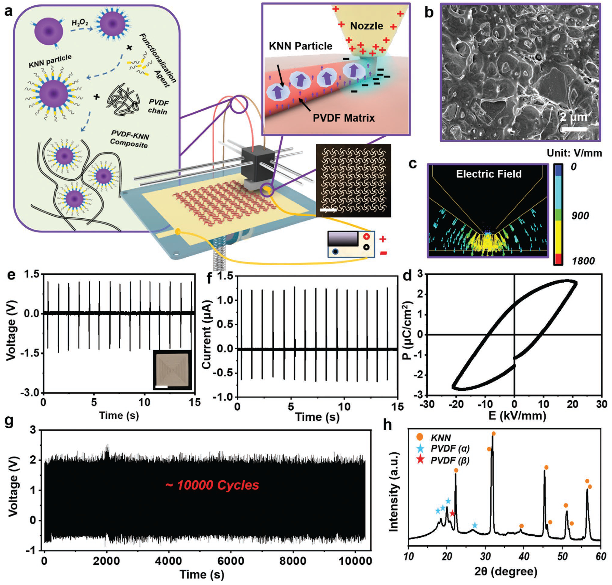
Electric field-assisted 3D-printing. a) Schematic illustration of the electric field-assisted FDM 3D printing system. Left inset: The ferroelectric filament consists of surface functionalized KNN nanoparticles and PVDF polymer matrix. Top right inset: Rapid poling during printing under an adjustable inner-built electric field. Bottom right inset: A digital image of 3D printed sinusoidal film with high fidelity. Scale bar is 1 cm. b) Cross-sectional SEM image of the as-printed film. c) Finite element analysis (FEA) simulation of the electric field around nozzle during 3D printing process. d) Polarization–electric field (P–E) hysteresis loop measured from a 3D printed ferroelectric composite film at room temperature. e) Voltage output and f) current output of a 3D printed film under a mechanical stimulus of 30 N at 1 Hz. The scale bar in the inset in e) is 5 mm. g) Long-term stability of printed film under a mechanical stimulus of 30 N at 1 Hz. h) XRD spectrum of as-printed PVDF-KNN composite film.
To align the dipoles of the as-printed materials, an adjustable electric field in the range of 0.5–4 kV mm−1 was applied between the print core and the bottom plate (Movie S1 and Figure S5, Supporting Information). Finite element simulation revealed that a rather high electric field was concentrated at the nozzle tip region (Figure 1c). In addition, the printing process was performed at a relatively high temperature of 250 °C to melt the ferroelectric composite, where a significantly lower coercive field could be anticipated.[15] The concentrated electric field and high processing temperature are favorable for aligning the ferroelectric dipoles instantaneously in the just-extruded material. Therefore, rapid poling was achieved as the printing progresses.
To validate the poling capability during printing, one layer of square film (1.5 cm × 1.5 cm,) was printed under a voltage of 800 V. The ferroelectricity of the as-printed film was confirmed by polarization hysteresis measurement, and an apparent hysteresis curve intimating net dipole was observed (Figure 1d). Therefore, the film was able to generate a stable piezoelectric peak-to-peak voltage output of ≈2.7 V (Vpp) (Figure 1e) and a short-circuited current of 1.25 mA (Figure 1f) under an external force load of 30 N (peak load). This output was at the same level of the reported values of ferroelectric PVDF (≈3 V under 30 N)[16] and poly-L-lactic acid film (≈0.7 V under 30 N),[17] validating a comparable piezoelectricity akin to common piezo-polymers. Although the poling time was very short on each printing spot, the dipole alignment was rather stable. As shown in Figure 1g, the Vpp output remained at ≈2.7 V for >10 000 cycles under a repeating force application (30 N). The considerable and stable piezoelectric output confirmed that the KNN-PVDF composite was able to be rapidly poled in situ during 3D printing and thus bypass the critical challenge of postfabrication high-voltage poling. As thus, this development enabled the creation of complex ferroelectric 3D geometries, such as chiral helix and spiral with desirable piezoelectric outputs (Figure S6, Supporting Information).
The superb piezoelectric property of the as-printed KNN-PVDF composite film was attributed to the synergistic contribution from both ferroelectric KNN particles and PVDF matrix. When barium titanate (BTO), another representative lead-free and biocompatible piezoceramics, was used in place of KNN, although BTO has even higher piezoelectric coefficient than that of KNN, its low curie temperature (≈120 °C) prevented it from high-temperature printing processes.[13b,c] As a result, the film printed by BTO-PVDF composite only yielded a Vpp of ≈0.3 V (Figure S7a,b, Supporting Information), which was mostly contributed by a small amount of β-phase PVDF. β-phase PVDF could be formed due to the fast cooling rate and further poled under the high electric field during printing. The characterize peak of the β-phase at 20.8° could be clearly observed from the X-ray diffraction (XRD) spectra of both printed PVDF and KNN-PVDF (Figure S7c, Supporting Information, and Figure 1h). However, without KNN, the printed PVDF film only yielded an output of ≈0.3 V (Figure S7, Supporting Information). When a nonpiezoelectric polylactic acid (PLA) was used as the matrix together with KNN, a significantly lower piezoelectric output of 1.7 V was received, although the printability was not influenced (Figure S7a,b, Supporting Information). These comparisons revealed that KNN made the major contribution to the polarization; while the PVDF matrix also played a critical role in assisting the overall polarization (inset of Figure 1a), which was further evidenced by electrostatic force microscopy (EFM) examination (Figure S8, Supporting Information).
2.2. Control of the Piezoelectricity by Printing Parameters
The piezoelectricity of printed objects was controllable by the 3D printing parameters, allowing for property optimization for final applications. To show the influence of the poling electric field, single-layer films (1.5 cm × 1.5 cm) were printed under a voltage ranging from −800 to 800 V. Figure 2a shows that the absolute value of the piezoelectric coefficient d33 (|d33|) of the as-printed film gradually increased from 0 to ≈12 pC N−1 as the absolute value of voltage (|Vpp|) rose from 0 to 800 V. Accordingly, the output Vpp under a 30 N force increased from ≈60 mV to ≈2.7 V. The direction of poling voltage dictated the object’s polarity, which was exemplified by two samples fabricated under 400 and −400 V, respectively. They both generated similar electric output of ≈1.6 V in response to a 30 N force; whereas the phases of voltage signals were completely opposite (Figure S9, Supporting Information). The different polarity was also confirmed by EFM phase imaging (Figure 2b), where the surface of negatively poled sample showed a nearly 180° phase reverse compared to the positively poled sample. All the results confirmed that the polarity of the printed objects could be easily adjusted by varying the poling electric field.
Figure 2.
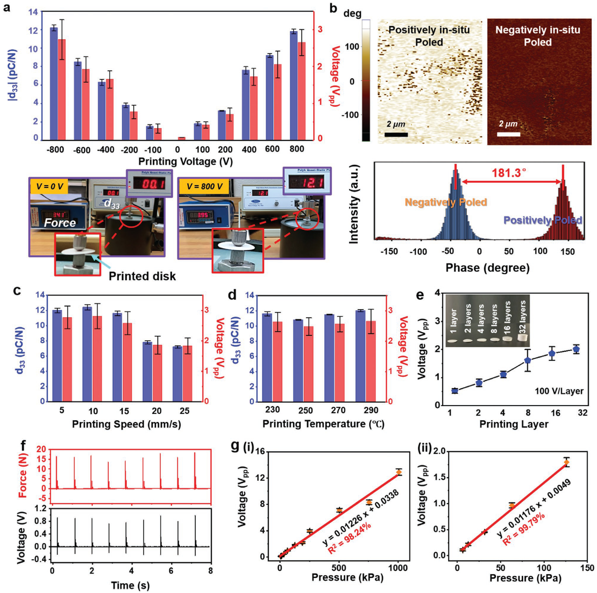
Piezoelectricity control and pressure sensing performance. a) The absolute value of piezoelectric coefficient d33 and peak-to-peak voltage output as a function of printing voltage. Data are expressed as mean ± standard deviation (SD) (n = 3). Digital images are piezoelectric coefficient measurement of printed disks under different voltage by piezometer (d33 meter). b) The EFM phase images of films printed under 400 and −400 V. The lower panel is phase angle revealing 181.3° reverse between positively poled and negatively poled samples. The piezoelectric coefficient d33 and peak-to-peak voltage output as a function of c) printing speed and d) printing temperature, Data are expressed as mean ± SD (n = 3). e) Peak-to-peak voltage output as a function of printing layer. Inset is printed cylinders with different layers at a constant printing speed of 10 mm s−1. Each layer has a thickness of 200 μm. Data are expressed as mean ± SD (n = 3). f) Real-time voltage output of printed piezoelectric disk corresponding to various applied force. g) Linear fit of output voltage and applied pressure in the range of (i) 6.2 kPa to 1.0 MPa and (ii) 6.2–140 kPa. Data are expressed as mean ± SD (n = 3).
The printing speed was another factor that would impact the piezoelectric property. As illustrated in Figure 2c, under the voltage of 800 V, the d33 kept stable around 12.1 pC N−1 when the printing speed was set below 10 mm s−1. The d33 slightly dropped to 11.5 pC N−1 as the speed was boosted to 15 mm s−1. When the printing speed was further increased to 25 mm s−1, the d33 dramatically fell to 7.2 pC N−1, as well as the generated voltage. This relationship was primarily due to the shortened poling time and reduced dipole alignment at fast printing rate. The printing rate of 15 mm s−1 significantly outperformed other approaches that required a printing speed of 1 mm s−1 or less to achieve desired functionality.[18] Therefore, potential of achieving high-throughput manufacture could be expected. Additionally, the nozzle temperature within the range of 230–290 °C had negligible influences to the piezoelectric performance. As revealed in Figure 2d, the piezoelectric constant and output voltage stabilized at ≈12 pC N−1 and ≈2.6 V, respectively, within the testing temperature range. No obvious correlation between bed temperature and piezoelectricity was observed (Figure S10, Supporting Information). Therefore, the electric field-assisted 3D printing could be effectively implemented under a wide range of printing conditions, which makes it versatile for different materials and compositions.
After fundamental testing on single-layer films, the object thickness was scaled to demonstrate the 3D printing capability. The voltage output as a function of object height is shown in Figure 2e. Under an electric field of 100 V per layer (equals to 500 V mm−1 with each layer of 200 μm in thickness), the sample was printed from 1 layer to 32 layers at a constant printing speed of 10 mm s−1. Correspondingly, the output Vpp monotonically increased from 0.5 to 2 V (Figure S11, Supporting Information); whereas the increasing rate was slowly saturated as the thickness was more than eight layers. This nonlinear relationship was possibly due to uneven stress distribution in polymer matrix at large thickness when pulsed force was applied (Figure S12, Supporting Information). Regardless, the as-printed 3D ferroelectric object showed an excellent sensibility, particularly to small pressure variations. A printed ferroelectric disk (1.5 cm diameter and 1.2 mm thickness) was used to demonstrate the sensing capability (Figure S13, Supporting Information). As shown in Figure 2f, the generated voltage output exactly followed the amplitude change of the applied pressure. Furthermore, a series of pressures over a large range from 6.2 kPa to 1.0 MPa was exerted on the ferroelectric disk, and corresponding Vpp outputs were measured to be from 0.11 to 12.9 V. Correlation between voltage and pressure was plotted in Figure 2g–i, from which an excellent linearity (R2 > 0.98) with a slope (i.e., force sensitivity) of 12.26 mV kPa−1 was obtained from the plot. The linearity was even better at lower pressure of 140 kPa and less (Figure 2g–ii, R2 > 0.99). Such an excellent linearity suggested a strong potential for force and pressure sensoring.
2.3. Artificial Artery Development
The successful 3D printed ferroelectric materials with excellent force/pressure sensitivity opened up the promises for developing smart artificial artery with self-powered sensing capability. As presented in Figure 3a, the polarized tube consisting of sinusoidal lattices with a thickness of 0.2 mm was printed with poling direction normal to the surface under a speed of 10 mm s−1. The detailed geometry of the sinusoidal lattice was shown in Figure S14 in the Supporting Information. Biocompatible silver paste was applied on the inner and exterior sides as electrodes with a thickness around 0.05 mm. The as- fabricated cylindrical network was encapsulated by polydimethylsiloxane (PDMS) with a thickness of ≈2 mm to form the final artificial artery structure. Although the ferroelectric composite had a higher mechanical modulus compared to pure PVDF due to the involvement of ceramic components, the sinusoidal structure design with soft package could effectively lower the modulus to the level of biological tissues/organs. Evidenced by tensile (Figure 3b) and bending tests (Figure 3c), the artificial artery exhibited a tissue-comparable stretchability and flexibility with a significantly lowered tensile modulus of 5.68 MPa (elongation of ≈38%) and flexural modulus of 10.35 MPa. For comparison, the unstructured composite film and pristine PVDF film printed under the same conditions with the same thickness and size exhibited a tensile modulus of 1.17 and 0.76 GPa, and a flexural modulus of 1.32 and 0.82 GPa, respectively. The mechanical property of the artificial arteries fitted well within the modulus range of human arteries.[19]
Figure 3.
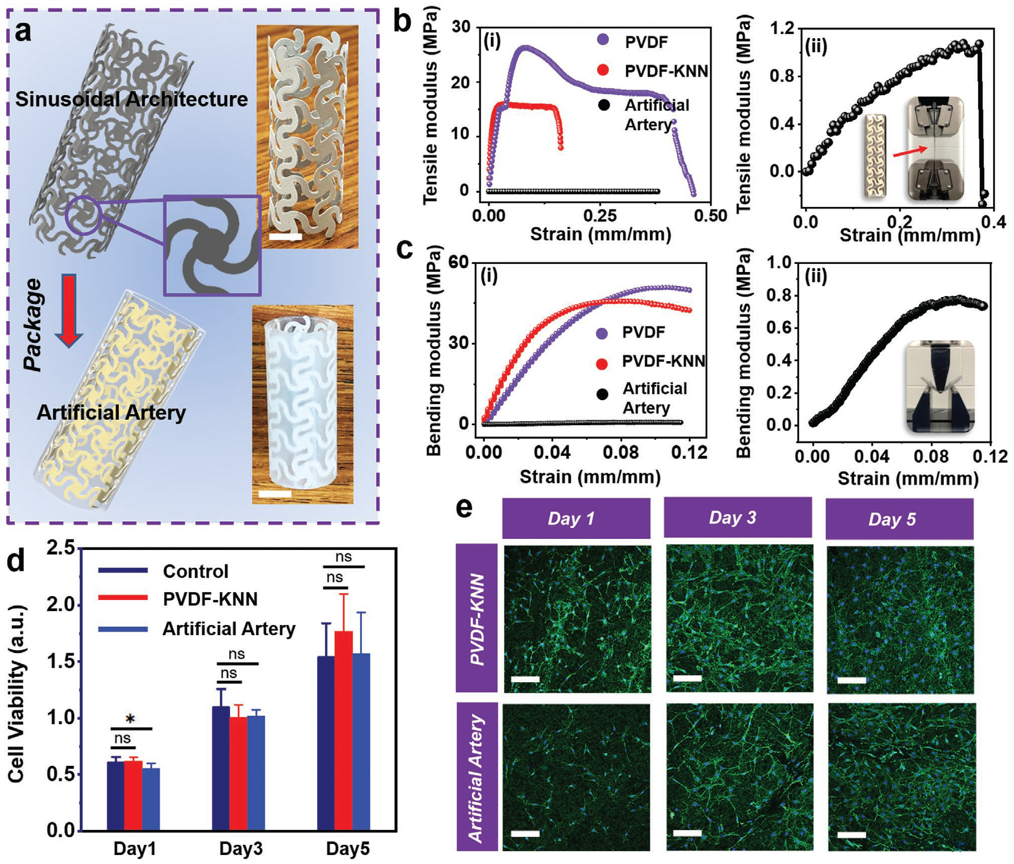
Artificial artery development and characterization. a) Schematic illustration of artificial artery consisting of printed piezoelectric tube with sinusoidal lattice and PDMS package. Insets are digital images of piezoelectric tube architecture and artificial artery. The scale bar is 5 mm. b) Tensile modulus and c) bending modulus of pristine PVDF film (purple), PVDF-KNN composite film (red), and artificial artery (black). Enlarged curves of artificial artery are shown in (ii). Insets are photos of the testing setup. d) Cell viability as a function of time. The control group refers cells cultured in a culture dish. Data are expressed as mean ± SD (n = 6). The *p < 0.05 (statistically significant) and ns = not significant. e) Fluorescence microscope image of 3T3 fibroblast cells cultured on printed PVDF-KNN film and artificial artery. The scale bar is 100 μm.
The artificial artery was also expected to be biocompatible, as it only consisted of components (PVDF, KNN, and PDMS) that have been proved biocompatible.[20] The biocompatibility of the as-fabricated artery was first examined by analyzing the viability of 3T3 fibroblast cells on the top of printed ferroelectric film and PDMS-packaged surface. 3-(4,5-Dimethylthiazol-2yl)-2,5-diphenyl-2H-tetrazolium bromide (MTT) assay was performed to evaluate the cellular metabolic activity as a reference for cell growth/proliferation. As shown in Figure 3d, the cell viability of printed films and PDMS-packaged surface did not exhibit significant difference compared to the control group in five days. The cell morphology observed under fluorescence microscopy did not display any significant dissimilarity between all groups as well (Figure 3e). These results confirmed that the artificial artery materials were nontoxic and biocompatible.
An artificial circulation system was then built to demonstrate the self-powered blood pressure sensing capability of the 3D printed artificial artery. The artificial artery was integrated with a computer-controlled syringe pump to mimic heart beats (Figure S15 and Movie S2, Supporting Information). The programmable back-and-forth linear motions (Figure S15, Supporting Information) of the actuator connected to the syringe pump would pump the fluid in and out from the artificial artery, which induced periodic pressure change inside. As shown by the schematics in Figure 4a, in response to the internal pressure change, a longitudinal strain could be induced in the ferroelectric wall, and thus piezoelectric potential was generated between the two electrodes. The piezoelectric responses were confirmed by the opposite output phase when the electrodes connection was switched (Movies S3 and S4, Supporting Information).
Figure 4.
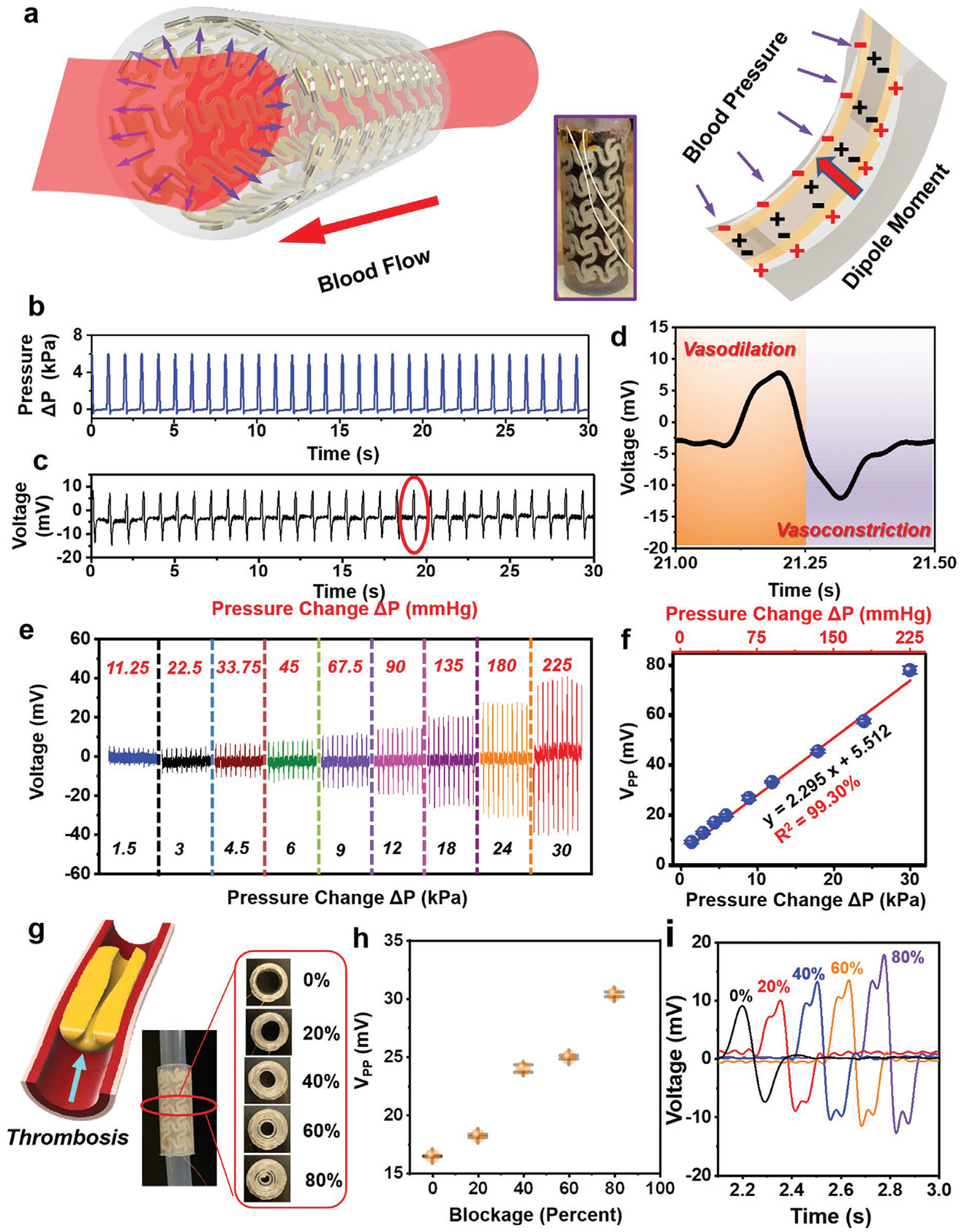
Ex vivo tests for artificial artery system. a) Schematic illustration of the piezoelectric effect in artificial artery in response to blood pressure. b) Real-time pressure change inside the artery when PBS-simulated blood flow driven by a syringe pump. c) Voltage output of the artery under blood flow. d) Detailed voltage response in the process of vasodilation and vasoconstriction from encircled area in (c). e) Voltage response of the artery as a function of pressure change. f) Linear fitting of peak-to-peak voltage and pressure change. Data are expressed as mean ± SD (n = 3). g) Partial occlusion (0–80%) of the artery system through PDMS-simulated thrombosis. Left panel is a schematic illustration of thrombosis formation in artery. h) Peak-to-peak voltage change as a function of artery blockage. Data are expressed as mean ± SD (n = 3). i) Comparison of detailed single voltage envelope under different levels of occlusion.
Considering an average adult having a diastolic pressure of 80 mmHg and a systolic pressure of 120 mmHg, the arterial pressure fluctuates within pressure change around 5.33 kPa (40 mmHg). Based on this information, the artificial artery system was filled with red-colored phosphate-buffered saline (PBS) (with dye) to simulate blood, and an average ΔP of ≈6 kPa was applied by the syringe pump at a frequency of 1 Hz (equal to a heart rate of 60 beats per minute) to imitate the normal human activity (Figure 4b and Movie S5, Supporting Information). As shown in Figure 4c, an output Vpp of ≈19.55 mV was yielded following the pressure oscillating, with a high stability over 10 000 cycles (Figure S15, Supporting Information). Specifically, during the process of vasodilation (the expansion of artery due to pump-in blood), a positive voltage was produced; while a negative voltage signal was detected in the process of vasoconstriction (artery contract due to pump-out blood) (Figure 4d and Movie S6, Supporting Information). The polarization of voltage was consistent with the poling direction during 3D printing. To further investigate the pressure sensitivity, a series of ΔP was applied to the artificial artery system by altering the pumping volume of syringe. As shown in Figure 4e, when the applied ΔP was boosted from 1.5 kPa (11.25 mmHg) to 30 kPa (225 mmHg), the Vpp increased from 8.91 to 77.71 mV accordingly. An exceptional linearity (R2 = 0.9930) between voltage and ΔP was obtained with a sensitivity of 2.295 mV kPa−1 (0.306 mV mmHg−1) (Figure 4f), which evidenced that a complex 3D structure would not compromise the sensing accuracy, although soft PDMS encapsulation could lower the output voltage at the same pressure change (12.26 mV kPa−1 from the film morphology). This ex vivo tests revealed an intriguing capability of performing self-powered real-time sensing of blood pressure inside artificial artery.
As expected, the self-powered pressure sensing capability was feasible to prevent implant failure as the partial occlusion (e.g., thrombosis) of artery could be revealed by the voltage signal. Different percentages of occlusion (0–80%) in the artery were created by inserting PDMS-simulated thrombosis (Figure 4g), and the voltage signals were recorded accordingly. As presented in Figure 4h and Figure S16 in the Supporting Information, the amplitude of voltage was not significantly increased until 40% occlusion was created. Further occlusion up to 80% doubled the voltage output to ≈32 mV, indicating probable hypertension at the late stage of thrombosis. The early thrombosis could be identified by the voltage profile (Figure 4i). Two adjacent voltage peaks were found in each voltage envelop after thrombosis formation. This was possibly due to the asymmetric artery movement as a result of the different blood flows/pressures pattern at two sides of the thrombosis. While the normal artery has one simple movement of expansion and contraction, the occluded artery will have an extra movement of surrounding tissue near the thrombosis due to uneven pressure distribution (Figure S17, Supporting Information). Therefore, this smart artificial artery could provide a unique way of early detection of vascular diseases and prevent implant failure by providing real-time local pressure monitoring.
3. Conclusion
This work developed a printable ferroelectric biocomposite capable of being quickly polarized and reshaped into devised object with a high piezoelectric effect (≈12.1 pC N−1) and excellent pressure sensibility capability (12.26 mV kPa−1), through an electric field-assisted FDM technology. Synergistic effect from ferroelectric polymer matrix (PVDF) and particles (KNN) yielded a superb performance over other akin composites (e.g., PLA-BTO, PLA-KNN and PVDF-BTO). The marriage of electroactive material compositing and additive manufacturing technology with in situ poling capability provides a versatile avenue toward creating smart artificial biological systems with real-time sensing function. An artificial artery system was thus printed and demonstrated precise sensitivity to normal human blood pressure range. Excellent linearity between produced electricity and pressure were obtained (2.295 mV kPa−1, R2 > 0.99). This result suggested a promising capability of real-time monitoring blood flow pressure, allowing effective prevention of common failure in vascular implants due to undetected complications. This approach of 3D printing polarized ferroelectric biomaterial could also be further extended by combining with advanced imaging techniques such as CT and 3D reconstructions to quickly built up artificial organs with integrated multifunctionality.
4. Experimental Section
Preparation of Ferroelectric Particles:
KNN (K0.5Na0.5NbO3) was synthesized by a conventional solid-state reaction method. Raw Materials including potassium carbonate (K2CO3, >99%, Sigma), sodium carbonate (Na2CO3, >99.5%, Sigma), and niobium oxide (Nb2O5, >99.9%, Alfa Aesar) were uniformly mixed in in a molar ratio of 1:1:2 and dried at 210 °C for 2 h to remove absorbed moisture. The dried mixture was hand milled for 4 h and then calcined at 1100 °C in a Muffle furnace for 4 h followed by slowly cooling down to room temperature to form high-purity KNN ceramics. Tetragonal Barium Titanate BTO (BaTiO3) particles with diameter around 2 μm were purchased from Sigma-Aldrich (>99.5%).
Surface Modification of Particles:
KNN ceramics were hand milled for another 1 h to form microparticles. The microparticles were first refluxed with H2O2 solution (30%) at 105 °C for 2 h to add hydroxyl group onto the surface. The collected samples through centrifuge were rinsed with deionized water for three times and dried in oven. The dried samples were further surface modified through refluxing with MPS (2%) in methanol solution at 70 °C for 4 h. Surface-treated samples were collected, rinsed with methanol, and dried in oven at 80 °C overnight. The surface treatment of BTO particles also follows the same procedures.
Preparation of Composite:
Surface-modified particles (KNN or BTO) were mixed with polymer pellets (Kynar 720 PVDF or Ingeo Biopolymer 3D850 PLA) at a volume ratio of 3.5 to 6.5. Mixtures could be either directly grinded into even compositions by an SPEX 6875 Cryogenic Grinder; or added into N,N-dimethylformamide (>99.8%, Sigma) solvent (Chloroform for PLA) at 80 °C for 1 h with stirring to form even solution (25 wt% concentration) which would be casted into glass dish to form composite film after evaporating solvent at 70 °C overnight, and then the films were grinded into fine powders by an SPEX 6875 Cryogenic Grinder.
Filament Fabrication:
With grinded fine powders as raw materials, the ferroelectric filament with constant diameter around 2.7 mm was extruded through a customized polymer extruder (built based on Filastruder kit with 3.00 mm nozzle) at 170 °C and collect by a customized winder (built based on Filawinder kit) with spool. A laser sensor was utilized for filament diameter control.
3D. Printing:
Ferroelectric composite was printed on customized fused deposition modeling (FDM) 3D printers. An inner electric field of 0.5 – 4 kV mm−1 was built by connecting the positive electrode of a high voltage source (30 kV, 10 W) to a print core while negative electrode contacting copper foil attached on the build plate. A thin layer of polyvinyl alcohol (PVA) (Elmer’s Disappearing Purple Glue Stick) was applied on the copper foil to enhance the adhesion of first printing layer. Complex 3D structure was coprinted with PVA/poly(methyl methacrylate) filament as supporting materials followed by rinsing with water/chloroform to completely remove the supports. Silver paste (EPO-TEK H20E) was applied as electrodes.
Composition/Structure Analysis:
X-ray diffraction patterns of KNN microparticles, PVDF, and PVDF-KNN were acquired from the Bruker D8 Discovery with Cu Kα radiation. XPS spectrum of KNN microparticles was acquired using a Thermo Scientific K-alpha XPS instrument. SEM observations of PVDF/KNN composite were performed on a Zeiss LEO 1530 field-emission microscope.
Dipole/Piezoelectricity Analysis:
EFM images of 3D printed films were obtained using an XE-70 Park System. The direct piezoelectric d33 coefficients of 3D-printed films were measured using a quasistatic d33 piezometer (ZJ-3A, Institute of Acoustics, Chinese Academy of Sciences, Beijing, China). The polarization–electric field (P–E) curve of 3D-printed film was evaluated on a precision material analyzer (Premier II, Radiant Technologies Inc., Albuquerque, NM, USA).
Electric Characterizations:
The voltage outputs of 3D printed film were measured by connecting probes of a multimeter (DMM 6500, Keithley) to the top and bottom electrodes. The short-circuit current was measured by a low-noise current preamplifier (Stanford Research Systems, model SR570) connected with LabVIEW system in computer.
Force/Pressure Sensitivity Analysis:
A force of 30 N was applied to the 3D printed films covered with electrodes by a permanent magnet shaker (LV201, M4-CE) at 1 Hz controlled by a function generator (DS 345, Stanford Research Systems). The force was quantified by a portable sensor measurement system (compression piezoelectric sensor (CL-YD-303) integrated with a four-channel dynamic signal acquisition module (NI 9234) and compact data acquisition chassis (NI, cDAQ-9171)). The real-time pressure of artificial artery system was quantified by a force resistive sensor (FSR 402, Interlink Electronics).
Mechanical Characterizations:
The dynamic modulus of 3D printed PVDF-KNN sample and 3D printed pure PVDF sample with equal dimension (1 cm × 6 cm × 0.2 mm) was measured by an Rheometrics Solids Analyzer III dynamic mechanical analyzer. The tensile modulus of 3D printed dog-bones was measured by tensile test in MTS Criterion Model 43. The compressive modulus of 3D printed tube was measured by compression test in MTS Criterion Model 43. The flexural modulus of 3D printed rectangular beam was measured by three-point bending test in MTS Criterion Model 43.
Artificial Artery System Actuation:
3D printed artificial artery system was driven by a computer-controlled actuator (LinMot), the open-circuit voltage of the artificial printed artery system was measured by the low-noise voltage preamplifier (Stanford Research Systems, model SR560).
MTT Assay:
National Institute of Health 3T3 fibroblasts (human umbilical vein endothelial cells, CAMBREX) were cultured in a complete growth media that comprised high glucose Dulbecco’s modified Eagle medium with l-glutamine, supplemented with 15% fetal bovine serum (Hyclone; Thermo Fisher Scientific). The cells were seeded into 96-well culture plates with 3D printed circular films, maintained at 37 °C in a humidified atmosphere in the presence of 5% CO2, and the culture medium was changed every day. After up to 4 d, MTT (3-(4,5-dimethylthiazol-2-thiazolyl)-2,5-diphenyl-2H-tetrazolium bromide) assay (ThermoFisher Scientific) was performed to examine cell viability. MTT solution (100 μL) was added to each well. After 4 h of incubation, the medium was removed, and dimethyl sulfoxide (500 mL per well) was added to dissolve the precipitated fomazan. The optical density (n = 3) of the solution was evaluated using a microplate spectrophotometer at a wavelength of 490 nm.
Cell Morphology and Immunofluorescence Staining:
After 3T3 cells were cultured on the 3D printed film with different polarities or cell plates (control group) in 24-well plates, the cell morphology was observed directly using an upright confocal microscope (Nikon A1R high definition (HD) Upright Multiphoton/Confocal microscope). The cytoskeleton and nucleus were stained with Flash Phalloidin Green 488 (BioLegend) and blue fluorescent Hoechst (352/461 nm) (Thermo Fisher Scientific), respectively. Reconstitute the Flash Phalloidin Green 488 with 1.5 mL of methanol to make 300 units stock solution. The samples were fixed with 2–4% formaldehyde for 15 min and then rinsed three times with prewarmed PBS. The samples were incubated with Flash Phalloidin Green 488 (diluting 300 mL stock solution 1:50 in 1X PBS) and Hoechst (50 × 10−9 m) for 30 min at 37 °C. After staining, the cells were rinsed with prewarmed buffer for three times and imaged samples using a Nikon A1R HD Upright Multiphoton/Confocal microscope.
Finite Element Analysis (FEA):
The voltage potential and inner electric field during 3D printing was simulated by the commercial FEA software ANSYS 19.2 Version.
Statistical Analysis:
The data were taken from at least three independent experiments and all obtained data was expressed as mean value ± standard deviation (SD). Statistical analysis was performed by using GraphPad Prism 8.4 software with a one-way analysis of variance method. Single asterisk and abbreviation ns represent P < 0.05 and P > 0.05, respectively. Only P < 0.05 was considered statistically significant.
Supplementary Material
Acknowledgements
Jun Li is grateful for the support of Johnson Controls fellowship. This publication was supported by the National Institute of Biomedical Imaging and Bioengineering of the National Institutes of Health under Award Number R01EB021336. The content is solely the responsibility of the authors and does not necessarily represent the official views of the National Institutes of Health.
Footnotes
Supporting Information
Supporting Information is available from the Wiley Online Library or from the author.
Conflict of Interest
The authors declare no conflict of interest.
Contributor Information
Fan Yang, Department of Materials Science and Engineering, University of Wisconsin–Madison, Madison, WI 53706, USA.
Hao Wei, Department of Radiology and Medical Physics, University of Wisconsin–Madison, Madison, WI 53705, USA.
Cheng Li, Laboratory of Dielectric Materials, School of Materials Science and Engineering, Zhejiang University, Hangzhou 310027, China.
Yongjun Wu, Laboratory of Dielectric Materials, School of Materials Science and Engineering, Zhejiang University, Hangzhou 310027, China.
Weibo Cai, Department of Radiology and Medical Physics, University of Wisconsin–Madison, Madison, WI 53705, USA.
Xudong Wang, Department of Materials Science and Engineering, University of Wisconsin–Madison, Madison, WI 53706, USA.
References
- [1].a) Pashneh-Tala S, MacNeil S, Claeyssens F, Tissue Eng., Part B 2016, 22, 68; [DOI] [PMC free article] [PubMed] [Google Scholar]; b) Farber A, Engl N. J. Med 2018, 379, 171; [DOI] [PubMed] [Google Scholar]; c) Chlupáč J, Filova E, Bačáková L, Physiol. Res 2009, 58, S119. [DOI] [PubMed] [Google Scholar]
- [2].Nagpal A, Sohail MR, Curr. Infect. Dis. Rep 2011, 13, 317. [DOI] [PubMed] [Google Scholar]
- [3].a) Ercolani E, Del Gaudio C, Bianco A, Tissue Eng J. Regener. Med 2015, 9, 861; [DOI] [PubMed] [Google Scholar]; b) Li Z, Li X, Xu T, Zhang L, Appl. Sci 2019, 9, 2864. [Google Scholar]
- [4].a) Melchiorri AJ, Hibino N, Best C, Yi T, Lee Y, Kraynak C, Kimerer LK, Krieger A, Kim P, Breuer CK, Adv. Healthcare Mater 2016, 5, 319; [DOI] [PMC free article] [PubMed] [Google Scholar]; b) Skylar-Scott MA, Uzel SG, Nam LL, Ahrens JH, Truby RL, Damaraju S, Lewis JA, Sci. Adv 2019, 5, eaaw2459; [DOI] [PMC free article] [PubMed] [Google Scholar]; c) Elomaa L, Yang YP, Tissue Eng., Part B 2017, 23, 436. [DOI] [PMC free article] [PubMed] [Google Scholar]
- [5].a) Prichard HL, Manson RJ, DiBernardo L, Niklason LE, Lawson JH, Dahl SL, J. Cardiovasc. Transl. Res 2011, 4, 674; [DOI] [PMC free article] [PubMed] [Google Scholar]; b) Bosman P, Blankestijn P, Van der Graaf Y, Heintjes R, Koomans H, Eikelboom B, Group SS, Eur. J. Vasc. Endovasc. Surg 1998, 16, 126. [DOI] [PubMed] [Google Scholar]
- [6].a) Oresanya L, Makam AN, Belkin M, Moneta GL, Conte MS, J. Vasc. Surg 2014, 59, 996; [DOI] [PubMed] [Google Scholar]; b) Norgren L, Hiatt WR, Dormandy JA, Nehler MR, Harris KA, Fowkes FGR, J. Vasc. Surg 2007, 45, S5. [DOI] [PubMed] [Google Scholar]
- [7].a) Veith F, Weiser R, Gupta S, Ascer E, Scher LA, Samson R, White-Flores S, Sprayregen S, J. Cardiovasc. Surg 1984, 25, 381; [PubMed] [Google Scholar]; b) Gupta SK, Dietzek AM, Veith FJ, Torres M, Kram HB, Wengerter KR, Am. J. Surg 1990, 160, 182. [DOI] [PubMed] [Google Scholar]
- [8].Neville RF, Gupta SK, Kuraguntla DJ, J. Vasc. Surg 2017, 65, 1793. [DOI] [PubMed] [Google Scholar]
- [9].Hinchet R, Yoon H-J, Ryu H, Kim M-K, Choi E-K, Kim D-S, Kim S-W, Science 2019, 365, 491.. [DOI] [PubMed] [Google Scholar]
- [10].Natta L, Mastronardi V, Guido F, Algieri L, Puce S, Pisano F, Rizzi F, Pulli R, Qualtieri A, De Vittorio M, Sci. Rep 2019, 9, 8392. [DOI] [PMC free article] [PubMed] [Google Scholar]
- [11].a) Li J, Kang L, Yu Y, Long Y, Jeffery JJ, Cai W, Wang X, Nano Energy 2018, 51, 728; . [DOI] [PMC free article] [PubMed] [Google Scholar]; b) Li J, Long Y, Yang F, Wang X, Curr. Opin. Solid State Mater. Sci 2020, 24, 100806; [DOI] [PMC free article] [PubMed] [Google Scholar]; c) Zhang H, Zhang X-S, Cheng X, Liu Y, Han M, Xue X, Wang S, Yang F, Smitha A, Zhang H, Nano Energy 2015, 12, 296; [Google Scholar]; d) Dagdeviren C, Yang BD, Su Y, Tran PL, Joe P, Anderson E, Xia J, Doraiswamy V, Dehdashti B, Feng X, Proc. Natl. Acad. Sci. USA 2014, 111, 1927; [DOI] [PMC free article] [PubMed] [Google Scholar]; e) Dagdeviren C, Shi Y, Joe P, Ghaffari R, Balooch G, Usgaonkar K, Gur O, Tran PL, Crosby JR, Meyer M, Nat. Mater 2015, 14, 728; [DOI] [PubMed] [Google Scholar]; f) Zheng Q, Shi B, Fan F, Wang X, Yan L, Yuan W, Wang S, Liu H, Li Z, Wang ZL, Adv. Mater 2014, 26, 5851; [DOI] [PubMed] [Google Scholar]; g) Ouyang H, Liu Z, Li N, Shi B, Zou Y, Xie F, Ma Y, Li Z, Li H, Zheng Q, Nat. Commun 2019, 10, 1821. [DOI] [PMC free article] [PubMed] [Google Scholar]
- [12].a) Yao D, Cui H, Hensleigh R, Smith P, Alford S, Bernero D, Bush S, Mann K, Wu HF, Chin-Nieh M, Adv. Funct. Mater 2019, 29, 1903866; [Google Scholar]; b) Cui H, Hensleigh R, Yao D, Maurya D, Kumar P, Kang MG, Priya S, Zheng XR, Nat. Mater 2019, 18, 234; [DOI] [PubMed] [Google Scholar]; c) Kim K, Zhu W, Qu X, Aaronson C, McCall WR, Chen S, Sirbuly DJ, ACS Nano 2014, 8, 9799; . [DOI] [PubMed] [Google Scholar]; d) Chen Z, Song X, Lei L, Chen X, Fei C, Chiu CT, Qian X, Ma T, Yang Y, Shung K, Nano Energy 2016, 27, 78. [Google Scholar]
- [13].a) Wu J, Xiao D, Zhu J, Chem. Rev 2015, 115, 2559; [DOI] [PubMed] [Google Scholar]; b) Zheng T, Wu J, Xiao D, Zhu J, Prog. Mater. Sci 2018, 98, 552; [Google Scholar]; c) Rödel J, Jo W, Seifert KT, Anton EM, Granzow T, Damjanovic D, J. Am. Ceram. Soc 2009, 92, 1153. [Google Scholar]
- [14].a) Porter DA, Hoang TV, Berfield TA, Addit. Manuf 2017, 13, 81; [Google Scholar]; b) Shepelin NA, Glushenkov AM, Lussini VC, Fox PJ, Dicinoski GW, Shapter JG, Ellis AV, Energy Environ. Sci 2019, 12, 1143; [Google Scholar]; c) Martins P, Lopes A, Lanceros-Mendez S, Prog. Polym. Sci 2014, 39, 683. [Google Scholar]
- [15].a) Zhou D, Guan Y, Vopson MM, Xu J, Liang H, Cao F, Dong X, Mueller J, Schenk T, Schroeder U, Acta Mater. 2015, 99, 240; [Google Scholar]; b) Zhang Y, Chen Z, Cao W, Zhang Z, Appl. Phys. Lett 2017, 111, 172902; [Google Scholar]; c) Ren P, Liu Z, Wei M, Liu L, Shi J, Yan F, Fan H, Zhao G, J. Eur. Ceram. Soc 2017, 37, 2091. [Google Scholar]
- [16].He H, Fu Y, Zhao T, Gao X, Xing L, Zhang Y, Xue X, Nano Energy 2017, 39, 590. [Google Scholar]
- [17].Curry EJ, Ke K, Chorsi MT, Wrobel KS, Miller AN, Patel A, Kim I, Feng J, Yue L, Wu Q, Proc. Natl. Acad. Sci. USA 2018, 115, 909. [DOI] [PMC free article] [PubMed] [Google Scholar]
- [18].a) Muth JT, Vogt DM, Truby RL, Mengüç Y, Kolesky DB, Wood RJ, Lewis JA, Adv. Mater 2014, 26, 6307; [DOI] [PubMed] [Google Scholar]; b) Postiglione G, Natale G, Griffini G, Levi M, Turri S, Composites, Part A 2015, 76, 110; [Google Scholar]; c) Cui Z, Han Y, Huang Q, Dong J, Zhu Y, Nanoscale. 2018, 10, 6806. [DOI] [PubMed] [Google Scholar]
- [19].a) Ebrahimi AP, J. Vasc. Interv. Radiol 2009, 2, 155; [PMC free article] [PubMed] [Google Scholar]; b) Dahl SL, Rhim C, Song YC, Niklason LE, Ann. Biomed. Eng 2007, 35, 348; [DOI] [PMC free article] [PubMed] [Google Scholar]; c) Leguy C, Bosboom E, Gelderblom H, Hoeks A, Van De Vosse F, Med. Eng. Phys 2010, 32, 957. [DOI] [PubMed] [Google Scholar]
- [20].a) Yu S-W, Kuo S-T, Tuan W-H, Tsai Y-Y, Wang S-F, Ceram. Int 2012, 38, 2845; [Google Scholar]; b) Bélanger MC, Marois Y, J. Biomed. Mater. Res 2001, 58, 467. [DOI] [PubMed] [Google Scholar]
Associated Data
This section collects any data citations, data availability statements, or supplementary materials included in this article.