Abstract
Surface area and surface active sites are two important key parameters in enhancing the gas sensing as well as photocatalytic properties of the parent material. With this motivation, herein, we report a facile synthesis of Reduced Graphene Oxide/Tungsten Oxide RGO/WO3 hierarchical nanostructures via simple hydrothermal route, and their validation in accomplishment of improved H2S sensing and highly efficient solar driven photo-degradation of RhB Dye. The self-made RGO using modified Hummer’s method, is utilized to develop the RGO/WO3 nanocomposites with 0.15, 0.3 and 0.5 wt% of RGO in WO3 matrix. As-developed nanocomposites were analyzed using various physicochemical techniques such as XRD, FE-SEM, TEM/HRTEM, and EDAX. The creation of hierarchic marigold frameworks culminated in a well affiliated mesoporous system, offering efficient gas delivery networks, leading to a significant increase in sensing response to H2S. The optimized sensor (RGO/WO3 with 0.3 wt% loading) exhibited selective response towards H2S, which is ~ 13 times higher (Ra/Rg = 22.9) than pristine WO3 (Ra/Rg = 1.78) sensor. Looking at bi-directional application, graphene platform boosted the photocatalytic activity (94% degradation of Rhodamine B dye in 210 min) under natural sunlight. The RGO’s role in increasing the active surface and surface area is clarified by the H2S gas response analysis and solar-driven photo-degradation of RhB dye solution. The outcome of this study provides the new insights to RGO/WO3 based nanocomposites’ research spreadsheet, in view of multidisciplinary applications.
Subject terms: Energy science and technology, Materials science, Nanoscience and technology
Introduction
To conquer over global challenges like water and air pollution rose due to the escalating economic development, there is an immense demand for the nanomaterials with multifunctional properties. Tungsten oxide (WO3) and its composites are considered to be potential candidates for multifunctional applications1. WO3 is n-type wide band gap (2.4–2.8 eV) metal oxide semiconductor having fascinating properties like high chemical and physical stability, non-toxicity, abundant sources, and low cost. Ultimately, it has a wide spectrum of applications such as electrochromic devices, photocatalysis, batteries, supercapacitors and gas sensors2–6.
Speaking about the prime motivation of conducting the present work, pristine WO3 is not competitive enough for multifunctional application, as is. For example, the lower level of WO3 conduction band does not have enough capacity to react with strong electron acceptors, when applying for photocatalytic application. This leads directly to a fast recombination, and thereby a low photocatalytic performance7. On the other side, there is a plenty of room to enhance/improve the gas response characteristics of pristine WO3 in particular, and any metal oxide in general, via -(i) doping/incorporating the conducting channels, (ii) spillover effect, (iii) forming hetero/homo-junction, and iv) increasing the surface area for more gas diffusion8–11.
The material like Reduced Graphene Oxide (RGO) will serve the two purpose (enhancing the gas response as well as photocatalytic performance) in one go, due to its excellent electrical properties, exceptional thermal conductivity (5000 W/mK), robust mechanical strength, large surface area, and scalable production. Its conductive channels are the strong receiver and reservoir of the photo-generated electrons. It could greatly facilitate the isolation of photo-induced charges, stimulate the transition of interface charges, and increase the lifespan of pairs of electron–hole photogenerates. The photocatalysis of graphene/WO3 nanocomposites, therefore, increases remarkably. While in gas response, RGO -(i) increases surface area by improving SBET, (ii) provides additional active sites for adsorption of test gas, and (iii) increases charge transport which results in better response for different test gases12.
The current research work exemplifies the systematic efforts in tuning the aforementioned properties of pristine WO3 using RGO incorporation in such a way that it can be used bi-directionally as an excellent gas sensor and efficient photocatalyst for dye degradation under natural sunlight.
Experimental
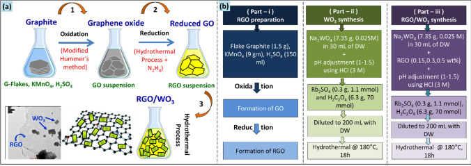
The chemicals used in a representative synthesis were: graphite flakes, potassium permanganate (KMnO4), sulfuric acid (H2SO4), sodium tungstate (Na2WO4), hydrochloric acid (HCl), oxalic acid (H2C2O4), and rubidium sulfate (Rb2SO4). All the reactants were AR-grade class, obtained from Sigma Aldrich, and used as received. For the entire synthesis process, double distilled water (DW) was used. Scheme 1 provides a condensed schematic that describes the whole synthetic protocol (Scheme 1a), along with the planning of the relevant sample classes described in this article (Scheme 1b).
Scheme 1.
(a) Complete synthesis steps of RGO/WO3 nanocomposites, (b) Set of samples’ flow chart.
RGO preparation
RGO was synthesized in the first part using the modified Hummer method13, where the graphite flakes were chemically oxidized. As the oxidation of graphite is exothermic process, the reaction individuals (Graphite flakes, KMnO4, H2SO4) were cooled down (~ 10–15 °C) prior to actual reaction. To be at better side (and needlessly), the Teflon liner which the reaction was planned, was also cool down to the same temperature of the reactants. The refrigerated graphite (1.5 g) and KMnO4 (9 gm) were transferred into the Teflon lined vessel, followed by the addition of H2SO4 (150 ml). As soon as the H2SO4 was added, the oxidation of graphite started. The Teflon liner was covered with its airtight lid and inserted in the stainless steel autoclave. The autoclave was then fixed firmly and placed in the refrigerator at 0–4 °C for 1.5 h. This step of cooling the reaction mixer is favored to obtain the uniform and minimal/thin layers of GO nanosheets. Finally, the reduction process for obtaining the RGO, autoclave was heated to 100 °C for 1.5 h. The obtained black slurry was treated with hydrazine hydrate solution (30% N2H4) upon constant stirring, till the color of the slurry turns into golden yellow. The mixture was then washed with HCl (2 M), followed by double distilled water, till the suspension pH becomes 7. The suspension was eventually filtered and dried at 80 °C to generate dark brown/black reduced graphene oxide.
RGO/WO3 synthesis
In the second part, desired amount of GO was dispersed in 10 mL ethanol/water mixture by ultrasonicating the suspension for 2 min, only. The extended ultrasonication is not favored to prevent the nanosheets from tearing off. As obtained GO suspension was added to separately prepared aqueous solution of sodium tungstate (7.35 gm, 0.025 M) under constant stirring. The solution was acidified to pH 1–1.5 using HCl (3 M), to obtain the lemon yellow colored precipitate. Complexing surfactants Rb2SO4 (0.3 g, 1.1 mmol) and H2C2O4 (6.3 g, 70 mmol) were then added to the mixture and diluted to 200 mL using distilled water. A translucent, homogeneous and stable GO/WO3 sol was obtained. This solution was transferred to 250 mL Teflon contained autoclave, sealed, and maintained at 180 °C for 18 h. Autoclave was allowed to cool down naturally, and the product was filtered, washed, and dried at room temperature (27 °C) followed by annealing at 400 °C in air for 2 h. For the control experiment (pristine WO3), the aforementioned procedure was followed without an addition of GO. The samples were labelled as “G0”- for pristine WO3, and “G1, G2, G3”- for 0.15, 0.3 and 0.5 wt% of GO loaded WO3.
Measurements
The crystal structures of as-synthesized materials were characterized by X-rays diffractions (XRD) with the incident of radiation (λ = 1.5406 Å, scan rate = 0.01°/s, scan range = 10–80°) at Dmax 2550 V X-ray (Rigaku, Tokyo, Japan) diffractometer. The field emission scanning electron microscopy (FESEM, Bruker XFlash 6130) and transmission electron microscopy (TEM, FEI Techni, G2, 300 kV) were used to investigate the microstructural and grain size evolution of the developed hierarchical assembly. In order to revalidate the crystal structure obtained from XRD, high-resolution electron microscope (HRTEM) and selective area electron diffraction (SAED) images were used. The specific surface area was determined by the Quantachrome Instruments ST-2000 surface and pore size analyser. The distribution of the pore size was calculated using the BJH method from the adsorption/desorption isotherms.
Sensor fabrication and test method
The study of gas response was performed using an indigenous 1 L capacity gas sensor chamber (presented in our earlier reports), built commercially14. The thick sensor films were produced with screen printing technique. For this purpose, the active material paste was formulated into the temporary binding agents (ethyl cellulose and butyl carbitol acetate). In the paste formulation, the proportion from inorganic to organic was held at 70:30 vol%. The paste was then moved to the mesh for screen printing and squeegeed on the pre-cleaned alumina substrates. These thick films were dried at room temperature, followed by sintering at 400 °C for 1 h, to eliminate the binder. Electrode pattern was prepared by using silver paste for the electrical measurements.
The sensor temperature can be controlled up to 400 °C with ± 2 °C precision. The as-prepared sensor thick film was fixed tightly to the two-probe sample holder. This assembly goes into the tubular furnace with the coaxially fitted glass chamber. At different operating temperatures, the sensor thick films were analyzed for various test gases. The sensor response (S) was specified in Ra/Rg, where Ra and Rg are the sensor resistance values, which are determined in both the air and the gas atmosphere of the test. The various test gases like acetone, ammonia, ethanol, trimethylamine, xylene, propanol, and diethanolamine and hydrogen sulphide gas, were analysed.
Photocatalytic activity test
Rhodamine-B dye degradation was evaluated for photocatalytic activity of RGO/WO3 nanostructures. A photocatalyst powder (0.3 g) was added to Rhodamine B aqueous solution (5 mg/L, 100 mL) at room temperature to prepare the reaction suspension. The suspension was constantly mixed for 60 min in the dark before putting it under natural sunlight. The solution was finally placed in a magnetically stirred beaker and irradiated under the natural sunlight. On a digital lux meter, the average intensity of natural sunlight was measured and 8.95 × 10⁴ lx was found. Irradiated sample aliquots at a specific time interval were reserved, Rhodamine B degradation was determined using UV–Vis analysis (Cary UV-60 Spectrophotometer, Agilent Technologies). Following a degradation of the dye, the maximum absorption band of Rh B at 553 nm gets changed. The degradation efficiencies of the dyes were estimated by the equation:
| 1 |
where Ci and Cf are the dye concentration in solution before and after irradiation. Furthermore, the other parameters like Rhodamine B concentration, the irradiation time effect and the degradation efficiency, were studied.
Results and discussion
The crystallinity and phase formation of the developed material was characterized by XRD technique as shown in Fig. 1.
Figure 1.
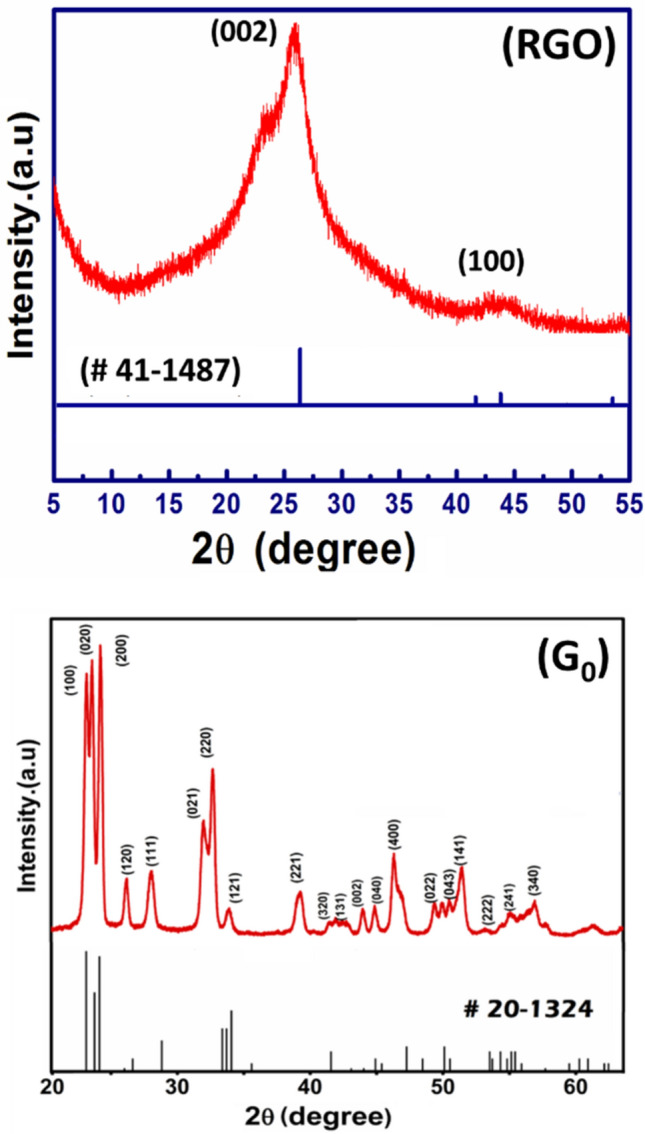
XRD signatures of self-developed (RGO), and pristine WO3 (G0).
In the XRD signature of as-developed RGO, the concentrated peak at ~ 26° of 2θ clearly demonstrates the self-made RGO is in well agreement to those obtained from commercial sources. The primary diffraction peak at 25.9° and secondary peak at 43.8° corresponds to (002) and (100) plane of graphite, respectively (JCPDS-Card No. 41-1487). This shows that the desired RGO preparation by graphite oxidation is very promising. The XRD spectrum of the developed WO3 (sample G0) authorizes the orthorhombic crystal structure. Though all RGO/WO3 samples (G1–G3) show the same crystal structure (orthorhombic), their XRD comparison is highlighted in the supplementary section for the more clarity (see SI-I). However, the crystallite size and lattice parameters are tabulated over here in Table 1. The smaller crystallite sizes (10.8–10.9 nm), are undoubtly giving the impression of a possible applicant for improved gas sensing and photocatalytical property, since the smaller crystallite size provides a greater surface area, which increases the likelihood of adsorption/desorption or interaction15. From the Table 1 (and as per the expectation), the developed RGO/WO3 nanocomposites show no influence of RGO loading in WO3 matrix. The XRD comparison graphs (see SI-I) also revalidates the no profound influence of RGO (0.15 to 0.5 wt%) on the crystal structure and plane orientations. In addition, comparatively less loading amount as well as low diffraction intensity of graphene, shows no distinguished peaks with respect to WO3 characteristic peaks16. The homogeneous distribution and presence of RGO in WO3 structure (sample G2) are illustrated in the elemental mapping and EDS spectrum (Fig. 2). Further, the EDX spectra of RGO confirm presence of carbon element with prominent high intensity peak of carbon. The EDX spectra of sample G2 illustrates the strong signals of elementals W, O with C indicating the phase purity of synthesized material. Elemental distribution in the EDS spectrum designates the compositional ratio of W:O is almost 1:3, which is in line with the stoichiometric percentage of WO3. The elemental mapping of sample G2 showcase the uniformity in the distribution of graphene. The EDAX analysis of sample G0-G4 indicates the presence of W, O and C are in the atomic proportions with the initial precursor amounts taken (See SI-II, Table S1). In Fig. 2, the atomic ratios of the elements of RGO and sample G2 are shown in percentage (see inset table). The EDS graph (left side) showcase the respective elements of the sample in accordance with their amounts. For more clarity, the EDS spectrum of samples G0, G1, and G3 are highlighted in the supplementary section (SI-III).
Table 1.
Sample id, crystallite size and the lattice parameters of the developed RGO/WO3.
| Sample id | Crystallite size (nm) | Lattice parameters (Å) |
|---|---|---|
| G0 | 10.8 | a = 3.86, b = 7.54, c = 7.32 |
| G1 | 10.8 | a = 3.86, b = 7.54, c = 7.32 |
| G2 | 10.9 | a = 3.86, b = 7.54, c = 7.32 |
| G3 | 10.9 | a = 3.86, b = 7.54, c = 7.32 |
Figure 2.
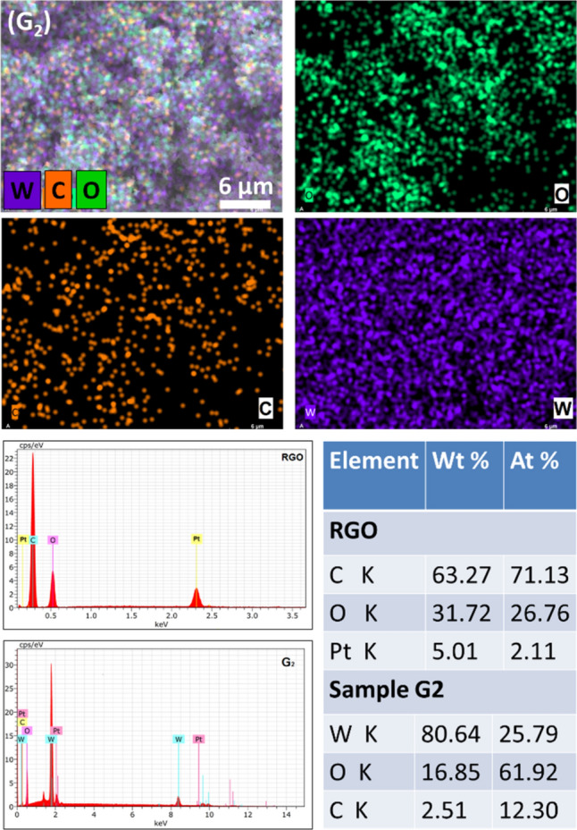
Elemental mapping of sample G2, and EDX spectra of RGO and G2 sample with analysis table.
The hierarchical architectures of RGO/WO3, developed by facile hydrothermal technique, are highlighted in Figs. 3 and 4. The FESEM images of pristine and RGO/WO3 materials (Fig. 3) shows marigold microstructure, having composed of numerous nanoplates (see magnified FESEM images) got arranged in such a way that the stable morphology appears to be a marigold flower. These nanoplates are having the dimensions ~ 90–160 nm in length, ~ 85–95 nm in width, with the third dimension ~ 20–30 nm thick. The nanoplates are well resolved in the TEM analysis (Fig. 4). Speaking about RGOs morphology, its FESEM clearly shows the layered structure of carbon. The natural wrinkles in the carbon layers are seen due to their Van der Waals interactions, where the agglomeration is understandable at elevated temperature. Upon incorporation of these wrinkled layers (i.e. RGO) in the WO3 matrix, a slight change in the morphology is observed. Though, the parent microflower structure is preserved, the gradual change in the diameter of the microflower with disturbed compactness is seen. With increasing RGO content, the ability of forming bigger rounds is ceased, which is in the fitness of the natural behavior. Graphene sheets might act as separators between two WO3 moieties. The subsequent loosening of nanoplates is highlighted by different FE-SEM image which is shown in supplementary information (SI-IV). The unique and controlled morphologies observed in the present RGO/WO3 samples are likely to make promising materials as gas sensors and photocatalysts.
Figure 3.
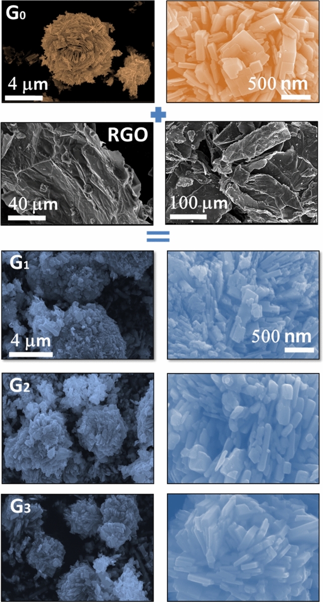
FESEM images of pristine (G0) and RGO/WO3 (G1–G3), samples along with self-made RGO.
Figure 4.
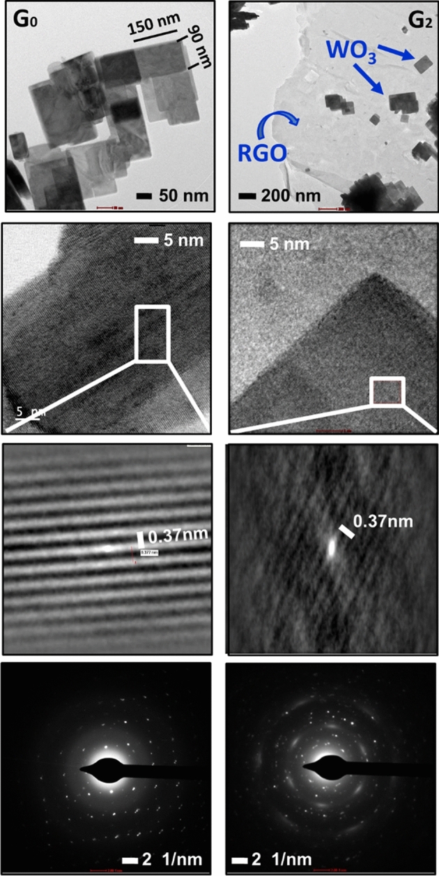
TEM images of low and high magnification with HRTEM and SAED pattern of pristine and 0.3% RGO/WO3 samples.
The microstructure of pristine WO3 (sample G0) and RGO/WO3 nanocomposite with 0.3 wt% of graphene (sample G2) are analyzed under TEM (Fig. 4). As discussed in the FE-SEM section, these nanoplates have the dimensions of length ~ 90–160 nm, and width ~ 85–95 nm. They are highly uniform, with high aspect ratio (Fig. 4). The nanoplates shape and uniformity remain undisturbed by the incorporation of RGO in the WO3 matrix. These nanoplates got well-dispersed over the thin graphene sheet, which is clearly visualized in the TEM image. These results are in well agreement with the elemental mapping studies under EDS analyses. HRTEM images show the lattice fringes spacing to be around 0.37 nm, equivalent to an o-WO3 plane (1 0 0). These nanoplates grown along a-direction of the lattice plane. The SAED pattern shows the transformation of single crystalline nature to polycrystalline, as RGO was incorporated in the WO3 matrix.
Let us now discuss the growth mechanism of RGO/WO3 nanocomposites. At the outset, the H2WO4 form on the RGO surface when an acid solution is added. H2WO4 is transformed into the WO3 crystal nucleus in the hydrothermal atmosphere, and promotes the nucleation of the WO3. The RGO sheets have baseline planes embellished by the groups of epoxy and hydroxyl, while groups of carbonyl and carboxy occur at borders15. All these groups act as anchor sites to support the building of RGO/WO3 nanoplates. Furthermore, hydrothermal reductions at high temperature and pressure can be seen as an effective way of re-establishing sp2 hybridized network17. At this supercritical temperature and pressure condition, the rupture of non-reactive oxygen comprising moieties occur18. As the amount of graphene increases, it implies a significant interaction between WO3 nuclei and graphene plate. This population density leads to the growth of crystal into nanoparticles. Additionally, graphene has brittle nature, and very delicate at elevated temperature. Thus, the formation of irregular nanoparticles is obvious. As a result, disturbed compactness of the RGO/WO3 microflower structure is observed in the present case, as the RGO was incorporated in the WO3.
To obtain the surface area and pore size distribution of as-developed RGO/WO3 nanomaterials, nitrogen multilayer adsorption/desorption (BET) measurements were performed (Fig. 5). The process encapsulates the calculation of external as well as pore areas to assess the overall specific surface area, which provides crucial knowledge in investigating the effects of surface porosity and particle size, in the present case of dual applications (gas sensor and photocatalysis).
Figure 5.
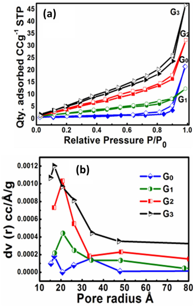
BET analysis curves (a) N2 absorption/desorption isotherms, and (b) Pore size distribution of samples G0–G3.
A hysteresis loop of isothermal adsorption–desorption of N2, ranges in the relative pressure (P/P0) of 0.1–0.9 for each sample. The obtained hysteresis loops are representative of type IV isotherm, with the form H3 and H4 loop-type. Type H3 loop represents loose groupings of plate-like particles, that form slit pores. This ultimately indicates that the sample G0 and G1 are composed of mesoporous microstructure. After increase in the amount of graphene the mesoporous structure is retained with H4 type of hysteresis loop, indicating a finite multilayer formation corresponding to complete filling of the capillaries and wide distribution of pore sizes. Table 2 shows Average pore radius (Å), Pore volume (cm3/g), and surface area (m2/g) of pristine and RGO incorporated WO3 samples.
Table 2.
Average pore radius, Pore volume and Surface area of pristine and RGO incorporated WO3 samples.
| Sample id | Avg. pore radius (Å) | Pore volume (cm3/g) | Surface area (m2/g) |
|---|---|---|---|
| G0 | 34.19 | 0.034 | 3.28 |
| G1 | 20.90 | 0.018 | 6.61 |
| G2 | 20.83 | 0.047 | 13.86 |
| G3 | 20.77 | 0.069 | 20.04 |
Gas sensing studies
From the physico-chemical analyses, the developed RGO/WO3 nanocomposites with hierarchical morphology could be very promising material for gas sensing response due to their large effective surface area and great surface activity. This unique and hierarchical microstructure encourages us to further investigate gas sensing performance of developed RGO/WO3 nanomaterial. They found very efficient towards various reducing gases such as Propanol, Xylene, Acetone, Diethanolamine, Trimethylamine, Ethanol, Ammonia, and Hydrogen sulphide. This proficiency was explored systematically and illustrated in Fig. 6a. Amongst the response values (Ra/Rg) of all the test gases, sample G2 showed Ra/Rg = 3.11 response towards H2S at mere concentration of 1 ppm, at 300 °C operating temperature. Compared to other test gases, the obtained response is more than double, even at lower concentrations, at the same operating temperature. The investigations were, therefore, focused towards H2S gas sensing application.
Figure 6.
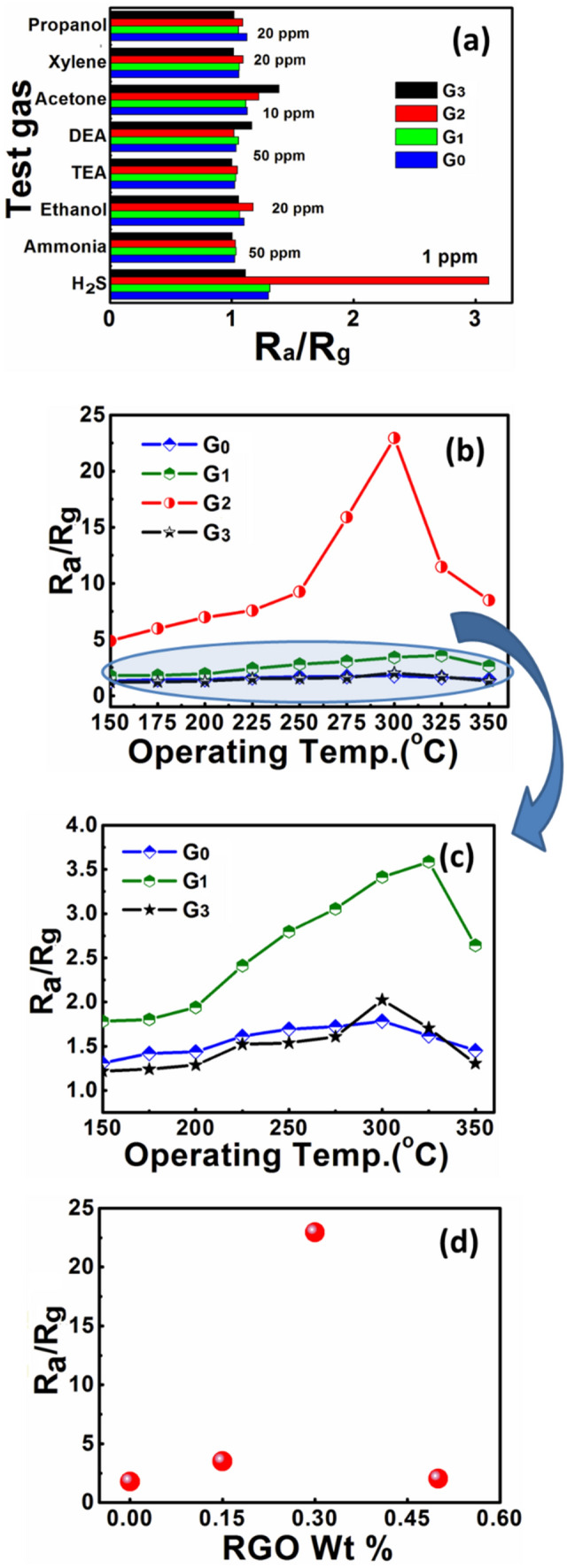
(a) Comparative analysis sensor response towards various test gases at 300 °C, (b and c) Sensor response as a function of operating temperature for pristine WO3 and RGO/WO3 samples towards 100 ppm H2S, respectively, (d) Effect of RGO loading on H2S sensing.
In the optimum operating temperature studies of pristine and RGO incorporated WO3, all the sensors exhibited a distinct hump at an optimum operating temperature (see Fig. 6b). The hump is clearly visualized for sensor G2 in comparison to sensor G0, G1, and G3, due to large difference in the response magnitude. To explore it in more detailed manner, the graph for sensor G0, G1, and G3 is extrapolated in Fig. 6c, where the sensors shows -(i) the increased response, (ii) attain a peak value, and (iii) eventually drops with increasing operating temperature. The enhancement in the gas response of pristine WO3 after incorporating the graphene sheets, is due to the fact that -(i) increased conducting channels, and (ii) increased surface area.
In case of sensor G2, the fourfold increment in the surface area, led to optimal incorporation of RGO in the WO3 matrix. The loosely organized porous structure offers plentiful passages for effective and quick diffusion of H2S gas1. Furthermore, for the improved gas sensing competence, the WO3 board like morphology is useful in creating a bound film of RGO and WO35. From the aforementioned studies, it is very clear that, though the higher dose of RGO incorporation overshoots the surface area, the proper amount of RGO incorporation plays a vital role in sensing H2S or any other test gas. Figure 6d demonstrates the H2S response values of the sensors at various RGO dosing; where remarkable improvement in the response is observed for 0.3 wt% of RGO in WO3. The Ra/Rg value shoot-up to 22.9 from 1.8, for 100 ppm H2S at 300○C of operating temperature. A significant influence on the performances of sensors is observed after uniform addition of WO3 to RGO planes. The WO3/RGO active surfaces have also the profound influence on performance of the chemical sensors. The response got decreased to 2.02 after further increase in the RGO loading to 0.5 wt%. It is due to the fact that large amount of RGO increases number of holes, which indicates the p-type behavior of the sensing element.
Figure 7a depicts the sensor G2 response with respect to H2S concentration at the optimum operating temperature (300 °C). At low concentrations of H2S (1 to 10 ppm), the sensor displayed a strong linear relation between the response and gas concentration. However, the active surface leads to saturation that causes a saturated response from 100 ppm of H2S concentration. The low population density of target gas implies to low surface reactions, and thereby the lower response. However, the surface reaction increases due to a large surface cover with increased gas concentration. The response saturates above certain concentration thresholds, and the active surface gets ceased for possible interaction of gas with the sensing material19. The sensor G0, G1, and G3 response as a function of function of H2S concentration at the optimum operating temperature (300 °C) is highlighted in the supplementary section (SI-V).
Figure 7.
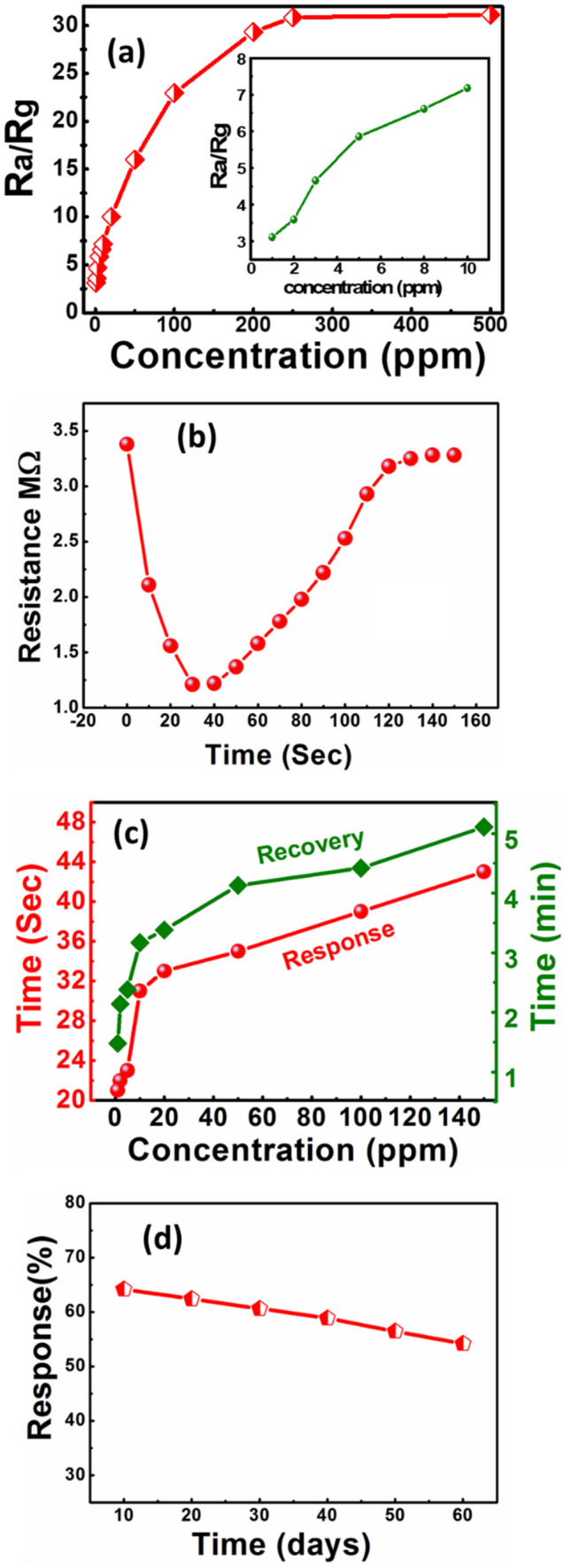
Response characteristics of sensor G2 with respect to -(a) the concentration of H2S at 300○C, -(b) Transient for 1 ppm H2S at 300○C, (c) Response/Recovery over H2S concentration, and (d) stability.
The transient reaction of sensor G2 in Fig. 7b shows the distinct valley in the transient response, which points out that the developed material is a good candidate for detecting H2S, as the peak response occurs relatively earlier (23 s) and it has faster recovery (75 s) time for 1 ppb of H2S. In Fig. 7c, the data indicates the specific gas concentration and the response/recovery time in such sensor. The sensors response gets quicker if an H2S concentrations get higher which is according to natural pattern.
The stability and reproducibility studies of the G2 sensor are depicted in Fig. 7d. Testing of the sensor stability and reproducibility were carried out at optimized operating temperature (300 °C) with measuring the sensor response to 1 ppm H2S concentration. After every ten days of initial measurements, gas sensing measurements are repeated over a duration of two months. It is observed that the sensor response is almost 85% of its initial measurement.
Improved H2S sensing mechanism of RGO/WO3
The surface adsorption and reaction models are described in Scheme 2, to illustrate the H2S sensing process. Tungsten trioxide is well known for resistive-type gas sensing material. The gas sensing response of WO3, is prominently influenced by the chemisorbed oxygen, type of the test gas, and the interaction between them. When the sensor temperature is around 300 °C, the dominant chemisorbed oxygen ion is O−20. As shown in the Scheme 2A, in the absence of H2S gas, the molecules of oxygen adsorbed onto the surface of WO3 nanoplates converted into O2−, O− or O2− by catching the electrons from the CB of WO3. Eventually, the electron depletion region is formed, which has comparatively larger resistance state21. When H2S gas is flowed over the sensor, the chemisorbed oxygen reacts with H2S molecules, thereby releasing the electrons back to CB of WO3 (see Eq. 2). This forms the lower resistance state of the sensor.
| 2 |
Scheme 2.
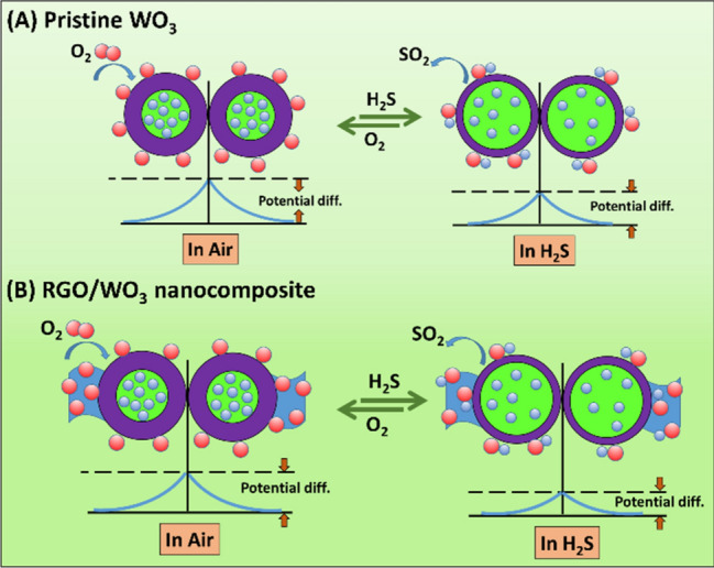
Schematic of (A) Pristine WO3 and (B) RGO/WO3 nanocomposite sensor system.
As the working temperature rises up, even better response can be realized, due to more number of active oxygen molecules. This process can be preserved to a certain degree, then-after the gas adsorption becomes subsequently difficult and gas molecules starts to desorb greatly. This eventually, reduce the response performs of the sensor22.
There are many reasons for crediting the improved H2S sensing response by a 0.3 wt% RGO/WO3 nano-composite sensor (sample G2). First of all, the hierarchical mesoporous nanostructure enabled the better flow of H2S gas into the sensor through variety of channels, resulting in the reaction phase in a fine touch between H2S and internal WO3 grains. Secondly, the transfer of charge carriers get facilitated by RGO with excellent electrical properties. And thirdly, additional oxygen molecules on the surfaces of sensors from the WO3 conduction bands, and chemisorbed oxygen concentrations rises the primarily O− as seen in Scheme 2b. More electrons get emitted into the sensing medium due to increasing the O− concentration. This results in a higher H2S response in the composite system, than a pure WO3. WO3 is, moreover, a common semiconductor of n-type; and RGO is a semiconductor of p-type. The movement of majority charge carriers (holes and electrons) combines together, and results in the decrease in the effective carriers’ concentration, followed by vacant space charge region, called as depletion layer. This depletion layer is formed near the interface, which leads to increase the Ra value (resistance in air). Therefore, the response gets increased23. In the following, the comparison Table 3 is made to describe the present work status with the state-of-art literature.
Table 3.
Comparison present work status with the state-of-art literature.
| Material | H2S conc (ppm) | Working temp (°C) | Response (Ra/Rg) | Refs. |
|---|---|---|---|---|
| CuO-functionalized WO3 nanowires | 100 | 300 | 6.72 | 24 |
| WO3 nanowires | 100 | 300 | 1.84 | 24 |
| Pd-NPs/Pd-embedded WO3 nanofibers | 1 | 350 | 1.36 | 25 |
| 0.01 wt% Au | 2 | 300 | 7.5 | 26 |
| Hexagonal (h-) WO3 | 10 | 200 | ~ 7 × 10⁻⁹ | 27 |
| Ag-βVO3 nanowires | 50 | 250 | 1.04 | 28 |
| RGO/WO3 | 1 | 300 | 3.11 | This work |
Photocatalytic activity study
Inexhaustibly available solar energy offers promising solution to solve the environmental problems30–36. Photocatalysis is one of the approaches to deal with the contaminants that are present in the water37–42. This novel approach motivated us to practice the as-developed RGO/WO3 nanocomposites for degradation of dye molecules in the water, under the natural sunlight in ambient conditions. For this purpose, Rhodamine B aqueous solution is prepared, to treat with the developed catalyst RGO/WO3. The resultant suspension is kept in the sunlight.
Figure 8 describes the dynamic variations of Rhodamine-B absorption, in the presence of catalysts G0, G1, G2 and G3. It shows that with the increased irradiation time, the characteristic peak of absorption for RGO/WO3 aliquots was gradually reduced. The peak reduction is not significant in case of pristine WO3. This clearly shows that RGO has a major impact in improving the surface area (seen in the BET analysis), thereby, the photocatalytic dye degradation process. After 3 h of irradiation, for catalyst G1 the blue shift of the absorption peak is very small (not more than 14 nm after 180 min, 539 nm). However, the optimized RGO incorporation in WO3 has a major role in enhancing the photocatalytic process. A larger hypsochromic peak shift of 24 nm after 180 min (510 nm) due to de-ethylation of RhB, is observed in sample G2. Catalyst G3 exhibited a significant peak shift after 210 min of irradiation (similar to pristine WO3). All in all, the solution's maximum absorbing range has gradually changed between 554 and 499 nm. RhB N-deethylation is the result of the gradual hypsochrome shifts of absorption during radioactivity29. This hypochromatic shift in λmax of RhB equals a gradual deethylation of RhB, giving N,N,N0-triethyl rhodamine (TER, 539 nm), N,N0-diethyllrhodamine (DER, 522 nm), N-ethyl-rhodamine (MER, 510 nm) and 498 nm rhodamine. The RhB molecule step by step loosens the ethyl groups to become stable products. Meanwhile, the dye solution is translated colourless from pink, suggesting that the porous RGO/WO3 products are good having photocatalytic activity.
Figure 8.

UV/Vis spectroscopic absorption of RhB aliquots in the presence of G0, G1 G2 and G3 catalysts.
Figure 9a and b show the photo-activeness (C/C0) and photo-degradation potency (η%) of pristine and RGO/WO3 catalysts under the natural sunlight for Rhodamine B dye molecules. The sample G2 (0.3 wt% RGO/WO3) shows the highest degradation efficacy (94%) for RhB over the pristine WO3 (61%). This is due to the fact that pristine WO3 has low propensity to utilize the natural sunlight for photocatalysis. In addition, it suffers through high degree of charge-recombination. The role played by RGO in enhancing WO3 photoactivity can be attributed for the purpose of enhancing the separation and transfer of charge carriers from semiconductors (Scheme 3). It increases WO3′s light harvest capacity and promotes efficient transfer and separation of electron–hole photogenerated pairs. However, if the RGO weight percentage ratio is increased to 0.5%, photoactivity declines which can be attributable to the effect of shielding43. In the state of the art, such an optimum synergic result was widely observed between graphene and semiconductor44–46.
Figure 9.
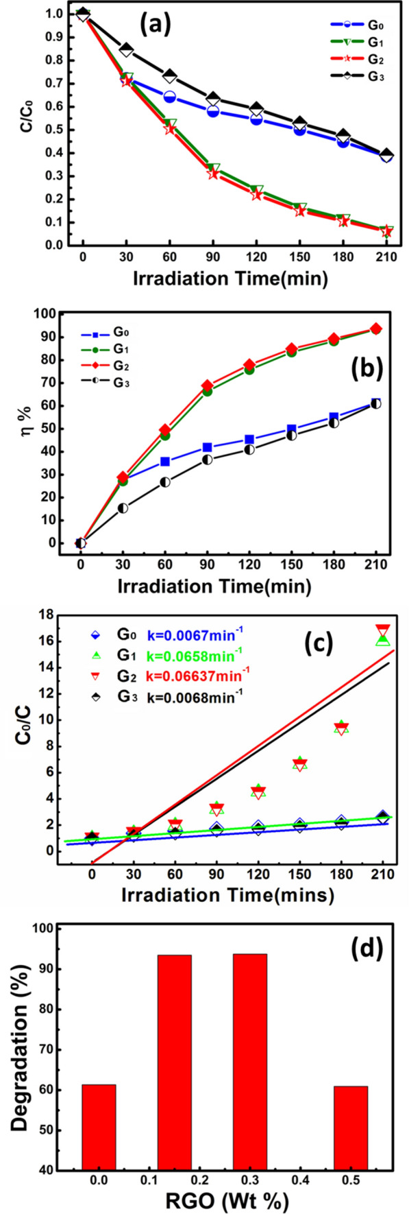
(a) Photo-activeness (C/C0), (b) Photo-degradation potency (η%) of pristine and RGO/WO3 catalysts under the natural sunlight for Rhodamine B dye molecules, (c) Photocatalytic degradation kinetics of developed catalysts, and (d) RGO incorporation effect over degradation after 210 min.
Scheme 3.
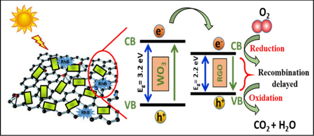
Schematic illustrating the photocatalytic activity of RGO/WO3 nanocomposite, under natural sunlight.
The curves for the entire sample sets are best fitted as shown in Fig. 9c, given the fact that dye degradation is indorsed to first order pseudo reaction with a simplified Langmuir–Hinshelwood model. The graphical evaluations of rate constants are increased from 0.0067 to 0.0664 min−1, which is nearly ten times more than pristine one. Figure 9d demonstrates the degradation efficiency pathway for RGO incorporation in weight percent. Pristine and 0.5 wt% RGO/WO3 exhibited lower degradation efficiency compared to 0.15% and 0.3% of RGO incorporation. The 0.3% of RGO have maximum hypsocromic shift followed by formation of Rhodamine from Rhodamine B with maximum degradation efficiency. The result can be correlated with the surface area of the photocatalyst. Herein, G2 with the higher surface area has provided more active sites for the reactant molecules. Large BET surface area with optimal RGO, holds strong adsorption ability to improve the photocatalytic activity. In the following, the comparison Table 4 is made to describe the present work status with the state-of-art literature.
Table 4.
Comparison of present work status with the state-of-art literature.
Conclusion
In conclusion, the pristine and RGO incorporated WO3 hierarchical marigold micro-flowers are developed via simple hydrothermal route. The self-made RGO using modified Hummer’s method has dramatically improved the surface area of the parent metal oxide, by the factor of 7 (from 3.2 to 20.0 m2/g). XRD analysis confirmed the orthorhombic crystal structure of as developed RGO/WO3 nanocomposites. The morphological and EDS elemental mapping showcased the uniform spreading of WO3 on the graphene layer. The prime motivation of increasing the surface area and surface active sites was realized through BET analysis, which gave the hint to use the developed nanocomposites of multidisciplinary applications. The excellent ability of gas sensor towards H2S gas (Ra/Rg = 3.1 per ppm) and natural sunlight-driven photocatalysis of rhodamine B (94% in 210 min) were induced in the pristine WO3 by incorporating 0.3 wt% of RGO. Sample G1 and G2 almost have the almost same photocatalytic activity but different sensitivity. The gas response amongst the same metal oxide but with different loading of RGO, differs due to spillover mechanism. The work showcase, the designed approach of developing RGO/WO3 nanocomposite has high potential in multidisciplinary applications such as gas sensor and photocatalysis.
Supplementary Information
Acknowledgements
The authors greatly acknowledge the CSIR, India, for financial support of this work (03(1389)/16/EMR-II). Dr. Digambar Nadargi acknowledges UGC Dr. D. S. Kothari PostDoctoral Fellowship Scheme, India for awarding PostDoctoral Fellowship and financial support of this work (No. F.4-2/2006(BSR)/PH/19-20/0013). This work was supported by “Human Resources Program in Energy Technology” of the Korea Institute of Energy Technology Evaluation and Planning (KETEP), granted financial resource from the Ministry of Trade, Industry & Energy, Republic of Korea. (No. 20204010600100). Dr. Thamraa Alshahrani extend their sincere appreciation to the Deanship of Scientific Research at Princess Nourah Bint Abdulrahman University through Fast-track Research Funding Program.
Author contributions
S.M, D. N. and S.S. planned and designed the experiments. M.T., I.M, V.R. and E.K. performed the experiments and calculations. T. A. S.M, D. N. C.P. and S.S. analyzed the data and interpreted the experimental results. All authors contributed equally to writing the manuscript.
Competing interests
The authors declare no competing interests.
Footnotes
Publisher's note
Springer Nature remains neutral with regard to jurisdictional claims in published maps and institutional affiliations.
These authors contributed equally: Swati S. Mehta and Digambar Y. Nadargi.
Contributor Information
Digambar Y. Nadargi, Email: digambar_nadargi@yahoo.co.in
Chinho Park, Email: chpark@ynu.ac.kr.
Sharad S. Suryavanshi, Email: sssuryavanshi@rediffmail.com
Supplementary Information
The online version contains supplementary material available at (10.1038/s41598-021-84416-1).
References
- 1.Mehta SS, Nadargi DY, Tamboli MS, Chaudhary LS, Patil PS, Mulla IS, Suryavanshi SS. Ru-loaded mesoporous WO3microflowers for dual applications: Enhanced H2S sensing and sunlight-driven photocatalysis. Dalton Trans. 2018;47:16840–16845. doi: 10.1039/C8DT03667E. [DOI] [PubMed] [Google Scholar]
- 2.Samal R, Chakraborty B, Saxena M, Late DJ, Rout CS. Facile production of mesoporous WO3-rGO hybrids for high-performance supercapacitor electrodes: an experimental and computational study. ACS Sustain. Chem. Eng. 2019;7(2):2350–2359. doi: 10.1021/acssuschemeng.8b05132. [DOI] [Google Scholar]
- 3.Li Y, Tanga Z, Zhang J, Zhang Z. Reduced graphene oxide three-dimensionally wrapped WO3 hierarchical nanostructures as high-performance solar photocatalytic materials. Appl. Catal. A Gen. 2016;522:90–100. doi: 10.1016/j.apcata.2016.04.034. [DOI] [Google Scholar]
- 4.Thummavichai K, Trimby L, Wang N, Wright CD, Xia Y, Zhu Y. Low temperature annealing improves the electrochromic and degradation behavior of tungsten oxide (WOx) thin films. J. Phys. Chem. C. 2017;121(37):20498–20506. doi: 10.1021/acs.jpcc.7b06300. [DOI] [Google Scholar]
- 5.Mehta SS, Nadargi DY, Tamboli MS, Patil VB, Mulla IS, Suryavanshi SS. Macroporous WO3: tunable morphology as a function of glycine concentration and its excellent acetone sensing performance. Ceram. Int. 2019;45(1):409–414. doi: 10.1016/j.ceramint.2018.09.181. [DOI] [Google Scholar]
- 6.Pathak R, Gurung A, Elbohy H, Chen K, Reza K, Bahrami B, Mabrouk S, Ghimire R, Hummel M, Gu Z, Wang X, Wu Y, Zhou Y, Qiao Q. Self-recovery in Li-metal hybrid lithium-ion battery via WO3 reduction. Nanoscale. 2018;10:15956–15966. doi: 10.1039/C8NR01507D. [DOI] [PubMed] [Google Scholar]
- 7.Li Y, Tang Z, Zhang J, Zhang Z. Reduced graphene oxide three-dimensionally wrapped WO3 hierarchical nanostructures as high-performance solar photocatalytic materials. Appl. Catal. A. 2016;522:90–100. doi: 10.1016/j.apcata.2016.04.034. [DOI] [Google Scholar]
- 8.Zhong M, Wen S, Ke Y, Liji P, Guihua Y. Doping engineering of conductive polymer hydrogels and their application in advanced sensor technologies. Chem. Sci. 2019;10:6232–6244. doi: 10.1039/C8SC05600E. [DOI] [PMC free article] [PubMed] [Google Scholar]
- 9.Nadargi D, Tamboli M, Patil S, Mulla I, Suryavanshi S. Development of Ag/ZnO nanorods and nanoplates at low hydrothermal temperature and time for acetone sensing application: an insight into spillover mechanism. SN Appl. Sci. 2019;1:1564. doi: 10.1007/s42452-019-1573-2. [DOI] [Google Scholar]
- 10.Atanu B, Nae-Eung L. Gas sensing with heterostructures based on two-dimensional nanostructured materials: a review. J. Mater. Chem. C. 2019;7:13367–13383. doi: 10.1039/C9TC04132J. [DOI] [Google Scholar]
- 11.Guo L, Hao YW, Li PL, Song JF, Yang R-Z, Fu X-Y, Xie SY, Zhao J, Zhang YL. Improved NO2 gas sensing properties of graphene oxide reduced by two-beam-laser interference. Sci. Rep. 2018;8:4918–4920. doi: 10.1038/s41598-018-23091-1. [DOI] [PMC free article] [PubMed] [Google Scholar]
- 12.Novoselov KS, Fal’ko VI, Colombo L, Gellert PR, Schwab MG, Kim K. A roadmap for grapheme. Nature. 2012;490:192–200. doi: 10.1038/nature11458. [DOI] [PubMed] [Google Scholar]
- 13.Huang M, Wu Y, Hu W. A facile synthesis ofreduced graphene oxide-wrapped WO3 nanowire composite and its enhanced electrochemical catalysis properties. Ceram. Int. 2014;40:7219–7225. doi: 10.1016/j.ceramint.2013.12.061. [DOI] [Google Scholar]
- 14.Nadargi D, Tamboli M, Patil S, Dateer R, Mulla I, Choi H, Suryavanshi S. Microwave-epoxide-assisted hydrothermal synthesis of the CuO/ZnO heterojunction: a highly versatile route to develop H2S gas sensors. ACS Omega. 2020;5(15):8587–8595. doi: 10.1021/acsomega.9b04475. [DOI] [PMC free article] [PubMed] [Google Scholar]
- 15.Zhang X, Lv XJ, Li YM, Wang Y, Li JH. P25-Graphene composite as a high performance photocatalyst. ACS Nano. 2010;4:380–386. doi: 10.1021/nn901221k. [DOI] [PubMed] [Google Scholar]
- 16.Shi J, Cheng Z, Gao L, Zhang Y, Xu J, Zhao H. Facile synthesis of reduced graphene oxide/hexagonal WO3 nanosheets composites with enhanced H2S sensing properties. Sensors Actuators B. 2016;230:736–745. doi: 10.1016/j.snb.2016.02.134. [DOI] [Google Scholar]
- 17.Nethravathi C, Rajamathi M. Chemically modified graphene sheets produced by the solvothermal reduction of colloidal dispersions of graphite oxide. Carbon. 2008;46:1994–1998. doi: 10.1016/j.carbon.2008.08.013. [DOI] [Google Scholar]
- 18.Lee J. Gas sensors using hierarchical and hollow oxide nanostructures: overview. Sensors Actuators B. 2009;140:319–336. doi: 10.1016/j.snb.2009.04.026. [DOI] [Google Scholar]
- 19.Mehta S, Nadargi D, Tamboli M, Mulla I, Suryavanshi S. CTAB assisted synthesis of tungsten oxide nanoplates as an efficient low temperature NOX sensor. J. Solid State Chem. 2018;258:256–263. doi: 10.1016/j.jssc.2017.10.026. [DOI] [Google Scholar]
- 20.Cheng B, Yang S, Liu T, Vazinishayan A. A novel nanowire assembly process for the fabrication of CO sensor. Sensors. 2018;18:1234. doi: 10.3390/s18041234. [DOI] [PMC free article] [PubMed] [Google Scholar]
- 21.Ma J, Mei L, Chen Y, Li Q, Wang T, Xu Z, Duan X, Zheng W. α-Fe2O3 nanochains: ammonium acetate-based ionothermal synthesis and ultrasensitive sensors for low-ppm-level H2S gas. Nanoscale. 2013;5:895–898. doi: 10.1039/C2NR33201A. [DOI] [PubMed] [Google Scholar]
- 22.Yin L, Chen D, Hu M, Shi H, Yang D, Fan B, Shao G, Zhang R, Shao G. Microwave-assisted growth of In2O3 nanoparticles on WO3 nanoplates to improve H2S-sensing performance. J. Mater. Chem. 2014;A2:18867–18874. doi: 10.1039/C4TA03426K. [DOI] [Google Scholar]
- 23.Xuan J, Zhao G, Sun M, Jia F, Wang X, Zhou T, Yin G, Liu B. Low-temperature operating ZnO-based NO2 sensors: a review. RSC Adv. 2020;10:39786–39807. doi: 10.1039/D0RA07328H. [DOI] [PMC free article] [PubMed] [Google Scholar]
- 24.Park S, Park S, Jung J, Hong T, Lee S, Kim H, Lee C. H2S gas sensing properties of CuO-functionalized WO3 nanowires. Ceram. Int. 2014;40:11051–11056. doi: 10.1016/j.ceramint.2014.03.120. [DOI] [Google Scholar]
- 25.Kim NH, Choi SJ, Yang DJ, Bae J, Park J, Kim ID. Highly sensitive and selective hydrogen sulfide and toluene sensors using Pd functionalized WO3 nanofibers for potential diagnosis of halitosis and lung cancer. Sensors Actuators B. 2014;193:574–581. doi: 10.1016/j.snb.2013.12.011. [DOI] [Google Scholar]
- 26.Lee I, Choi SJ, Park KM, Lee S, Choi S, Kim ID, Park C. The stability, sensitivity and response transients of ZnO SnO2 and WO3 sensors underacetone, toluene and H2S environments. Sensors Actuators B. 2014;197:300–307. doi: 10.1016/j.snb.2014.02.043. [DOI] [Google Scholar]
- 27.Szilágyi IM, Saukko S, Mizsei J, Tóth AL, Madarász J, Pokol G. Gas sensing selectivity of hexagonal and monoclinic WO3 to H2S. Solid State Sci. 2010;12:1857–1860. doi: 10.1016/j.solidstatesciences.2010.01.019. [DOI] [Google Scholar]
- 28.Mai L, Xu L, Gao Q, Han C, Hu B, Pi Y. Single AgVO3 nanowire H2S sensor. Nano Lett. 2010;10:2604–2608. doi: 10.1021/nl1013184. [DOI] [PubMed] [Google Scholar]
- 29.Watanabe T, Takizawa T, Honda K. Photocatalysis through excitation of adsorbates. Rhodamine B adsorbed to CdSJ. Phys. Chem. 1977;81:1845–1851. doi: 10.1021/j100534a012. [DOI] [Google Scholar]
- 30.Sharma B, Thakur S, Mamba G, Gupta RK, Gupta VK, Thakur VK. Titania modified gum tragacanth based hydrogel nanocomposite for water remediation. J. Environ. Chem. Eng. 2020;9:104608. doi: 10.1016/j.jece.2020.104608. [DOI] [Google Scholar]
- 31.Kar P, Jain P, Kumar V, Gupta RK. Interfacial engineering of Fe2O3@ BOC heterojunction for efficient detoxification of toxic metal and dye under visible light illumination. J. Environ. Chem. Eng. 2019;7:102843. doi: 10.1016/j.jece.2018.102843. [DOI] [Google Scholar]
- 32.Das G, Tripathi K, Kumar G, Paul S, Mehara S, Bhowmik S, Pakhira B, Sarkar S, Roy M, Kim TY. Nitrogen-doped fluorescent graphene nanosheets as visible-light-driven photocatalysts for dye degradation and selective sensing of ascorbic acid. New J. Chem. 2019;43:14575–14583. doi: 10.1039/C9NJ02344E. [DOI] [Google Scholar]
- 33.Jain P, Kumar A, Verma N, Gupta RK. In-situ synthesis of TiO2 nanoparticles in ACF: photocatalytic degradation under continuous flow. Sol. Energy. 2019;189:35–44. doi: 10.1016/j.solener.2019.07.042. [DOI] [Google Scholar]
- 34.Balasubramaniam B, Singh N, Kar P, Tyagi A, Prakash J, Gupta RK. Engineering of transition metal dichalcogenide-based 2D nanomaterials through doping for environmental applications. Mol. Syst. Des. Eng. 2019;4:804–827. doi: 10.1039/C8ME00116B. [DOI] [Google Scholar]
- 35.Singh N, Chakraborty R, Gupta RK. Mutton bone derived hydroxyapatite supported TiO2 nanoparticles for sustainable photocatalytic applications. J. Environ. Chem. Eng. 2018;6:459–467. doi: 10.1016/j.jece.2017.12.027. [DOI] [Google Scholar]
- 36.Singh N, Prakash J, Misra M, Sharma M, Gupta RK. Dual functional Ta-doped electrospun TiO2 nanofibers with enhanced photocatalysis and SERS detection for organic compounds. Appl. Mater. Interfaces. 2017;9:28495–28507. doi: 10.1021/acsami.7b07571. [DOI] [PubMed] [Google Scholar]
- 37.Das G, Bhatnagar A, Yli-Pirilä P, Tripathi KM, Kim RK. Sustainable nitrogen-doped functionalized graphene nanosheets for visible-light-induced photocatalytic water splitting. Chem. Commun. 2020;56:6953–6956. doi: 10.1039/D0CC01365J. [DOI] [PubMed] [Google Scholar]
- 38.Misra M, Singh N, Gupta RK. Enhanced visible-light-driven photocatalytic activity of Au@ Ag core–shell bimetallic naoparticles immobilized on electrospunTiO2 nanofibers for degradation of organic compounds. Catal. Sci. Technol. 2017;7:570–580. doi: 10.1039/C6CY02085B. [DOI] [Google Scholar]
- 39.Tyagi A, Tripathi KM, Singh N, Choudhary S, Gupta RK. Green synthesis of carbon quantum dots from lemon peel waste: applications in sensing and photocatalysis. RSC Adv. 2016;6:72423–72432. doi: 10.1039/C6RA10488F. [DOI] [Google Scholar]
- 40.Das G, Shim JP, Bhatnagar A, Tripathi KM, Kim TY. Biomass-derived carbon quantum dots for visible-light-induced photocatalysis and label-free detection of Fe(III) and ascorbic acid. Sci. Rep. 2019;9:15084. doi: 10.1038/s41598-019-49266-y. [DOI] [PMC free article] [PubMed] [Google Scholar]
- 41.Singh N, Mondal K, Misra M, Sharma A, Gupta RK. Quantum dot sensitized electrospun mesoporous titanium dioxide hollow nanofibers for photocatalytic applications. RSC Adv. 2016;6(53):48109–48119. doi: 10.1039/C6RA04305D. [DOI] [Google Scholar]
- 42.Misra M, Gupta RK, Paul AK, Singla M. Influence of gold core concentration on visible photocatalytic activity of gold–zinc sulfide core–shell nanoparticle. J. Power Sour. 2015;294:580–587. doi: 10.1016/j.jpowsour.2015.06.099. [DOI] [Google Scholar]
- 43.Zhang Y, Tang Z-R, Fu X, Xu Y-J. TiO2−graphene anocomposites for gas-phase photocatalytic degradation of volatile aromatic pollutant: Is TiO2−Graphene truly different from other TiO2−Carbon composite materials? ACS Nano. 2010;4:7303–7314. doi: 10.1021/nn1024219. [DOI] [PubMed] [Google Scholar]
- 44.Li Q, Guo B, Yu J, Ran J, Zhang B, Yan H-J, Gong JR. Highly efficient visible-light-driven photocatalytic hydrogen production of CdS-cluster-decorated graphene nanosheets. J. Am. Chem. Soc. 2011;133:10878–10884. doi: 10.1021/ja2025454. [DOI] [PubMed] [Google Scholar]
- 45.Zhang Y, Tang Z-R, Fu X, Xu Y-J. Engineering the unique 2D mat of graphene to achieve graphene-TiO2 nanocomposite for photocatalytic selective transformation: what advantage does graphene have over its forebear carbon nanotube? ACS Nano. 2011;5:7426–7435. doi: 10.1021/nn202519j. [DOI] [PubMed] [Google Scholar]
- 46.Zhang N, Yang M-Q, Tang Z-R, Xu Y-J. Toward improving the graphene-semiconductor composite photoactivity via the addition of metal ions as generic interfacial mediator. ACS Nano. 2014;8:623–633. doi: 10.1021/nn405242t. [DOI] [PubMed] [Google Scholar]
- 47.Bazarjani M, Hojamberdiev M, Morita K, Zhu G, Cherkashinin G, Fasel C, Herrmann T, Breitzke H, Gurlo A, Riedel R. Visible light photocatalysis with c-WO3−x/WO3×H2O nanoheterostructures in situ formed in mesoporous polycarbosilane-siloxane polymer. J. Am. Chem. Soc. 2013;135(11):4467–4475. doi: 10.1021/ja3126678. [DOI] [PubMed] [Google Scholar]
- 48.Katsumata H, Oda Y, Kaneco S, Suzuki T. Photocatalytic activity of Ag/CuO/WO3 under visible light irradiation. RSC Adv. 2013;3:5028–5035. doi: 10.1039/c3ra23322g. [DOI] [Google Scholar]
- 49.Lia N, Tenga H, Zhanga L, Zhou J, Liu M. Synthesis of Mo-doped WO3nanosheets with enhanced visiblelight-driven photocatalytic properties. RSC Adv. 2015;5:95394–95400. doi: 10.1039/C5RA17098B. [DOI] [Google Scholar]
Associated Data
This section collects any data citations, data availability statements, or supplementary materials included in this article.


