Abstract
An exciting and novel science mission concept called Seismic and Atmospheric Exploration of Venus (SAEVe) has been developed which uses high-temperature electronics to enable a three-order magnitude increase in expected surface life (120 Earth days) over what has been achieved to date. This enables study of long-term, variable phenomena such as the seismicity of Venus and near surface weather, near surface energy balance, and atmospheric chemical composition. SAEVe also serves as a critical pathfinder for more sophisticated landers in the future. For example, first order seismic measurements by SAEVe will allow future missions to deliver better seismometers and systems to support the yet unknown frequency and magnitude of Venus events. SAEVe is focused on science that can be realized with low data volume instruments and will most benefit from temporal operations. The entire mission architecture and operations maximize science while minimizing energy usage and physical size and mass. The entire SAEVe system including its protective entry system is estimated to be around 45 kg and approximately 0.6 m diameter. These features allow SAEVe to be relatively cost effective and be easily integrated onto a Venus orbiter mission. The technologies needed to implement SAEVe are currently in development by several funded activities. Component and system level work is ongoing under NASA’s Long Lived Insitu Solar System Explorer (LLISSE) project and the HOTTech program.
. LLISSE, is a NASA project to develop a small Venus lander that will operate on the surface of Venus for 60 days and measure variations in meteorology, radiance, and atmospheric chemistry. LLISSE is developing a full-function engineering model of a Venus lander that contains essentially all the core capabilities of SAEVe thus greatly reducing the technology risk to SAEVe.
The SAEVe long duration Venus lander promises exciting new science and is an ideal complimentary element to many future Venus orbiter missions being proposed or planned today.
Keywords: Venus, Lander, Long-duration, Seismology, Meteorology, SAEVe
1. Introduction
A mission concept has been developed to address long standing science data needs related to Venus, and specifically at its surface. The mission concept, called Seismic and Atmospheric Exploration of Venus (SAEVe) is to deliver two landers to the surface of Venus, and have them return high value science for 120 days, which is over three orders magnitude longer than anything previously achieved (Williams, 2019). The science focus of SAEVe is seismometry and meteorology, long standing gaps in our data of Venus and measurements that are enabled only by long duration operations. The remarkable operating life of SAEVe is enabled by three key elements, 1) high temperature electronics and systems that operate without cooling at Venus surface conditions, 2) use of simple instrumentation and supporting avionics which can accomplish science goals with low volume of data, and 3) minimizing energy utilization through a novel operations approach.
The lander payload of the SAEVe mission concept is supported by a unique and innovative platform designed to operate at Venus surface conditions where temperatures are 460 °C, pressure is over 90 bar, and reactive atmospheric chemistry is primarily composed of supercritical CO2 with contains sulphur species and other reactive elements. Delivery to Venus is assumed to be by a Venus mission which includes an orbiter that serves as a data relay. The current SAEVe mission concept architecture focuses solely on the entry, descent and landed elements and assumes a nominal 24 h elliptical orbit for the orbiter (see Section 5.2).
We present an overview of the development of the SAEVe descent and landed mission concept, beginning with a review of the science objectives and traceability to overarching science goals defined by the Planetary Decadal survey (Visions and Voyages for Planetary Science in the Decade, 2011), with specific measurements identified by the SAEVe science team. This is followed by discussion of the prioritized measurements and the instruments that can capture those measurements. We provide details of the entry and landing system concepts for the SAEVe mission. We also provide an assessment of the state of the art for technologies relevant to the SAEVe payload, entry, descent and landed elements, relative to readiness of each element. Finally, we provide a summary of ongoing funded work, and expected costs based on both internal and independent estimates. The orbiter architecture is not included in these studies, beyond costs for integration of the SAEVe delivery vessel to the orbiter vessel.
2. Science objectives and traceability
Due to its long life, the SAEVe mission concept is able to make two measurements that have not yet been made for Venus, and cannot be made with a short-lived (hours) lander: measurement of the seismicity of the planet and the composition and dynamics of the lower atmosphere over time. These measurements directly address some of the fundamental goals outlined in the National Research Council’s Planetary Decadal Survey (for 2013–2022) (Visions and Voyages for Planetary Science in the Decade, 2011), namely to “Understand the origin and diversity of the terrestrial planets,” and “Understand the processes that control climate on Earth-like planets”. SAEVe objectives also trace to specific scientific goals and objectives identified by the Venus Exploration Analysis Group (VEXAG) in their Goals, Objectives and Investigations Document, for example: III.A.Geologic Activity and III.A.Crust (VEXAF, Goals, Objectives and Investigations, 2019). SAEVe focuses on unanswered questions in three areas, 1) crust and interior, 2) atmosphere, and 3) surface processes.
2.1. Crust and interior questions targeted
Key open crust/interior questions that SAEVe will address include: How thick is the Venus crust and lithosphere? What is the composition of its crust? Is the heat loss from the interior by conduction through the crust, through volcanism or tectonism? Is there now, or has there ever been plate tectonics? There is mounting evidence for current volcanism (Smrekar et al., 2010; Shalygin et al., 2015), but its frequency, scale, and magnitude are not known. Magellan data reveal signs of tectonic activity such as extensional fractures and wrinkle ridges and the presence of highlands. These features are indicative of a convecting mantle, yet the current level of tectonism is unknown. The Planetary Decadal Survey (Visions and Voyages for Planetary Science in the Decade, 2011) question of “What are the major heat loss mechanisms associated dynamics of the cores and mantles?” is an example of an interior question that will be targeted by SAEVe.
2.2. Atmosphere questions targeted
Investigation of atmospheric dynamics and chemistry at the surface addresses the Planetary Decadal Survey (Visions and Voyages for Planetary Science in the Decade, 2011) questions of: “Determine how solar energy drives atmospheric circulation, cloud formation and chemical cycles that define the current climate on the terrestrial planets,” and “What are the key processes, reaction and chemical cycles controlling the chemistry of the middle, upper and lower atmosphere of Venus?”
One of the major mysteries about Venus is its rotation, both its direction and rate. The atmosphere is expected to influence the rotation rate on the short and long term through the exchange of momentum with the surface which changes the instantaneous rotation rate (Navarro et al., 2018). SAEVe will make regular pressure and temperature measurements to inform us about near surface heat fluxes due to local circulations such as slope or katabatic winds. While Venera 9,10 landers measured the wind speed with cup anemometers (Avduevskii et al., 1976) and Venera 13,14 with acoustic anemometers (Ksanfomality et al., 1982), SAEVet will provide the first temporal data related to the possible momentum exchange between the atmosphere and the surface.
Surface rocks are a major sink for atmospheric species, yet we have only thermodynamic predictions for the species, style and kinetics of these reactions because of limited direct measurements of atmospheric and surface chemistry. To address this problem, SAEVe includes a range of chemical sensors (SOx, H2O, OCS, HCl, HF, NO, O2 and HCN) that will provide new information about surface-atmosphere exchange. Variations in atmospheric chemistry may indicate transient inputs, such as volcanic gases.
2.3. Surface process questions targeted
Venera lander images reveal Venus surfaces dominated by layered rocks and mobile sediment, but the origin of these materials is still open (e.g., Garvin et al., 1977). Major unresolved questions include: what is the distribution and particle sizes at the landing sites? Are salts and cements present on the surface that might indicate surface-atmosphere interactions? Are there any structures (e.g., faults) observable in the scene that may correlate with larger scale deformation? Are there landforms in the scene (e.g., dunes) that might indicate presence and transport of sediments? Investigation of the surface of Venus can address one of the fundamental objectives associated with the goal of understanding the origin and diversity of terrestrial planets listed in the Planetary Decadal Survey (Visions and Voyages for Planetary Science in the Decade, 2011), to “Characterize planetary surfaces to understand how they are modified by geologic processes.”
2.4. Outline of science and technology objectives
The SAEVe team converted the fundamental science questions into mission objectives. These objectives and their traceability to Planetary Decadal Survey Report (Visions and Voyages for Planetary Science in the Decade, 2011), are presented in Table 1.
Table 1.
SAEVe science objectives and traceability.
| Decadal Survey Goals | SAEVe Science Objectives | Measurements | Instrument Requirements |
|---|---|---|---|
| A ) Characterize planetary interiors | 1 ) Determine if Venus is currently active, characterize the rate and style of seismic activity | Measure seismic waveform of seismic waves Concurrent wind data at time of seismic measurement |
3-axis (triggered)/1 axis (continuous) seismometer 3 axis wind sensor |
| 2 ) Determine the thickness and composition of the crust and lithosphere | Same as above | Two stations with instrumentation as above. | |
| B ) Define the current climate on the terrestrial planets | 3 ) Acquire temporal meteorological data | Measurement of p, T, u, v and light | 3-axis wind sensor measurements, radiance |
| 4 ) Estimate momentum exchange between the surface and the atmosphere | Same as above | Same as above during Venus day and night | |
| C ) Understand chemistry of the middle, upper and lower atmosphere | 5 ) Determine the key atmospheric species at the surface over time | Measure the abundance of gases H2O, SO2, SOx, CO, HF, HCl, HCN, OCS, NO, O2 | Chemical sensor measurements during descent and on surface |
| D ) Understand the major heat loss mechanisms | 6 ) Determine the current rate of energy loss at the Venus surface | Measure heat flux at Venus surface | Heat flow measurements, radiance |
| E ) Characterize planetary surfaces | 7 ) Determine the morphology of the local landing site(s) | Quantify dimensions, structures and textures of surface materials on plains unit. | Descent and surface images |
3. Science measurements requirements and instrument/sensor capabilities
To address the objectives described in Table 1, SAEVe will operate and take measurements in four modes: 1) Descent operations, 2) Short-term (~60 min) campaign directly after landing, 3) Long-term mode where measurements are taken at regular intervals of 2 min every 8 h for the life of the mission, and 4) ‘Trigger mode’ where SAEVe takes additional data when triggered by a seismic event. The measurements and science rationale for each mode are discussed below and summarized in Table 2 and Table 6.
Table 2.
SAEVe sensor/instrument summary specifications.
| Instrument/Sensor | Description | Number of sensors used | Sensor input | Sensor output | Requirements |
Notes |
|||
|---|---|---|---|---|---|---|---|---|---|
| Target min | Target max/frequency | Target accuracy, ± | Target resolution | ||||||
| Seismometer | Insight based MEMS sensor - 3 axis | 1 | Capacitance | Voltage | 0.1 s period | 100 s period | 1 ng/rtHz | 2 ng/rtHz | Vertical axis used for monitoring |
| Wind Sensor | Strain gage based | 3 | Voltage | Voltage | 0.25 m/s | 2.5 m/s | 0.1 m/s | 0.05 m/s | |
| Atmospheric Chemical Species | MEMS based Specie Abundance | 1 | Various | Voltage | Varies | Varies | Varies | Varies | Chemical species abundance measurement technique varies by specie. |
| Camera Pod | Thermally managed vessel with COTS cube-sat cameras | 2 | Photons | Image Data | 5 images, 1 radian FOV for descent | As time allows | 1 mm spacial resolution at surface | 256 × 256 image resolution | To minimize data volume, cameras will be monochromatic (∼800 nm) |
| Heat Flux | Thermopile(s) | 1 | Thermal gradient | Voltage | 10 mW/m2 | 1 W/m2 | ±8 mW/m2 | 5 mW/m2 | Also includes ability to ascertain thermal contact to surface and measure surface skin temp |
| Bolometer | Radiometer | 2 | Radiance | Voltage | 4 W/m2 | 25 W/m2 | 2 W/m2 | 1 W/m2 | Upward and downward |
| Sun Position | Solar radiance | 4 | Solar radiance | Voltage | TBD W/m2 | TBD W/m2 | TBD W/m2 | TBD W/m2 | Sun position locator to get coarse orientation info |
| Temperature Sensor | RTD in electronics | 2 | Current | Voltage | 450 °C | 492 °C | 0.2 °C | 0.15 °C | In body and on mast |
| Pressure | Resistive Capacitive | 1 | Voltage Capacitance | Voltage Voltage | 80 bar | 92 bar | 1% full scale | 0.6% Full scale | Only 1 of 2 versions will be used |
Table 6.
Operating modes/active instruments.
| Operating Mode | Instruments Active |
|---|---|
| 1 (Descent) | Cameras, Temperature, Pressure |
| 2 (Short-term) | Cameras, Seismometer, Temperature, Pressure, Bolometer, Wind Sensors, Atmospheric Chemical Species Sensor |
| 3 (Long-term) | Cameras, Seismometer, Temperature, Pressure, Bolometer, Wind Sensors, Atmospheric Chemical Species Sensor, Heat Flux, Sun Position |
| 4 (Trigger) | Seismometer, Wind Sensors |
3.1. Seismic activity and crustal structure measurements
The Mode 2 and Mode 3 seismic observations will provide 780 min of observations to characterize the background seismic noise level of Venus. Because the measurements are carried out throughout the course of the 120 day mission, the data will also provide engineering data on how the ambient Venus environment affects the seismometer over time. These precursor observations would be useful for planning a longer duration Venus seismic experiment. If sufficient battery power is available to transmit data from the vertical component of the seismometer continuously for a few weeks, then it might be possible to use ambient noise seismology techniques to determine the Rayleigh wave phase velocity spectrum and thus constrain both the thickness and composition of the crust in the region between the two landers (Shapiro et al., 2005).
As with the InSight Mission to Mars (Logonne et al., 2019), the seismometer will be decoupled from the lander and covered with a wind screen to minimize any thermal or wind driven interactions. The optimum design for this mission is the adaptation of the short period 3-axis Micro-ElectroMechanic Sensor (MEMS) microseismometer provided by the Imperial College of London to the NASA InSight mission (Logonne et al., 2018). The MEMS sensor must be adapted for the high temperature environment of Venus, and will have to be coupled with the high temperature electronics from NASA/GRC. The SAEVe seismometer has a detection threshold goal below 1 nano g on Venus. Although 10–100s of events are predicted to occur on Venus in an Earth year (Lorenz, 2012), the frequency of seismic activity on Venus is unknown. Due to this uncertainty, there is a possibility that more power will be needed to capture and transmit events. This may impact the 120 day life goal. This risk can be addressed by considering more conservative trigger thresholds, and/or varying trigger sensitivity over the lifetime of the mission. Increasing battery capacity is another straightforward approach.
3.2. Heat flux measurements
The geophysical heat flow at the Venus surface will be measured by a heat flux sensor that will be placed on the surface. Because the sensor will require at least 2 h to reach initial equilibrium, it would only be used during Mode 3. Therefore, heat flow measurements will be made every 8 h for the duration of the mission. This enables capturing the diurnal and atmosphere driven heat flow as well as the geothermal heat flow. Supporting meteorological sensor data will be used to distinguish between these two-flow variables. The instrument will measure heat flow with a magnitude between 10 mW and 1 W/m2 at a resolution of 5 mW/m2.
The heat flow sensor is a thermopile-based instrument (Fig. 1) that generates a voltage proportional to the heat flux into it. This obviates the need for drilling and burial that traditional temperature gradient-based instruments require (Pauken et al., 2017), which allows for simple deployment. The instrument will be exposed to the full diurnal variation in heat flux caused by solar irradiance which is estimated to be ~ 3 K (Lebonnois et al., 2018). Characterizing the diurnal variation to extract the internal flux requires at least six measurements covering more than half the diurnal period, with a precision of at least 5 mW m−2. Over the 120 day operations of SAEVe, 360 heat flux measurements are expected which will be well beyond that minimum, and therefore, analysis suggests the diurnal effects can be accounted for allowing determination of the desired geothermal flux.
Fig. 1.
Heat flow sensor.
The heat flux instrument will include supporting measurements such as surface skin temperature, and additional components and techniques will be used to help ascertain the thermal connection to the surface.
3.3. Meteorology and chemical chemistry variability measurements
SAEVe will capture meteorological data not only for the direct science it offers, but to support the seismic and heat flux measurements. Objectives include making measurements over a diurnal cycle (116 days) and capturing other possible variations in temperature, incident radiance, pressure, and wind speed/direction. To accomplish this, SAEVe requires the measurements of variations in air temperature at greater than 50 cm height above the surface and with resolution of 0.15 K. Meteorology data, which includes solar radiance, is taken and returned during all measurement times except for seismic triggered operations. Some of the parameters, such as wind, are measured in seismic triggered mode (Mode 4) to support seismic measurements.
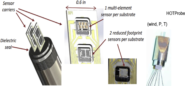
Table 2 provides some details on planned sensors. Temperature can be measured using a PtPt/Rh thermocouple sensitive up to 1500 °C or by other approaches (Wrbanek and Fralick, 2006; Wrbanek et al., 2012a,b), such as using the inherent characteristics of the electronics themselves. Pressure and wind are measured using strain sensors using a silicon carbide (SiC) diaphragm and thin film sensors respectively (Okojie et al., 2014; Hunter, 2016). Radiance is measured using high temperature bolometers. The atmospheric chemistry multisensor array is based on resistors, electrochemical cells, and Schottky diodes as required to detect each of the species Hunter (2016). These are miniaturized and micro-fabricated (Fig. 2) into arrays, typically 4-sides per array Chemical species sensors are designed to limit cross-sampling interference.
Fig. 2.
Atmospheric chemistry multisensor.
3.4. Surface morphology of the landing site
Each SAEVe station can carry two short duration cameras that operate at 800 nm wavelength. These cameras are commercial off the shelf (COTS) systems selected to achieve the morphology-science objectives described in Section 2. They are housed in temperature/pressure vessels to allow operation during descent operations and the short-term campaign of approximately 60 min after landing. One camera will look down to image the surface during descent and the second will be oriented off nadir to capture images of the seismic instrument and local morphology.
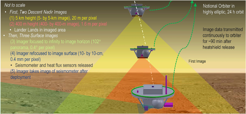
To assess landing site morphology, an image of the surface will be taken at ~5 km above the surface during descent and another image is taken at 400 m. The final landing site location will be visible in both these images assuming horizontal winds are ~1 m/s, which is consistent with prior data from Soviet landers (e.g., Ksanfomality et al., 1982).
In addition, two near field images will be taken at the surface. The first of these images of the surface serves two purposes: to examine the detailed morphology of the surface to look at rock, sediment type, and distribution as well as cements, and to examine the surface upon which the seismometer will be deployed in order to help assess surface contact. A second image of the same field will be taken after deployment of the seismometer so that it captures the seismometer and how it is resting on the surface.
The last (fifth) image to be taken will capture both the near field and the local horizon to look at morphology and topography of surface materials as well as landforms and structures in the scene.
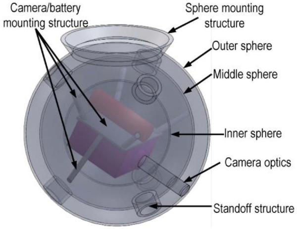
The SAEVe imaging system is designed to consist of two COTS cube sat cameras. Each is located in its own thermally protected camera pod. Each pod/camera system weighs about 2.5 kg. Even considering the limited life of the camera systems, the most significant technical challenge is the data volume that will need to be transmitted. The communication system bandwidth (Section 4) limits the speed the images can be sent to the orbiter before the camera electronics fail. However, by limiting the resolution to 256 × 256 pixels at 8 bits greyscale, the five desired images can to be returned in the available time.
One concept for a camera pod and its contents is shown in Fig. 3.
Fig. 3.
Camera pod concept.
3.5. Measurements summary
One additional instrument set is planned, although not described in detail because the concept and technology are at an early stage of development. This instrument is a set of sensors arranged in a certain pattern and tuned to maximize opportunity to “see” the sun. The objective is to determine if such an instrument could, over time, determine the sun’s path in the sky to provide lander orientation information. There is debate whether sun position can be determined. This instrument would allow answering that question with in-situ data, and allows for updating our models of the deep Venus atmosphere optical properties.
Table 2 presents a summary of the characteristics of the various sensors and instruments planned for SAEVe that were described in this section. The technologies needed to implement the SAEVe concept are currently in development by several funded activities. Component level work is ongoing under NASA’s HOTTech program but most directly SAEVe relevant technologies are “under development” by the LLISSE project (Kremic, 2017). LLISSE, which stands for Long Lived In situ Solar System Explorer, is a NASA project to develop a small Venus lander that will operate on the surface of Venus for 60 days capturing meteorology, radiance, and atmospheric chemistry variability. LLISSE is developing a full-function engineering model of a Venus lander with slightly fewer instruments and 60 day life goal, but otherwise is essentially all the core capabilities of SAEVe thus greatly reducing the technology risk to its completion. Table 2 reflects the development and targeted specifications ongoing in projects such as LLISSE.
4. SAEVe lander and mission design–a simple architecture
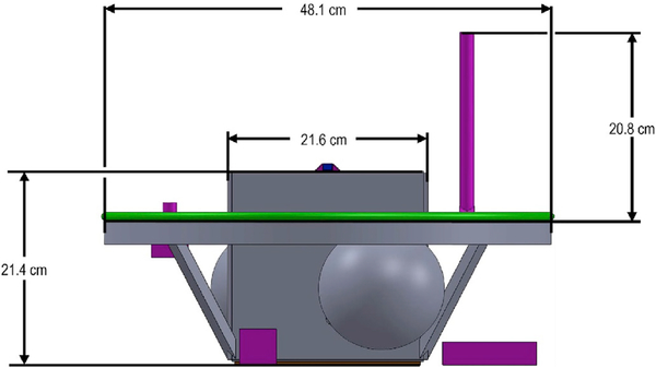
The SAEVe approach is to return important science via low-power instruments that generate low volumes of data. This philosophy is carried to the platform itself. A functional depiction and basic dimensions of the SAEVe lander concept was generated by the NASA Glenn COMPASS team and is shown in Fig. 4.
Fig. 4.
Basic physical dimensions.
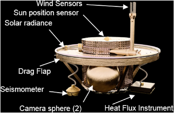
With the exception of the contents within the camera pods all components for the lander utilize high temperature materials and electronics suitable for the expected temperature, pressure, and chemical conditions in transit, entry, and while operating on the surface. There is no cooling required anywhere on the lander. The instruments/sensing elements are located as needed around the lander as shown in Fig. 5; their current technology readiness is listed later in Table 6.
Fig. 5.
SAEVe concept and instrument locations.
There are only three simple moving parts associated with the lander, one of these is the wind sensor arm, and the other is the pin release mechanisms for the seismometer and heat flux instruments. At the appropriate time, the wind sensor arm hold-down releases, and the arm goes to its instrument’s natural vertical position, and the other two drop the instruments the short distance between the drag flap and surface by the release pins that hold them in position.
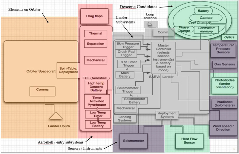
Communication is handled via a VHF system operating at between 100 and 150 MHz, similar to what was done on previous Venus landers. Data rates will be 200 bps or higher. SAEVe has transmit-only capability given its primary mission to provide unique, extended duration science data for the first time in a simple, low power platform that aims to maximize battery life. All operations to be conducted are predetermined before launch. Future iterations may consider some form of responsive interaction with the orbiter. An overall system diagram of SAEVe, its entry shell and the interface elements on the orbiter is shown in Fig. 6. Only one camera sphere is shown for simplicity.
Fig. 6.
SAEVe’s system schematic.
A high temperature battery [Landis, 2010, Burk, 1980] is assumed to power the lander for the desired life of SAEVe on Venus. The battery is not currently planned to be recharged, but has the energy required to execute the mission as shown in the energy usage summary in Table 3. There are promising capabilities being developed by NASA’s HOTTech program that may have applicability for recharging a battery on Venus. These capabilities will be monitored, and resulting power availability and usage is shown in Table 3.
Table 3.
Estimated battery energy available and its usage.
| Energy Available |
716 Wh |
|---|---|
| Usage | Energy |
| Descent from 5 km until Touchdown Energy | 3 Wh (<1%) |
| Touchdown Energy: | 5 Wh (<1%) |
| Science and Communication Energy | 157 Wh (22%) |
| Seismic Monitoring Energy | 465 Wh (66%) |
| Seismic Event Energy | 81 Wh (11%) |
| Total Power Available | 716 Wh |
Cost estimates were developed for building and implementing the SAEVe mission as described. This was done via the COMPASS concurrent engineering design team. In addition, the resulting design, minus the cost estimate, was provided to The Aerospace Corporation to develop an independent cost estimate. The two estimates were assessed for differences, and a combined estimate was established. Integration costs and liens for the orbiter hardware are included, but development to get to Technical Readiness Level (TRL) 6 is not. The cost for implementing SAEVe with two stations outfitted as described is estimated to be approximately $106 M in FY17 dollars. Table 4 compares estimates for descope options, such as a single station or dual stations with descoped payloads that eliminate camera-pod and heat flux sensors. These estimates are based on both internal and independent estimates.
Table 4.
Combined cost estimate.
| Estimates |
Full Payload, 2 landers |
Full Payload - Single Lander |
Reduced Payload - Single Lander |
|---|---|---|---|
| Combined | $106 | $87 | $71 |
| Notes: | -In $M dollars | ||
| -Development to TRL-6 not included | |||
| -Includes both subsystem growth margins and system margin wraps | |||
4.1. Mass summary
Mass summary by subsystem and growth allowances are shown in Table 5. The mass budgets include subsystem growth as shown. An additional growth of 5 percent is carried at the system level. The total predicted mass of the base SAEVe concept with growth is 28.5 kg. The total predicted mass the orbiter would release would be approximately 45 kg.
Table 5.
Lander: SAEVE total system, including EDL.
| SAEVe Master Equipment List (MEL) | Mass (kg) | Growth Allowance (%) | Growth Allowance (kg) | Mass plus Growth Allowance (kg) |
| Lander | 18.08 | 25.0% | 4.52 | 22.59 |
| Science | 1.21 | 30.0% | 0.36 | 1.58 |
| Attitude and Determine Control | 0.00 | 0.0% | 0.00 | 0.00 |
| Command and Data Handling | 0.38 | 30.0% | 0.11 | 0.49 |
| Communications and Tracking | 0.51 | 30.0% | 0.15 | 0.66 |
| Electrical Power Subsystem | 6.94 | 32.6% | 2.26 | 9.20 |
| Structures and Mechanisms | 9.04 | 18.0% | 1.63 | 10.67 |
| EDL | 13.68 | 18.5% | 2.53 | 16.21 |
| Electrical Power Subsystem | 0.40 | 35.0% | 0.14 | 0.54 |
| Thermal Control (Non-Propellant) | 13.3 | 18.0% | 2.40 | 15.70 |
| Camera-Sphere MEL (for 2 copies) | Mass (kg) | Growth (%) | Growth (kg) | Mass with growth (kg) |
| Cameras (2 pods) | 5.02 | 17.7% | 0.9 | 5.91 |
| Science | 0.18 | 30.0% | 0.1 | 0.23 |
| Thermal Control (Non-Propellant) | 3.00 | 18.0% | 0.5 | 3.6 |
| Electrical Power Subsystem | 0.05 | 36.7% | 0.0 | 0.07 |
| Structures and Mechanisms | 1.80 | 15.6% | 0.3 | 2.00 |
4.2. Mission design/architecture for delivery, entry, and landing
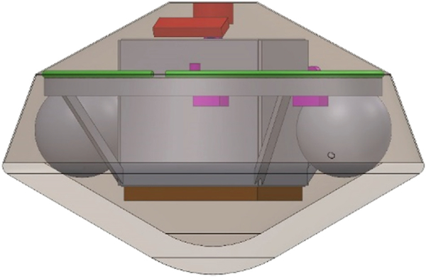
In the SAEVe Mission concept study we assume the landers would “ride along” with a Venus orbiter mission that would, along with its own science, provide relay capability for the 120 days that SAEVe would operate. The deployment, entry, and landing of SAEVe onto the Venus surface uses simple flight proven techniques and systems. The carrier spacecraft/orbiter will carry the SAEVe entry capsules (Fig. 7) on spin tables. Using the spin tables, at the appropriate times, the carrier spacecraft will spin up and release the capsules. No other interactions/control is required from the carrier vehicle during launch, transit, and release (approximately 3 weeks before orbit entry). As the capsules enter the Venus orbit, the aeroshells will provide all entry functions, and communicate entry events via their own battery and avionics. The release of the capsules by the orbiter would be executed and timed to allow the orbiter to be in view of the landers and track/relay all the critical events associated with release and entry.
Fig. 7.
SAEVe entry capsule system.
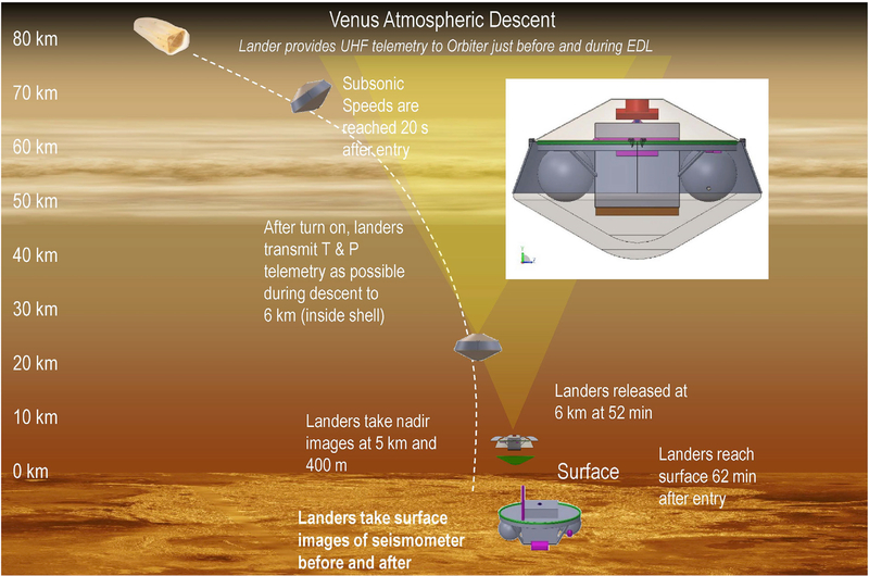
After successful entry of the 0.6 m diameter capsules, each will descend intact to approximately 6 km, at which time, the front and back shells separate. After the front shell is safely out of the way, the lander is then dropped from the back shell, and they naturally separate as they fall due to their mass and shape properties. There is no need for a parachute or other deceleration device on the landers. The thickening atmosphere, lander mass, and drag plate work together to safely bring the landers to the surface with a touchdown velocity of approximately 6 m/s. The lander commences science during the last phase of descent as described earlier. The total time for descent from entry is approximately 62 min (Fig. 8). Section 5.2 describes the lander operations once it reaches the surface.
Fig. 8.
SAEVe entry sequence.
5. Potential landing sites and rationale
Because SAEVe would be the first long-lived lander on the Venus surface, virtually any location on the surface would be an attractive science target. Among the instruments in the SAEVe payload, the seismometer would most benefit from a specifically targeted landing site. Geophysical observations suggest that the Beta Regio/Devana Chasma/Phoebe Regio and the Atla Regio regions are strongly supported by up-welling mantle plumes (Smrekar et al., 1997; Kiefer and Peterson, 2003; Kiefer and Swafford, 2006). This enhances the likelihood of current seismic activity in this region, which makes them high priority targets for a first Venus seismic mission. Because smooth landing sites are desired for safety, reasonable targets would be in the regional plains near Beta and Atla. Possible volcanic outgassing in either Beta or Atla could potentially be detected by the SAEVe atmospheric chemistry sensors. The high, mountainous plateau of Ishtar Terra has a crust that is relatively thick and possibly different in composition (more silica rich) than most of Venus’s crust. This makes Ishtar an attractive target for seismic exploration, and the flat Lakshmi Planum plateau would provide a safe landing zone. It is recognized that if SAEVe is a ride-along secondary payload on another mission, then the SAEVe landing zone will be constrained by the orbital mechanics requirements of the primary payload. For this reason, we emphasize that landing sites anywhere on Venus would be scientifically valuable.
5.1. Assumptions on the orbiter
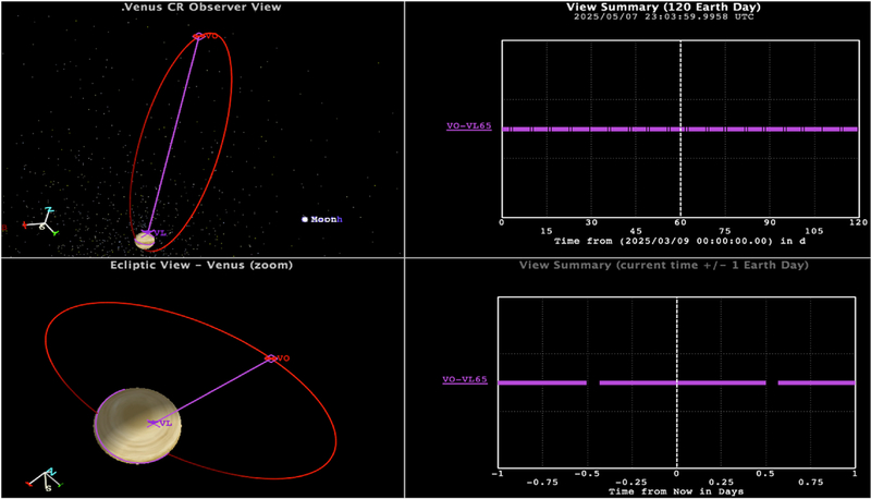
Because SAEVe relies on a yet undefined orbiter to provide relay communications, some assumptions have been made. One assumption is the orbiter will be in a 24 h elliptical orbit (500 by 66,409 km) as seen with Venus Express (Venus Express Mission, 2009). This is a reasonable orbit assumption because of prior missions and future missions under consideration. If the orbit/landing is chosen such that the orbiter is over the lander at day 60 of the mission, a maximum possible communication link time of 23.5 h is available during each orbit (Fig. 9).
Fig. 9.
Assumed orbit and resulting contact times between lander and orbiter.
The amount of contact time between the orbiter and lander will be determined by the actual orbit selected by the host mission and lander locations on the planet. Given the significant science SAEVe will contribute (as indicated in Table 1), it is expected that for a mission focused on advancing studies of Venus’ seismicity and near-surface meteorology, the orbit will be chosen in part to help maximize the science return from SAEVe.
Because SAEVe relies on a simple periodic schedule to transmit data, the orbiter will know when to listen for the transmissions. This keeps operational uncertainty low so orbiter operations can be planned well ahead of time and any negative impacts to orbiter science minimized. It is understood that seismic events are transmitted as they occur and are unpredicted. Some events will not be captured by the orbiter, but given the number of events expected over 120 days from models (Lorenz, 2012) and the potential for significant communication coverage, there is strong expectation that data from most of the detectable events can be returned.
5.2. Concept of surface operations
The surface operations plan is designed to achieve the science goals summarized in section 2.1 while optimizing resource usage. The most restrictive resource is energy stored in the battery. As soon as the lander is released from the aeroshell, it begins taking and transmitting images and the descent temperature, pressure, and chemistry measurements. A high priority is returning the five images that will be taken with the short duration cameras, see Fig. 10. Five minutes will be allotted after touchdown for any dust to settle before the three images at the surface are taken. At the resolution planned, each image takes no more than 17 min to transmit.
Fig. 10.
Summary of SAEVe imaging plan.
The image data are written to onboard camera memory in the camera “pods,” but these memory modules will stop operating once the temperature exceeds their operational range. This is predicted to happen 90 min after landing. By this time all images would have been transmitted.
Fig. 11 portrays a notional timeline of science operations. All the payloads not already active (the seismometer, wind sensors, and heat flux sensor) are deployed shortly after landing. Once deployed, all instruments will be ready to start continuous transmitting (Mode 2), which begins as soon as the last image is transmitted. In this mode, all three seismometer axis and meteorological and atmospheric composition sensors acquire and transmit measurements for a 60 min period. This initial period allows first-order meteorological and seismic characterization of the landing site. All data are transmitted in near-real time. Heat flux measurement will not be taken at this time to ensure enough time elapses for all hardware to reach equilibrium conditions.
Fig. 11.
Notional science operations timeline – not to scale.
To characterize the variation of parameters over a complete Venus solar day (118 Earth days), after mode 2 is complete, SAEVe enters a low power normal operations mode (Mode 3). In this mode, the probe wakes up once every 8 h and acquires 2 min of data. The data obtained in this mode are timed to enable the extended operating life and to meet science requirements for the nature of the measurements taken. Data are, again, transmitted in near-real time.
In normal long duration operations mode, the seismometer will be continuously on and “listening” for an event. As described earlier, in this mode the vertical-axis seismometer is monitored by a low power circuit; if a threshold criterion is exceeded, then the lander will start acquiring and transmitting seismic data.
The threshold criterion used to trigger seismic data collection will be carefully defined, so as to avoid too frequent or too infrequent triggers. The energy budget allows for 50 seismic events to be recorded during the 120-day nominal mission. As shown in Fig. 6, there is a separate battery for seismometer operations. The purpose of this is to ensure that an unexpected large number of events, due to high levels of seismic activity or undetected wind triggers, do not impact the 120 day meteorology and heat flux related science objectives of the mission.
6. Technical readiness
The SAEVe lander concept takes advantage of ongoing technology and system developments. Most notably, many of the capabilities SAEVe requires to realize its science goals are being developed and or proven through the ongoing Long-Lived In-situ Solar System Explorer (LLISSE) project (Kremic, 2017). The basic aspects of the SAEVe lander are similar to LLISSE and key capabilities (e.g., battery, most sensors, and communication system) will be developed and demonstrated in Venus simulated environments as part of LLISSE development. In order to understand the technical readiness of many of SAEVe subsystems and instruments, progress on the LLISSE project can be assessed. One then needs to assess the technical readiness of the remaining specific technology components used on SAEVe that are not a part of LLISSE. Table 7 provides a summary of the key technologies on SAEVe, and reflects where (LLISSE or another project) work is ongoing, if at all.
Table 7.
Technology readiness for instrument and critical subsystems.
| Technology | Current TRL | Estimated to be at TRL 6 | Funding Source: Ongoing (O) (to TRL 6) and Potential (P) |
|---|---|---|---|
| Electronic circuits (SiC): sensors and data handling | 4–5 | 2021 | LLISSE (O) |
| Electronic circuits (SiC): power management | 3–4 | 2021 | LLISSE (O) |
| Communications (100 MHz) | 3–4 | 2021 | LLISSE (O) |
| Wind Sensor | 4 | 2021 | LLISSE (O) |
| Temperature Sensor | 6 | 2021 | LLISSE (O) |
| Pressure Sensor | 4–5 | 2021 | LLISSE (O) |
| Chemical Sensors | 5 | 2021 | LLISSE/HOTTech (O) |
| LLISSE Bolometer | 3–4 | 2021 | LLISSE (O) |
| Seismometer | 3 | TBD | LLISSE (O) and possibly Maturation of Instruments for Solar System Exploration (MaTISSE) (P) |
| Heat Flux Sensor | 3–4 | TBD | Planetary Instrument Concepts for the Advancement of Solar System Observations (PICASSO) (O)—MaTISSE |
| Camera/imaging System | 3–4 | TBD | Rocket University (O)–PICASSO and MaTISSE as needed |
| Solar Radiance | 4 | 2021 | LLISSE (O) |
| High-Temperature Battery | 3–4 | 2021 | LLISSE (O) and HOTTech (O) |
| Entry Shell | 6 | Complete | Heatshield for Extreme Entry Environment Technology (HEEET)–Will need SAEVe specific system design |
The TRLs and dates are estimates and meant to provide a relative measure of the maturity of the overall SAEVe system. As with all estimates of future events, they are subject to funding and technical progress. Because specific mission or launch details are not available, one cannot determine certain parameters (e.g., vibration levels) necessary to demonstrate complete readiness to TRL 6. Therefore, for purposes of this assessment, TRL 6 is based on ability to meet goals of mission life at Venus surface temperature, pressure and atmospheric chemistry. These objectives are the drivers for a Venus surface mission, and therefore, is a reasonable metric for this paper.
7. Conclusions
SAEVe capitalizes on 1) the latest developments in high temperature sensors and electronics; 2) carefully selected and focused science objectives that follow a theme of temporal based science achievable with low volumes of data and 3) a novel operations approach to achieve its objectives. The innovative combination of these three elements will allow SAEVe to operate on the surface of Venus for a full solar day (~120 days, as opposed to ~ 2 h, as has been done to date). It will return science that helps us start tackling important science questions including: 1) seismic activity 2) crust thickness and composition, 3) meteorology and its potential local solar time variability, 4) momentum exchange between the atmosphere and planet, which helps get at superrotation, 5) chemical variability (relative to local solar time or otherwise), 6) energy balance at the surface, and 7) morphology.
This baseline mission can be realized with the two landers deployed 300–800 km apart. The two independent cost estimates for this novel mission architecture and concept predict that SAEVe will cost $106 M.
As with any mission concept there are risks. The most significant is that we have little knowledge of Venus’ seismic activity. The frequency and magnitude may be far different than anticipated. This would impact how long seismic measurements can be taken, or may result in not capturing events. This risk will be true for any mission. In many ways, SAEVe is an ideal mission to resolve this environmental issue. SAEVe will provide the data needed to design and plan future missions.
One of the factors that support the possibility of a future SAEVe mission is that almost all the technology developments that are needed to realize SAEVe science objectives are in work. For example, the power, electronics, communication systems, and structure required by SAEVe are already in development with plans to demonstrate performance at Venus conditions. The same is true for most of the sensors. The heat flux and seismometer have had some development, although for these two instruments, their current funding does not cover development to TRL 6.
SAEVe is an exciting mission that offers the potential for addressing long-standing science questions in a unique and innovative way. Benefits are: low relative cost, relative ease of integration onto a Venus orbiter mission, novel science, and serving as a pathfinder for understanding the Venus surface and interior. This will allow even more sophisticated future landers to be successful with their objectives.
Supplementary Material
Acknowledgements
The authors acknowledge the funding support provided by NASA’s Planetary Science Deep Space Smallsat Studies program. The authors also acknowledge the COMPASS team members at the NASA John H. Glenn Research Center for their valuable contributions toward the definition of this concept.
Footnotes
Declaration of competing interest
The authors declare that they have no known competing financial interests or personal relationships that could have appeared to influence the work reported in this paper.
Appendix A. Supplementary data
Supplementary data to this article can be found online at https://doi.org/10.1016/j.pss.2020.104961.
References
- Avduevskii VS, Vishnevetskii SL, Golov IA, et al. , 1976. Venera 9 and 10 surface wind-velocity measurementsKosm. Issled 14, 710–713. Cosmic Res. 14, 622–625. [Google Scholar]
- Burk J, 1980. 4th DOE/EPRI Sodium-Sulfur Battery Workshop. [Google Scholar]
- Garvin James B., Head James W., Zuber Maria T., Paul Helfenstei, 1977. Venus’ the nature of the surface from Venera panoramas. J. Geophys. Res. 89 (B5), 3381–3399. May 10, 1984. [Google Scholar]
- Hunter G, 2016. High temperature rad-hard electronics, atmospheric measurements, and sensor systems for Venus exploration and other planetary missions. In: New Frontiers 4 Technology Workshop, June 1, 2016, Washington, DC. [Google Scholar]
- Kiefer Walter S., Peterson Kelly, 2003. Mantle and crustal structure in phoebe Regio and devana Chasma, Venus. Geophys. Res. Lett. 30 10.1029/2002GL015762, 2003. [DOI] [Google Scholar]
- Kiefer Walter S., Swafford Laura C., 2006. Topographic analysis of Devana Chasma, Venus: implications for rift system segmentation and propagation. J. Struct. Geol. 28, 2144–2155. [Google Scholar]
- Kremic Tibor, et al. , 2017. Long-life in-situ solar system explorer (LLISSE) probe concept and enabling high temperature electronics. Lunar Planet. Sci. Conf. https://www.hou.usra.edu/meetings/lpsc2017/pdf/2986.pdf. [Google Scholar]
- Ksanfomality, et al. , 1982. Acoustic measurements of the wind velocity at the VENERA-13 and VENERA-14 landing sites. Sov. Astron. Lett 8 (July-Aug. 1982), 227–229. Translation Pisma v Astronomicheskii Zhurnal, vol. 8, July 1982, pp. 419–423. [Google Scholar]
- Landis Geoff, Harrison R, 2010. Landis GA, and Harrison R, “Batteries for Venus surface operation.” Journal Of Propulsion And Power, Vol. 26, No. 4, July–August 2010. Journal of Propulsion and Power 26 (No. 4). In press. [Google Scholar]
- Lebonnois, et al. , 2018. Planetary boundary layer and slope winds on Venus. Icarus. 10.1016/j.icarus.2018.06.006. [DOI] [Google Scholar]
- Logonné P, et al. , 2019. Space Sci. Rev. 215 (12), 2–170. [DOI] [PMC free article] [PubMed] [Google Scholar]
- Logonné Philippé, et al. , 2018. https://www.seis-insight.eu/en/public-2/seis-instrument/inner-working.
- Lorenz Ralph D., 2012. Planetary seismology–Expectations for lander and wind noise with application to Venus. Planet. Space Sci. 62, 86–96. [Google Scholar]
- Navarro T, Schubert G, Lebonnois S, 2018. Atmospheric mountain wave generation on Venus and its influence of the solid planet’s rotation rate. Nat. Geosci 10.1038/s41561-018-0157-x. [DOI] [Google Scholar]
- Okojie Robert S., Meredith Roger D., Chang Clarence T., Savrun Ender, 2014. High temperature dynamic pressure measurements using silicon carbide pressure sensors. In: Proceedings 2014 IMAPS International High Temperature Electronics Conference, pp. 47–52. [Google Scholar]
- Pauken Michael, Smith Kevin L., Sujittosakul Sutine, Phan Brian, Firdosy Samad, Li Billy Chun-Yip, George Nakatsukasa, Fleurial Jean-Pierre, Smrekar Suzanne, 2017. A thermopile based heat flux sensor for measuring heat flow on the surface of Venus. In: Oral Presentation at 14th International Planetary Probe Workshop. IPPW. June 12–16. [Google Scholar]
- Shalygin EV, et al. , 2015. Active volcanism on Venus in the ganiki Chasma rift zone. First published: 23 may 2015. Geophys. Res. Lett. 42, 4762–4769. 10.1002/2015GL064088. [DOI] [Google Scholar]
- Shapiro NM, Campillo M, Stehly L, Ritzwoller MH, 2005. High-resolution surfacewave tomography from ambient seismic noise. Science 307, 1615–1618. [DOI] [PubMed] [Google Scholar]
- Smrekar SE, et al. , 2010. Recent hotspot volcanism on Venus from VIRTIS emissivity data. Science 328, 605–608. [DOI] [PubMed] [Google Scholar]
- Smrekar Suzanne E., Kiefer Walter S., Stofan Ellen R., 1997. Large volcanic rises on Venus. In: Bougher SW, Hunten DM, Phillips RJ (Eds.), Venus II: Geology, Geophysics, Atmosphere, and Solar Wind Environment. University of Arizona Press, pp. 845–878. [Google Scholar]
- Venus express mission, European Space agency, 2009. for example, see: https://ui.adsabs.harvard.edu/abs/2009JGRE.114.0B33S/abstract.
- Visions and Voyages for Planetary Science in the Decade vols. 2013–2022. 2011. National Research Council. [Google Scholar]
- VEXAG, goals, objectives, and investigations, 2019. May 2014, Revised, 2019. https://www.lpi.usra.edu/vexag/reports/GOI-Space-Physics-Update-0816.pdf.
- Williams David R., 2019. NASA chronology of Venus exploration 2/22/2019. https://nssdc.gsfc.nasa.gov/planetary/chronology_venus.html, 7/24/2019.
- Wrbanek John D., Fralick Gustave C., 2006. Thin Film Physical Sensor Instrumentation Research and Development at NASA Glenn Research Center. NASA/TM, 2006–214395, ISA# TP06IIS023 (September 2006). [Google Scholar]
- Wrbanek John D., Fralick Gustave C., Zhu Dongmin, 2012. Ceramic thin film thermocouples for SiC-based ceramic matrix composites. Thin Solid Films 520 (2012), 5801–5806. [Google Scholar]
Associated Data
This section collects any data citations, data availability statements, or supplementary materials included in this article.


