Abstract
A novel and recoverable platform of polyurethane (PU) sponge-supported Au nanoparticle catalyst was obtained by a water-based in-situ preparation process. The structure, chemical, and morphology properties of this platform were characterized by XRD, TGA, SEM, FT-IR, and XPS. The Au/PU sponge platform exhibited excellent catalytic performances in catalytic reductions of p-nitrophenol and o-nitroaniline at room temperature, and both catalytic reactions could be completed within 4.5 and 1.5 min, respectively. Furthermore, the strong interaction between Au nanoparticles and the PU sponge enabled the catalyst system to maintain a high catalytic efficiency after 5 recycling times, since the PU sponge reduced the trend of leaching and aggregation of Au nanoparticles. The unique nature of Au nanoparticles and the porous PU sponge along with their strong interaction resulted in a highly efficient, recoverable, and cost-effective multifunctional catalyst. The AuNP/Sponge nanocatalyst platform has great potential for wide environmental and other catalytic applications.
Keywords: environmental degradation, Au nanoparticles, polyurethane sponge, catalysis reduction, nitroaromatic compounds
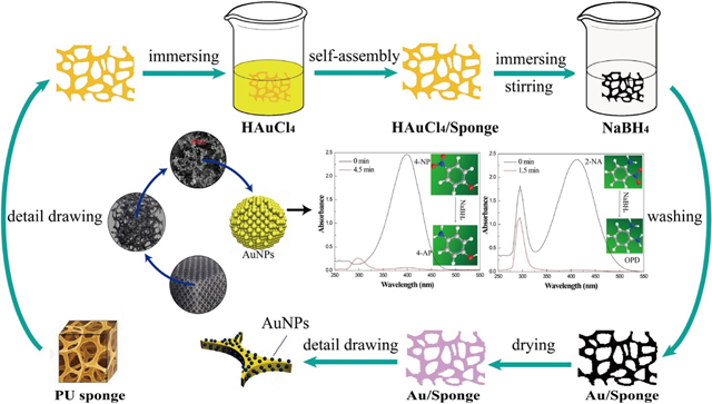
Graphical Abstract
1. Introduction
Noble metal nanoparticles (NPs) have attracted growing attention in various fields including catalysis, environmental remedy, biomass conversion, and biomedical applications [1–4], due to their unique size and shape effect.[5–9] As an example, nano palladium-based catalysts have been applied for various organic reactions, such as primary amides synthesis and oxidative amidation reactions.[10–12] Because of the isoelectronic nature and acidic character of gold with palladium species, researchers have extensively investigated Au nanomaterials.[13, 14] Hashmi explained the role of Au nanoparticles (AuNPs) for organic transformations toward heterogeneous catalysis.[15] Thereafter, Au nanocatalysts have been applied for tremendous fields of organic transformation, including nitroaromatic compounds reduction,[16, 17] CO oxidation,[18, 19] carbon-carbon coupling reactions,[20, 21] and so on. To decompose nitroaromatic compounds for environmental remedy, catalysts need to meet several vital requirements before their industrial and other practical applications: (1) excellent catalytic performance; (2) robust and efficient separation strategy from nitroaromatic compound solutions; (3) long-term stability when immersing in the aqueous phase. However, noble metal nanocatalysts suffer a dilemma to meet these requirements: it is very difficult to increase their catalytic efficiency and reusability simultaneously. Aqueous-phase catalysts can reach high catalytic efficiency, but separation remains a big challenge. Solid-phase catalysts are uncomplicated to separate but their catalytic efficiency is compromised by uneven dispersion. In addition, numerous solid-phase catalysts often become disintegrated in the prolong course when being immersed in water. Despite intensive research, there is still an urgent need to develop novel catalysts with high catalytic efficiency and reusability for nitroaromatic compounds degradation to meet the increasing demand from environmental applications.
The porous polyurethane (PU) sponge, a macromolecule polymer material with long-term stability in water, can serve as a good catalytic carrier. Meanwhile, PU sponge has amino groups on branched chains and its hydrophilicity facilitates catalytic reactions in water. In addition, polymer-based catalysts possess an advantage of facile isolation of products and catalysts can be recovered through a simple re-precipitation/filtration method with proper solvents rather than laborious procedures such as chromatographic separation.[22] Owing to these merits, the PU sponge is an excellent catalytic carrier for the decomposition of nitroaromatic compounds and other catalytic applications. Although PU sponge has been utilized in some catalytic fields such as the removal of methylene blue,[23] it has never been used for the nitroaromatic compound catalysis. Furthermore, AuNPs, known as an excellent electron-donor or acceptor, exhibits excellent chemical inertness and could stay stable under various reaction ambiance,[24] and have the potential to promote catalytical reductions of nitroaromatic compounds significantly. [25, 26] Therefore, we hypothesize that AuNPs modified PU sponge (AuNP/Sponge) could exhibit excellent catalytic performance to degrade nitroaromatic compounds with high reusability.
It is well known that nitroaromatic compounds, especially p-nitrophenol (4-NP) and o-nitroaniline (2-NA), are major contributors to worsening environment issues such as water contaminants, which would trigger teratogens, mutagens, and carcinogens.[27, 28] Accordingly, a diverse set of nitroaromatic compounds have been encompassed in environmental legislation.[29] On the other hand, p-aminophenol (4-AP) and o-phenylenediamine (OPD) are crucial intermediates that enable widespread applications in manufacturing fine chemicals and end products, including antipyretic drugs, photographic developer, and corrosion inhibitor.[30–32] The catalytic reduction of nitroaromatic compounds do not only possess great ecological and environmental significance but also important economic values.[33, 34] Hence, 4-NP and 2-NA were chosen as model systems to demonstrate the performance of the AuNP/Sponge catalyst for catalytic reduction of nitroaromatic compounds.
Herein, we report a novel high-efficiency and high-reusability AuNP/Sponge catalyst prepared with a facile one-step process for cost-effective catalytic reduction of nitroaromatic compounds. AuNPs were generated on the surface of PU sponge via a water-based in-situ preparation process, because of the strong interaction of AuNPs and PU sponge, and thereafter their catalytic performances in the reduction of 4-NP and 2-NA were systematically studied. The Au/ PU sponge catalyst platform can finish the 4-NP reduction within 4.5 min and 2-NA reduction within 1.5 min, while keeping high catalytic efficiency even after five recycles of catalysis. In addition, their chemical, structure, and morphology properties were characterized by XRD, TGA, SEM, FT-IR, and XPS. The unique properties of Au nanoparticles and the porous PU sponge along with their strong interaction resulted in a highly efficient, recoverable, and cost-effective multifunctional catalyst.
2. Experiment
2.1. Materials
Sodium borohydride (NaBH4, 98%) was purchased from Alfa Aesar (Tewksbury, MA). P-nitrophenol (4-NP) and o-nitroaniline (2-NA) were purchased from EMD Millipore Corporation (Billerica, MA). Gold (III) chloride trihydrate (HAuCl4·3H2O) was purchased from Sigma (St. Louis, MO). The polyurethane sponge was purchased from Haofeng, China. Water with a resistivity of 18.2 MΩ.cm@25 °C was from a Millipore Milli-Q system (Bedford, MA). All chemicals were of analytical grade and used without further processing.
2.2. Catalyst preparation
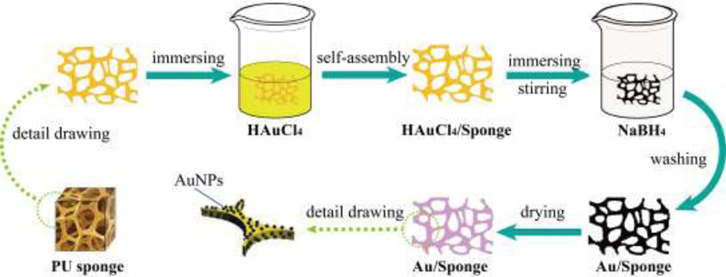
Scheme 1 and Scheme S1 presented the preparation process of the AuNP/Sponge catalyst. The water-based in-situ preparation process was simple and versatile. Firstly, the sponge was cut into the square with a dimension of 1.5×1.5 cm2 (about 75 mg). An appropriate amount of HAuCl4·3H2O (60 mg, 40 mg, 20 mg, and 10 mg, respectively) was added into 3 mL ultrapure water to obtain a HAuCl4 yellow clarified solution. Secondly, the sponge was compressed to eliminate air bubbles, and in turn, the HAuCl4 solution was absorbed by the sponge. Thirdly, an appropriate amount of NaBH4 was added into 5 mL ultrapure water to obtain a solution. Then, as a mixed precursor, HAuCl4/Sponge was rapidly added into a NaBH4 solution and kept vigorous stirring by a vortex mixer for 30 min to completely reduce Au3+. At last, the resulting black sponge from different amounts of Au ranging from 10 to 60 mg HAuCl4·3H2O was washed and vacuum dried to obtain a purple AuNP/Sponge catalyst (hereafter denoted as PU sponge, 10AuNP/Sponge, 20AuNP/Sponge, 40AuNP/Sponge, and 60AuNP/Sponge, respectively).
Scheme.1.
Preparation of the AuNP/Sponge catalyst.
2.3. Catalytic activity measurement
The catalytic efficiency of the AuNP/Sponge platform was investigated by using 4-NP conversion to 4-AP and 2-NA conversion to OPD. As an example of 2-NA conversion to OPD, a quintessential procedure was adopted to carry out the chemical reaction. Firstly, a 2-NA solution (4 mM, 5 mL) and a NaBH4 solution (0.4 M, 5 mL) were added to the conical centrifuge tube (50 mL, Thermo Fisher Scientific, America) and mixed together. Secondly, the AuNP/Sponge platform was placed in a mixed solution and kept vigorous stirring by using a vortex mixer (Thermo Fisher Scientific, America). Afterward, 100 μL mixed solutions were transferred in a 96 well microplate (Thermo Fisher Scientific, America) by using a micropipette. The microplate was placed in a UV-visible spectrophotometer (Microplate reader M3, Molecular Devices, San Jose, CA) to measure its absorbance spectra. The remaining fraction of 2-NA (X) was calculated by the equation (1).
| Eq. (1) |
Where C0 was the initial 2-NA concentration and Ct was the concentration at different time intervals (t). Furthermore, the AuNP/Sponge catalyst was recycled for 6 times to investigate its reusability. For every recycle, the used catalyst was washed and vacuum dried for the next experiment. A similar procedure was adopted for the 4-NP reduction. The concentrations of 4-NP (1 mM) and NaBH4 (0.1 M) prepared for the experiment were 1 mM and 0.1M, respectively.
2.4. Characterization
X-ray diffraction (XRD) patterns were obtained on an X-ray diffractometer (Smartlab TM 3Kw, Rigaku, Japan), with a scan speed of 5 °·min−1 and a 5–80 ° 2θ scan. The microstructural nature of the catalysts was investigated using a field emission instrument scanning electron microscope (S-4800, Hitachi, Japan). Fourier transform infrared (FT-IR) spectra were evaluated by a Nicolet Nexus 670 series FT-IR spectrophotometer in an ATR mode. The spectra were recorded under ambient conditions over the range of 750–4000 cm−1 with a resolution of 0.5 cm−1. The thermogravimetric analysis was measured by a TGA system (Mettler Toledo International Inc, America). Before the measurement, the sample was dried at 80 °C for 2 h and a ceramic crucible was pre-treated by high-temperature sintering. The 0.5 mg sample was placed in the ceramic crucible and kept on the auto-sample stage of the TGA system. Then, the sample was heated from 30 °C to 1000 °C at a 10 °C·min−1 heating rate. The gas flow rate of the nitrogen atmosphere was 20 mL·min−1.
3. Results and discussion
3.1. Catalytic reduction of 2-NA
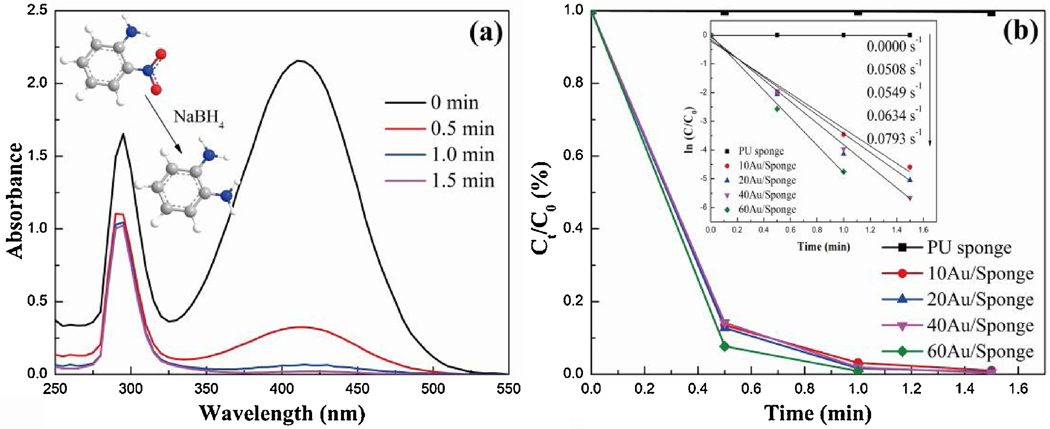
During the catalytic experiment by the Au/PU sponge, the yellow color of a 2-NA/NaBH4 solution faded and bleached ultimately with the addition of the AuNP/Sponge catalyst. The fading time decreased with the increase of the AuNPs amount, and the effect of AuNPs amount was monitored by the UV-Vis spectrophotometry. As shown in Fig. 1 and Fig. S1, the peak intensity at 410 nm decreased obviously and that at 295 nm decreased slightly with the increasing time. The literature confirmed that the peak at 410 nm represented 2-NA.[35] Therefore, the change of peak intensity was due to the transformation from 2-NA to OPD when the AuNP/Sponge catalyst was added into the 2-NA/NaBH4 solution. In addition, the peak intensity representing the 2-NA displayed no change in the absence of AuNPs in Fig. S2, suggesting that the PU sponge had no catalytic effect and AuNPs were essential for the catalytic reduction. Furthermore, the conversion rate of the 60AuNP/Sponge could reach 100.0% within 1 min. The catalytic efficiency decreased gradually when the AuNPs amount reduced. However, the conversion rate of 10AuNP/Sponge could still reach 99.0% within 1.5 min, indicating excellent performance for the catalytic reduction. In other words, the AuNP/Sponge was an excellent catalyst for catalytic reduction of nitroaromatic compounds.
Fig. 1.
(a) UV-vis absorption spectra of 2-NA reduction over 40AuNP/Sponge catalyst and (b) Ct/C0 vs. time plot.
The catalytic reduction reaction from 2-NA to OPD followed the first-order kinetic because of the excess amount of NaBH4. The kinetic was calculated by equation (2).
| Eq. (2) |
Where C0 was the initial 2-NA concentration, Ct was the concentration at different time intervals (t) and k was the apparent rate constant of the reaction. Fig. 1(b) also displayed the first-order kinetic curves of 2-NA over AuNP/Sponge with different AuNPs amounts. It could be observed that the data points generally followed the linearity, which was due to the vigorous stirring by using a vortex mixer during the period of the catalytic activity measurement. As such, the bubbles produced in the conical centrifuge tube could be eliminated in time. Furthermore, the value of k was 0.0793, 0.0634, 0.0549 and 0.0508 s−1, respectively.
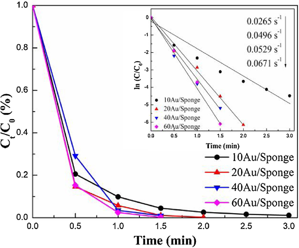
To compare the reusability and determine the optimal catalyst cycles, the used AuNP/Sponge catalysts were washed and vacuum dried for the second recycling time. Fig. S3 displays the UV-Vis absorption spectra of 2-NA reduction for a second recycling time and Fig. 2 shows the Ct/C0 and ln(Ct/C0) vs. time plot representing first-order kinetics. Compared with fresh AuNP/Sponge, all the experiments needed more time to complete the catalytic reduction and the catalytic efficiency decreased slightly. The conversion rate of 60AuNP/Sponge needed 1.5 min to reach 100.0%, while that of 10AuNP/Sponge reached 98.9% within 3 min. As generally known, the interaction between AuNPs with PU sponge is a collective effect between chemical bonds and physical adsorption. Accordingly, a small amount of AuNPs physically adsorbed on PU could break off from the PU sponge during the prolong use so that the active component reduced, and the catalytic efficiency decreased gradually. Both conversion rates from 40AuNP/Sponge and 60AuNP/Sponge reached nearly 100.0% within 1.5 min. Considering that 60AuNP/Sponge had a greater AuNPS loss than 40AuNP/Sponge, the 40AuNP/Sponge as chosen as the optimal catalyst. It can also be seen from Figure 2 that the data points also followed the linearity, and the value of k was 0.0671, 0.0529, 0.0496 and 0.0265 s−1 for the 60AuNP/Sponge, 40AuNP/Sponge, 20AuNP/Sponge, and 10AuNP/Sponge, respectively. They were slightly lower than those K values from fresh AuNP/Sponge.
Fig. 2.
Ct/C0 vs. time plot of the 2-NA reduction for a second recycle.
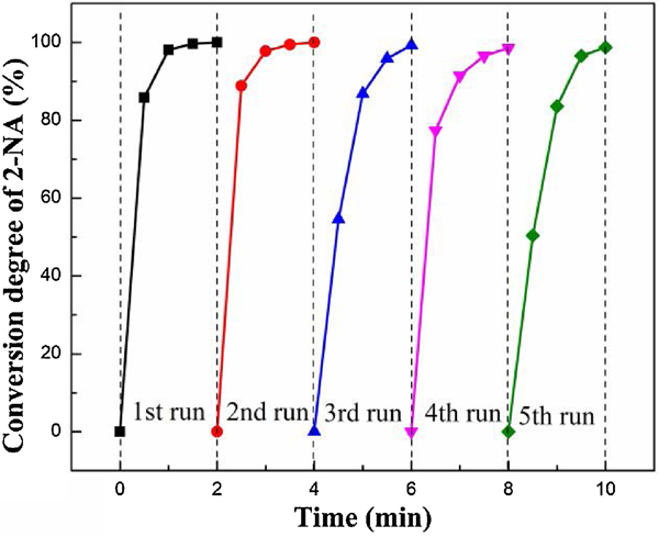
The major benefits of heterogeneous catalysts are their separation convenience from the reaction medium and reusability in consecutive runs.[36] In the present case, the reusability of 40AuNP/Sponge was investigated in detail (Fig. 3), and the used catalyst was washed and vacuum dried for the subsequent experiments. As shown in Fig. 3 and Fig. S4, all the 2-NA reduction could be completed within 2 min and the declining trend of conversion rate slowed with the increase of the recycling number. It was mainly because there were fewer AuNPs physically adsorbed on the surface of the AuNP/Sponge catalyst. The chemical bond became the dominant interaction between AuNPs and sponge gradually. Furthermore, the conversion rate of the 40AuNP/Sponge catalyst could reach 98.7% at the fifth recycling time. Compared with other catalysts, such as Cu2O@h-BN (50% activity loss after 4 recycling times),[37] Ni NPs in hydrogel network (25% activity loss after 5 recycling times),[38] and Ag/CH-FP (10% activity loss after 4 recycling times),[39] the 40AuNP/Sponge catalyst exhibited significantly better reusability. It was probably because the PU sponge could reduce the chances of leaching and aggregation for AuNPs.
Fig. 3.
Effect of recycling time on catalytic reduction of 2-NA over the 40AuNP/Sponge catalyst.
The catalyst exhibited lower and lower efficiency after each recycling time. Therefore, the waste catalyst formed if the catalytic efficiency could not satisfy the requirement. In this work, it was defined as the waste catalyst when the fresh 40AuNP/Sponge catalyst was reused for 8 times, and the regeneration capacity was investigated. For the regeneration of the waste catalyst, 2 mg, 4 mg and 6 mg (5%, 10% and 15% of Au amounts for the fresh catalyst, respectively) HAuCl4·3H2O were added into 3 mL ultrapure water, respectively. While the waste catalyst was compressed to eliminate air bubbles, an appropriate amount of NaBH4 was added into 5 mL ultrapure water to obtain the solution. Then, the HAuCl4/waste catalyst was added into the NaBH4 solution rapidly and kept vigorous stirring by a vortex mixer for 30 min. At last, the resulted sample was washed and vacuum dried to obtain the regenerated 40AuNP/Sponge catalyst (hereafter denoted as a waste catalyst, 5% Au regeneration, 10% Au regeneration and 15% Au regeneration, respectively).
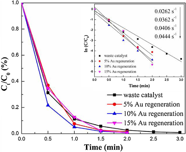
Fig. 4 and Fig. S5 showed the catalytic performance of the waste catalyst and regenerated catalysts for the 2-NA conversion. As shown in Fig. 4, the 2-NA conversion of waste catalysts could reach nearly 100.0% within 3 min and its apparent rate (k value) was 0.0262 s-1. In contrast, all the regenerated catalysts could finish the reaction within 2 min, and their k value recovered to 0.0362 s−1, 0.0406 s−1, and 0.0444 s−1, respectively. In consideration of economic and catalytic efficiency, 10% Au regeneration was chosen as the optimal regeneration condition, which was similar to that of the catalyst at the third recycling time. There were two possible reasons for the decrease of the catalytic efficiency after a few recycling times: (1) aggregation of Au nanoparticles; (2) the loss of a small amount of AuNPs from the PU sponge. The waste catalyst could recover higher catalytic efficiency by loading a small quantity of Au, but it was found that the efficiency of the regenerated catalyst could not be as high as that of a fresh one. Furthermore, the catalytic performance of the 40AuNP/Sponge in a flow-through mode was investigated and the result was shown in Fig. S6. It can be seen that the catalytic efficiencies of 2-NA over 40AuNP/Sponge reached about 100% even if the injection speed was at 0.5 mL·min−1, which was higher than that of AuNPs-anchored paper [40]. In summary, the AuNP/Sponge catalyst exhibited outstanding reusability and regeneration capacity, even though a slight decrease in catalytic efficiency was observed.
Fig.4.
Ct/C0 vs. time plot of the 2-NA reduction by the waste catalyst and regenerated catalysts.
3.2. Catalytic reduction for 4-NP
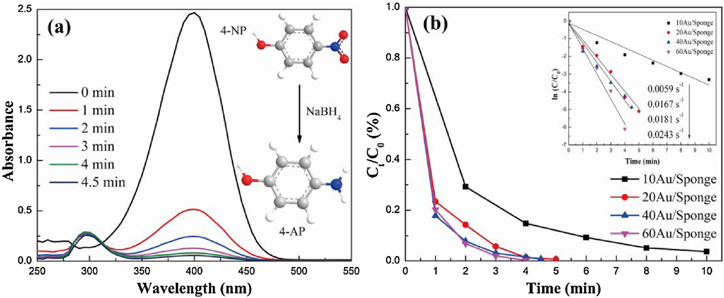
Similarly, we also tested the catalytic performance of the Au/PU sponge on the catalytic reduction of 4-NP. In this experiment, the yellow color of 4-NP/NaBH4 solution faded and bleached ultimately with the addition of the AuNP/Sponge catalyst. The fading time decreased with the increase of the AuNPs amount, and the effect of the AuNPs amount on the catalytic efficiency was then systematically investigated by using UV-Vis spectrophotometry (Fig. 5 and Fig. S7). The peak intensity at 400 nm decreased and the one at 295 nm increased gradually with the increase of time. Fig. S8 demonstrated the peak position shifted from 315 nm to 400 nm, when the NaBH4 was added into the 4-NP solution. The peak at 400 nm represented 4-NP and the peak at about 295 nm was attributed to 4-AP, as reported from other studies.[41, 42] Consequently, the change of peak intensity was triggered by the transformation from 4-NP to 4-AP, when the AuNP/Sponge catalyst was added into 4-NP/NaBH4 solutions.
Fig.5.
(a) UV-vis absorption spectra of 4-NP reduction over 40AuNP/Sponge catalyst, and (b) Ct/C0 vs. time plot.
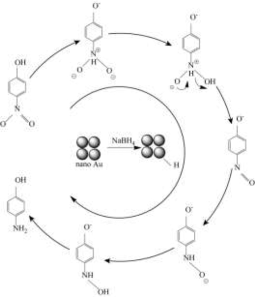
Fig. 5(b) displayed the 4-NP conversion by AuNP/Sponge with different AuNPs amounts. The conversion rate of 60AuNP/Sponge could reach 79.8% within 1 min and nearly 100.0% within 4 min. This conversion rate was satisfactory and higher than that of many studies.[43] As shown in Scheme 2, the transformation from 4-NP to 4-AP was a six electron process in the presence of NaBH4.[41] AuNPs on the PU sponge transferred NaBH4 to active hydrogen species adsorbed on the catalyst surface. Afterward, the nitro groups of 4-NP molecules presented in the interfacial region would be transferred to amino groups with the induction of adsorbed hydrogen species.[44] In addition, it was reported that the transformation from 4-NP to 4-AP was thermodynamically favorable but kinetically unfavorable without the catalyst.[41] In other words, AuNPs were the key active component and the AuNPs amount played an important role in the catalytic reduction reaction. As a consequence, the catalytic efficiency decreased gradually when the AuNPs amount reduced on the AuNP/Sponge catalyst. However, the conversion rate of the 40AuNP/Sponge catalyst could also reach 100.0% within 4.5 min, which was still excellent for catalytic reduction. Fig. 5(b) also displayed the first-order kinetic curves of 4-NP over AuNP/Sponge with different amounts of AuNPs. Similar to the result of 2-NA, it could be seen that the data points followed linearity as well, which was due to the excess NaBH4 in the reaction solution. The values of k were 0.0243, 0.0181, 0.0167, and 0.0059 s−1 for the 60AuNP/Sponge, 40AuNP/Sponge, 20AuNP/Sponge, and 10AuNP/Sponge, respectively. Considering that both the efficiency and economy were significant factors in practical application, the 40AuNP/Sponge was chosen as the optimum catalyst. Furthermore, we calculated the k value and made a comparison with reported values from previous studies (Table 1).[45–47] The k value of 40AuNP/Sponge was also higher than those of many solid-phase catalysts.
Scheme.2.
Proposed reaction mechanism of 4-NP transformation to 4-AP.
Table 1.
Catalytic efficiency comparison in 4-NP conversion
3.3. XRD analysis
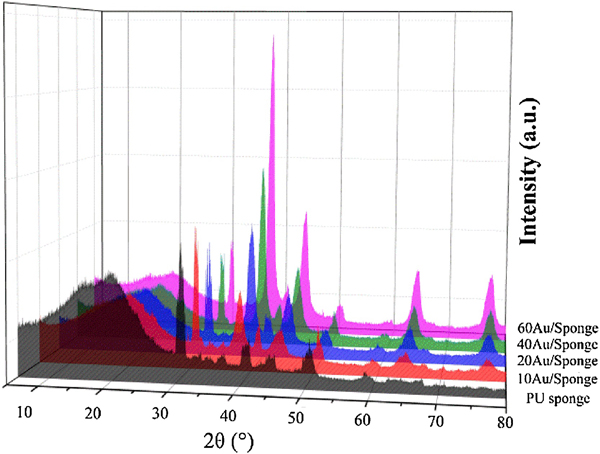
XRD patterns of PU sponge and AuNP/Sponge catalyst were analyzed and the results were demonstrated in Fig. 6 and Fig. S9. All the reflections of the samples provided the diffraction patterns for the CaMg(CO3)2 (PDF-ICDD 75–1656) and Au (PDF-ICDD 04–0784). The broad amorphous peak (spanned at 10–30 °) corresponded to the polyurethane in the sponge. As shown in Fig. 6 and Fig. S9, for the PU sponge, the three strong peaks at 2θ=30.96 °, 41.17 °, 51.09 ° were attributed to (104), (11–3) and (11–6) diffractions, respectively. It was suggested that the PU sponge consisted of the amorphous polyurethane and crystalline dolomite (the main component was CaMg(CO3)2). For the AuNP/Sponge catalyst, the obvious Bragg reflections of Au were observed and the three strong peaks at 2θ=38.25 °, 44.46 °, 77.72 ° were attributed to (111), (200) and (311) diffractions, respectively. The strongest peak intensity ratio of Au/CaMg(CO3)2 increased gradually because the relative amount of CaMg(CO3)2 decreased with the increase of the AuNPs amount. In addition, the diffraction peaks of CaMg(CO3)2 shifted to a higher-angle region, while Au peaks shifted to a lower-angle region, implying that the unit cell volume of Au swelled and that of CaMg(CO3)2 shrank with the increase of AuNPs amount. In other words, there was a strong interaction between AuNPs with CaMg(CO3)2. Furthermore, the peak intensity and half-peak width of CaMg(CO3)2 had no noticeable changes, implying that the structure of PU sponge did not change after the AuNPs preparation process, which was significant for the reuse and regeneration of the catalyst.
Fig.6.
X-ray diffraction patterns of different catalyst samples.
3.4. FT-IR analysis
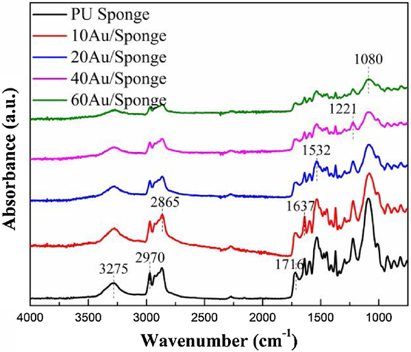
It is well accepted that polyurethane was capable of forming several kinds of hydrogen bonds due to the presence of a donor N-H group and a C=O acceptor group in the urethane linkage.[48] These bands have been widely used to characterize the presence of polyurethane. Fig. 7 showed FT-IR spectra of PU sponge and AuNP/Sponge catalyst (750–4000 cm−1), where both spectra were similar to each other and all the peaks were attributed to polyurethane. The band at 3275 cm−1 was assigned as -NH stretching in the urethane group and the band spanned at 2700–3000 cm−1 was assigned as the -CH stretching.[49] The band at 1716 cm−1 and at 1637 cm−1 (spanned at 1620–1750 cm−1) was assigned as the C=O stretching vibration (amide I). The band at 1532 cm−1 (spanned at 1500–1550 cm−1) was assigned as the amide II (C-N stretching and N-H bending).[50] The band at 1221 cm−1 (spanned at 1200–1250 cm−1) was assigned as the amide III (C-N stretching and N-H bending) and the band at 1080 cm−1 (spanned at 1000–1150 cm−1) was assigned as C-O-C asymmetric stretching.[51] In addition, all the bands decreased gradually, which was mainly due to the relative amount of polyurethane decreased with the increase of the AuNPs amount. However, there was no peak shift, suggesting that the AuNPs preparation process did not alter the original interactions among PU sponge. In other words, the structure of PU sponge had no change after the AuNPs preparation process, which was beneficial to maintain the catalytic efficiency after 5 recycling times.
Fig.7.
FT-IR spectra of different catalyst samples.
3.5. TGA analysis
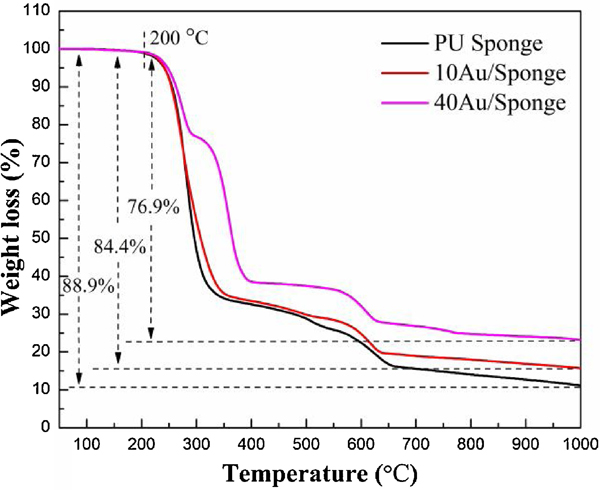
Fig. 8 and Fig. S10 displayed the TGA and DTG thermograms of PU sponge and Au/Sponge catalyst. From the literature, there were three basic mechanisms for the thermal degradation of the polyurethane: (1) urethane bond dissociation into basic components; (2) breaking of the urethane with the formation of primary amine; (3) splitting the urethane bond into secondary amine and carbon dioxide.[52] There was no weight loss when the temperature increased to 200 °C. It was due to the sample was dried before each test so that moisture was eliminated. All the samples had three stages of degradation: the first stage spanned at 200–400 °C; the second stage spanned at 400–550 °C and the third stage spanned at 550–700 °C. It could be speculated that the first stage degradation was led by the polyurethane phase, the second stage was resulted from a soft segment and the third stage was due to the CaMg(CO3)2.
Fig.8.
TGA thermograms of PU sponge and AuNP/Sponge catalysts.
The thermal stability could be expressed by the thermal index while the first and second stages of AuNP/Sponge needed a higher temperature for the degradation than that of PU sponge. In consequence, it could be speculated that the AuNP/Sponge catalyst had higher thermal stability than the PU sponge. The improvement in thermal stability can be attributed to the presence of strong interaction between the AuNPs with the PU sponge. The slight shift of the third stage may be resulted from the higher thermal conductivity of AuNPs than that of polyurethane. At last, the weight loss of PU sponge expanded to 88.9% while that of 10AuNP/Sponge and 40AuNP/Sponge increased to 84.4% and 76.9%, respectively. The difference was due to the existence of AuNPs in the PU sponge. Therefore, the amount of AuNPs in the PU sponge could be deduced by the difference of the weight loss and the contents of AuNPs in these three samples were 0%, 5%, and 14%, respectively. This suggested there was a loss of AuNPs during the process.
3.6. XPS analysis
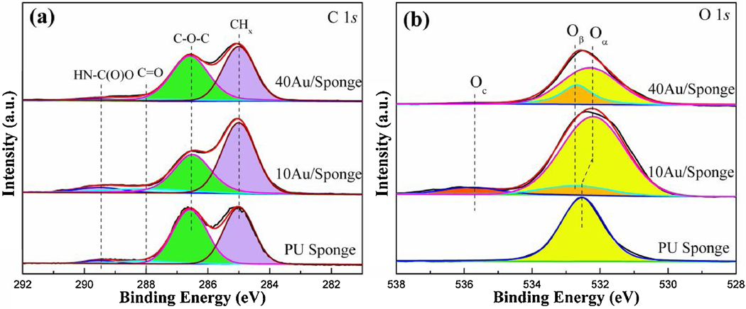
The surface composition and oxidation states of catalysts played an important role in the catalytic reduction reaction, so XPS was tested to investigate the surface properties of the catalysts. XPS analysis also further verified the formation of the AuNP/Sponge catalyst and the efficient removal of oxygenated functional groups of the catalysts. Fig. 9 and Fig. S11 demonstrated the survey, C 1s, O 1s and Au 4f XPS high-resolution spectra of PU sponge and AuNP/Sponge catalysts. From Fig. S11, it could be seen that the PU sponge mainly consisted of C and O elements. On the other hand, for the 10AuNP/Sponge and 40AuNP/Sponge catalysts, the strong doublet peaks of Au 4f emerging at 87.6 eV and 84.0 eV were attributed to Au0 4f5/2 and Au0 4f7/2, respectively.[53] There was also no other peak ascribed to Au3+, illustrating that the reduction of Au3+ to Au0 was complete during the catalyst preparation. In addition, some peaks attributed to Na element were observed in the AuNP/Sponge catalysts, which was resulted from the NaBH4 during the catalyst preparation. These observations revealed that Au0 was the predominant species in AuNP/Sponge catalyst.
Fig.9.
(a) C 1s and (b) O 1s XPS high-resolution scan spectra of PU sponge and AuNP/Sponge catalysts.
Fig. 9(a) showed the representative C 1s spectra for the PU sponge and AuNP/Sponge catalysts. All of them exhibited four peaks: (1) the peak located at 285.0 eV was the aliphatic carbon (CHx); (2) the peak located at 286.5 eV was ether (C-O-C); (3) the peak located at 288.0 eV was carbons bond to a single oxygen (C=O, carbonyl); (4) the peak located at 289.5 eV was carbons bond to two oxygen atoms (O-C=O, carbamide).[54] The intensity of the C-O-C peak decreased, which was consistent with reduced alcohol (C-OH) surface functionalization. It suggested that the AuNPs consumed the hydroxyl groups of PU sponge and formed strong interaction between AuNPs and the PU sponge. Fig. 9(b) demonstrated the O 1s spectra for the PU sponge and AuNP/Sponge catalysts. For the PU sponge, it was composed of a single broad peak centered at 532.5 eV (Oα). When the AuNPs were used to modify the PU sponge surface, a new peak attributed to C-OH surface groups was observed (Oβ). This new carbon and oxygen surface environment formed by the strong interaction between AuNPs and C-O-C groups. Moreover, the peak located at 535.8 eV may be attributed to the presence of adsorbed hydroxide (OH-, Oc).[55, 56] At last, there was a strong interaction between Au and O atoms so that the O 1s peaks of AuNP/Sponge showed a shift toward lower binding energy after the catalyst preparation. The strong interaction also guaranteed high reusability of the AuNP/Sponge catalyst.
Table 2 showed the atomic ratios of PU sponge and AuNP/Sponge catalysts. It could be seen that the AuNPs amount of 40AuNP/Sponge was higher than that of 10AuNP/Sponge. This trend was consistent with the TGA results. However, the AuNPs’ amount of XPS results was lower than that of TGA results. It suggested that more AuNPs have been generated in the sponge interior.
Table 2.
Atomic ratios of PU sponge and AuNP/Sponge surfaces.
| Sample | C (At.%) | O (At.%) | Au (At.%) |
|---|---|---|---|
| PU sponge | 72.69 | 27.31 | 0 |
| 10AuNP/Sponge | 61.86 | 35.28 | 2.86 |
| 40AuNP/Sponge | 69.48 | 27.46 | 3.06 |
3.7. SEM analysis
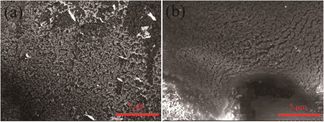
Fig. 10 demonstrated SEM micrographs of fresh and used 40AuNP/Sponge (used for 5 times) catalysts. As shown in Fig. 10(a) and Fig. S12, the fresh 40AuNP/Sponge consisted of nano polyurethane sponge and the sponge had loose structures. After the measurement, the diameter of the sponge was about 20–40 nm. The AuNPs grew along the surface of the polyurethane sponge. The structure of 40AuNP/Sponge became compact gradually and the AuNPs aggregated after 5 times of use. Comparing Fig. S12 with Fig. S13, it could be seen that the used catalyst was brighter than the fresh one, which was due to a small amount of AuNPs separated from the PU sponge during use so that the electrical conductivity of the sample became poorer. The aggregation of AuNPs and the separation of a small amount of AuNPs probably were the main reasons that the catalytic activity decreased gradually after repeated recycling times. Fortunately, the 40AuNP/Sponge still exhibited excellent catalytic performance after many recycling times.
Fig.10.
SEM micrograph of (a) fresh 40AuNP/Sponge and (b) used 40AuNP/Sponge catalysts.
4. Conclusions
In this work, an Au/PU sponge catalyst platform was fabricated via a facile one-step method for efficient catalysis with high reusability. The PU sponge and the AuNP/Sponge catalysts were structurally and morphologically characterized by XRD, TGA, SEM, FT-IR, and XPS, respectively. The AuNPs grew along the surface of polyurethane sponge evenly and the PU sponge consisted of nano polyurethane. The AuNP/Sponge platform exhibited excellent catalytic performance for transforming a nitro group into an amino group. The conversion rate of 2-NA reached nearly 100.0% within 1.5 min and 4-NP was catalytically reduced completely within 4.5 min by the 40AuNP/Sponge catalyst. Furthermore, the PU sponge could maintain its 3D structure during the AuNPs preparation process, and form a strong interaction with AuNPs, which enabled high reusability of the AuNP/Sponge catalyst. Therefore, this high-efficiency AuNP/Sponge catalyst platform with high reusability can have great potential for various practical environmental and other catalytic applications [57].
Supplementary Material
Highlights.
An Au/polyurethane (PU) sponge catalyst was prepared by a facile one-step method.
It exhibits both excellent catalytic performance and high reusability.
It is the first time to report PU sponge for catalytic reduction of nitroaromatics.
The strong interaction between AuNPs and PVA sponge enabled high reusability.
The nanocatalyst platform has wide environmental and other catalytic applications.
Acknowledgments:
We would like to acknowledge the financial support from the U.S. NSF-PREM program (DMR 1827745) and Philadelphia Foundation. We are also grateful to the financial support from the National Institute of Allergy and Infectious Disease of the NIH (R21AI107415), Postgraduate Research & Practice Innovation Program of Jiangsu Province (KYCX18_1078), and the Medical Center of the Americas Foundation.
Footnotes
Appendix A. Supplementary data:
Supplementary data associated with this article can be found, in the online version, at
Publisher's Disclaimer: This is a PDF file of an unedited manuscript that has been accepted for publication. As a service to our customers we are providing this early version of the manuscript. The manuscript will undergo copyediting, typesetting, and review of the resulting proof before it is published in its final form. Please note that during the production process errors may be discovered which could affect the content, and all legal disclaimers that apply to the journal pertain.
References:
- [1].Dou M, Garcia JM, Zhan S, Li X, Chem Comm 52 (2016) 3470–3473. [DOI] [PMC free article] [PubMed] [Google Scholar]
- [2].Wei X, Zhou W, Sanjay ST, Zhang J, Jin Q, Xu F, Dominguez DC, Li X, Anal Chem 90 (2018) 9888–9896. [DOI] [PMC free article] [PubMed] [Google Scholar]
- [3].Fu G, Sanjay ST, Zhou W, Brekken RA, Kirken RA, Li X, Analytical Chemistry 90 (2018) 5930–5937. [DOI] [PMC free article] [PubMed] [Google Scholar]
- [4].Zhan S, Zhang H, Zhang Y, Shi Q, Li Y, Li X, Appl. Catal. B: Environmental 203 (2017) 199–209. [DOI] [PMC free article] [PubMed] [Google Scholar]
- [5].Wong A, Lin Q, Griffin S, Nicholls A, Regalbute JR, Science 358 (2017) 1427–1430. [DOI] [PubMed] [Google Scholar]
- [6].Lopez-Tejedor D, Benavente R, Palomo JM, Catal. Sci. Technol. 8 (2018) 1754–1776. [Google Scholar]
- [7].Liu Y, Liu SL, Wang Y, Zhang QH, Gu L, Zhao SC, Xu DD, Li YF, Bao JC, Dai ZH, J. Am. Chem. Soc. 140 (2018) 2731–2734. [DOI] [PubMed] [Google Scholar]
- [8].Zhao GX, Liu HM, Ye JH, Nano Today 19 (2018) 108–125. [Google Scholar]
- [9].Sanjay ST, Zhou W, Dou M, Tavakoli H, Ma L, Xu F, Li X, Advanced Drug Delivery Reviews 128 (2018) 3–28. (*Five-Year impact factor 17.23). [DOI] [PMC free article] [PubMed] [Google Scholar]
- [10].Thomas M, Sheikh MUD, Ahirwar D, Bano M, Khan F, Colloid Interf J. Sci. 505 (2017) 115–129. [DOI] [PubMed] [Google Scholar]
- [11].Cirtiu CM, Dunlop-Brière AF, Moores A, Green Chem. 13 (2011) 288–291. [Google Scholar]
- [12].Rostamnia S, Doustkhah E, Karimi Z, Amini S, Luque R, ChemCatChem 7 (2015) 1678–1683. [Google Scholar]
- [13].Garcia P, Malacria M, Aubert C, Gandon V, Fensterbank L, ChemCatChem 2 (2010) 493–497. [Google Scholar]
- [14].Katla SK, Zhang J, Castro E, Bernal RA, Li XJ, ACS Appl. Mater. Inter. 10 (2018) 75–82. [DOI] [PMC free article] [PubMed] [Google Scholar]
- [15].Hashmi AS, Hutchings GJ, Angew Chem Int Ed Engl 45 (2006) 7896–7936. [DOI] [PubMed] [Google Scholar]
- [16].Yang M-Q, Pan X, Zhang N, Xu Y-J, CrystEngComm 15 (2013) 6819–6828. [Google Scholar]
- [17].An Q, Yu M, Zhang YT, Ma WF, Guo J, Wang CC, J. Phys. Chem. C 116 (2012) 22432–22440. [Google Scholar]
- [18].Wu Z, Jiang DE, Mann AK, Mullins DR, Qiao ZA, Allard LF, Zeng C, Jin R, Overbury SH, J. Am. Chem. Soc. 136 (2014) 6111–6122. [DOI] [PubMed] [Google Scholar]
- [19].Jiang HL, Liu B, Akita T, Haruta M, Sakurai H, Xu Q, J. Am. Chem. Soc. 131 (2009) 11302–11303. [DOI] [PubMed] [Google Scholar]
- [20].Corrie TJ, Ball LT, Russell CA, Lloyd-Jones GC, Journal of the American Chemical Society 139 (2017) 245–254. [DOI] [PubMed] [Google Scholar]
- [21].Han D, Bao Z, Xing H, Yang Y, Ren Q, Zhang Z, Nanoscale 9 (2017) 6026–6032. [DOI] [PubMed] [Google Scholar]
- [22].Kimura A, Hayama H, Hasegawa J.-y., Nageh H, Wang Y, Naga N, Nishida M, Nakano T, Polym. Chem. 8 (2017) 7406–7415. [Google Scholar]
- [23].Wang N, Li XF, Yang J, Shen YX, Qu J, Hong S, Yu ZZ, RSC Adv. 6 (2016) 88897–88903. [Google Scholar]
- [24].Yang XJ, Tian PF, Zhang CX, Deng YQ, Xu J, Gong JL, Han YF, Applied Catalysis B: Environmental 134–135 (2013) 145–152. [Google Scholar]
- [25].Yang XJ, Tian PF, Wang HL, Xu J, Han YF, Journal of Catalysis 336 (2016) 126–132. [Google Scholar]
- [26].Han YF, Phonthammachai N, Ramesh K, Zhong ZY, White T, Environmental Science & Technology 42 (2008) 908–912. [DOI] [PubMed] [Google Scholar]
- [27].Zeng T, Ziegelgruber KL, Chin YP, Arnold WA, Environ. Sci. Technol. 45 (2011) 6814–6822. [DOI] [PubMed] [Google Scholar]
- [28].Ullah N, Imran M, Liang K, Yuan CZ, Zeb A, Jiang N, Qazi UY, Sahar S, Xu AW, Nanoscale 9 (2017) 13800–13807. [DOI] [PubMed] [Google Scholar]
- [29].Li X, Wang X, Song S, Liu D, Zhang H, Chem.-Eur. J. 18 (2012) 7601–7607. [DOI] [PubMed] [Google Scholar]
- [30].Deka P, Deka RC, Bharali P, New J Chem 38 (2014) 1789. [Google Scholar]
- [31].Gupta VK, Yola ML, Eren T, Kartal F, Çağlayan MO, Atar N, J. Mol. Liq. 190 (2014) 133–138. [Google Scholar]
- [32].Lamey D, Beswick O, Cárdenas-Lizana F, Dyson PJ, Sulman E, Kiwi-Minsker L, Appl Catal A 542 (2017) 182–190. [Google Scholar]
- [33].Huong P-T, Lee B-K, Kim J, Lee C-H, Materials & Design 101 (2016) 210–217. [Google Scholar]
- [34].Zhang W, Wang G, He Z, Hou C, Zhang Q, Wang H, Li Y, Materials & Design 109 (2016) 492–502. [Google Scholar]
- [35].Guria MK, Majumdar M, Bhattacharyya M, J. Mol. Liq. 222 (2016) 549–557. [Google Scholar]
- [36].Yue YY, Liu HY, Yuan P, Yu CZ, Bao XJ, Sci. Rep. 5 (2015) 10. [DOI] [PMC free article] [PubMed] [Google Scholar]
- [37].Huang C, Ye W, Liu Q, Qiu X, ACS Appl. Mater. Inter. 6 (2014) 14469–14476. [DOI] [PubMed] [Google Scholar]
- [38].Sahiner N, Ozay H, Ozay O, Aktas N, Appl. Catal., A 385 (2010) 201–207. [Google Scholar]
- [39].Ahmad I, Kamal T, Khan SB, Asiri AM, Cellulose 23 (2016) 3577–3588. [Google Scholar]
- [40].Koga H, Namba N, Takahashi T, Nogi M, Nishina Y, ChemSusChem 10 (2017) 2560–2565. [DOI] [PMC free article] [PubMed] [Google Scholar]
- [41].Kamal T, Khan SB, Asiri AM, Environmental Pollution 218 (2016) 625–633. [DOI] [PubMed] [Google Scholar]
- [42].Zhang PH, Sui YM, Xiao GJ, Wang YN, Wang CZ, Liu BB, Zou GT, Zou B, J. Mater. Chem. A 1 (2013) 1632–1638. [Google Scholar]
- [43].Li J, Liu CY, Liu Y, Journal of Materials Chemistry 22 (2012) 8426. [Google Scholar]
- [44].Lv JJ, Wang AJ, Ma XH, Xiang RY, Chen JR, Feng JJ, Journal of Materials Chemistry A 3 (2015) 290–296. [Google Scholar]
- [45].Basavegowda N, Mishra K, Lee YR, Journal of Alloys and Compounds 701 (2017) 456–464. [Google Scholar]
- [46].Ren ZH, Li HT, Gao Q, Wang H, Han B, Xia KS, Zhou CG, Materials & Design 121 (2017) 167–175. [Google Scholar]
- [47].Mei LP, Wang R, Song P, Feng JJ, Wang ZG, Chen JR, Wang AJ, New J Chem 40 (2016) 2315–2320. [Google Scholar]
- [48].Bahadur A, Shoaib M, Saeed A, Iqbal S, E-Polymers 16 (2016) 463–474. [Google Scholar]
- [49].Zhang CL, Hu JL, Li X, Wu Y, Han JP, J. Phys. Chem. A 118 (2014) 12241–12255. [DOI] [PubMed] [Google Scholar]
- [50].Schuchardt P, Unger M, Siesler HW, Spectrochim. Acta. A 188 (2018) 478–482. [DOI] [PubMed] [Google Scholar]
- [51].Zhang CL, Hu JL, Wu Y, J. Mol. Struct. 1072 (2014) 13–19. [Google Scholar]
- [52].Oprea S, Oprea V, E-Polymers 16 (2016) 277–286. [Google Scholar]
- [53].More PM, Dongare MK, Umbarkar SB, Granger P, Dujardin C, Catal. Today 306 (2018) 23–31. [Google Scholar]
- [54].Watkins L, Bismarck A, Lee AF, Wilson D, Wilson K, Appl. Surf. Sci. 252 (2006) 8203–8211. [Google Scholar]
- [55].Rinsch CL, Chen X, Panchalingam V, Eberhart RC, Wang J-H, Timmons RB, Langmuir 12 (1996) 2995–3002. [Google Scholar]
- [56].Kelly JM, Short RD, Alexander MR, Polymer 44 (2003) 3173–3176. [Google Scholar]
- [57].Jin Q, Shen Y, Ma L, Pan Y, Zhu S, Zhang J, Zhou W, Wei X, Li X, Catalysis Today 327 (2019) 279–287. [DOI] [PMC free article] [PubMed] [Google Scholar]
Associated Data
This section collects any data citations, data availability statements, or supplementary materials included in this article.


