

Abstract
In the last decades many innovations have improved the hip replacement and the hip reconstruction surgery such as the introduction of the robotic-arm assisted surgery associated with the direct anterior approach (DAA). This surgical approach for total hip arthroplasty (THA) is growing in popularity and its effectiveness has been demonstrated to improve patients’ outcomes, especially regarding more accurate implant placement, less post operative pain, faster recovery and lower of prosthesis dislocation risk. The robotic-arm assisted surgery is another really great innovation for the orthopedic surgeons. It allows to create a patient-specific THA pre-operative planning and to perform a much more accurate surgical procedure. This article outlines authors’ surgical technique of performing accurate pre-operative planning and robotic-assisted THA using direct anterior approach based on the experience of 534 patients and to discuss details of this technique. (www.actabiomedica.it)
Keywords: total hip arthroplasty, robotic technology, direct anterior approach, Mako system, surgical technique
Introduction
Total hip arthroplasty (THA) is the surgical treatment of choice for patients with end-stage osteoarthritis that significantly reduces pain and improves hip function and quality of life.
Despite good functional outcomes achieved for the majority of patients, malpositioning of the components still remains the most biomechanical issue associated with this procedure, which can results in mechanical failures including component impingement, hip dislocation, leg length discrepancy, accelerated bearing surface wear with peri-prosthetic bone resorption, and altered hip biomechanical function. (1-4).
Over the years, robotic technology has been widespread used in the medical world, involving the orthopaedic specialty, particularly in the adult hip and knee reconstructive surgery. The robotic arm-assisted surgical system allows to make a patient’s specific pre-operative planning and to perform a robotic surgery based on a three-dimensional (3D) computed tomography (CT) models of the patient’s hip. This new surgical technique is innovative allowing to minimize the potential human errors, reducing the intra-operative complication rates (5).
In addition, there is a debate if the surgical approach might have an influence on implant successful outcome. The concept of minimal invasive approach is expressed not only to reduce the size of the incision, but also in less muscle damage and a better respect of the soft tissues. The use of the direct anterior approach (DAA) in total hip arthroplasty seems to gain popularity thanks to a careful respect of soft tissues using an anatomical inter-muscular approach (6). Thanks to this surgical approach, the patient might have a quicker recovery, a shorter hospitalization and can start with an earlier rehab program (7).
In recent studies, it has been shown that the DAA allows an improvement in clinical outcomes in the first 6 weeks, which seems to level out after that (8-11).
The purpose of this study is to describe the surgical technique in performing a robotic arm-assisted THA (Mako Robotic Arm assisted Total Hip™, Stryker, Warsaw, Indiana USA) using the DAA based on the experience of 534 patients and to discuss details of this technique.
Surgical technique
Pre-operative planning
Pre-operative CT scans of pelvis and both knees need to be obtained. Specific anatomical data are imported into a preoperative workstation to be evaluated creating a virtual planning and allowing the surgeon its execution. The MAKO® robotic arm-assisted system uses CT scan data to create a patient-specific pre-operative planning for proper component size selection and accurate intra-operative stem and cup positioning. Furthermore, 3D models of patients’ pelvis and knees provide informations about the native anatomy, including the pelvic tilt, leg length and hip offset (12).
This technology offers a virtual preoperative planning and the role of the robot is to assist the surgeon during the stem and cup placement and in the final check.
Surgical technique
Patient position: The patient, under spinal or general anesthesia, is positioned supine on a standard operating room table with a gel cushion under the buttock of the operative side.
The lower extremities are prepared separately using a bilateral sterile limb drapes, allowing for manual comparison of lengths intraoperatively and for stability testing. This drape completely covers the two legs leaving the anterior part of the iliac crest and the anterolateral region of the thigh on both side on view and protected by a sterile and transparent adhesive drape.
The surgeon requires an assistant and a theatre nurse. A third assistant is not essential. The presence of an experienced biomedical engineer during the pre-operative planning and surgery is nevertheless mandatory.
Positioning of the robotic system – Pre-operative planning: The robotic arm should be located on the operative side of the patient and aligned at the same level of the anterior superior iliac spine (ASIS). The approach angle between the robotic arm and the operating table should be about 45°. An infrared camera is positioned next to patient’s head and it can be moved intra-operatively. The computer screen showing in real time the operative planning is positioned in front of the surgeon whereas the biomedical engineer’s bench is in a corner of the operating room (Figure 1).
Figure 1.
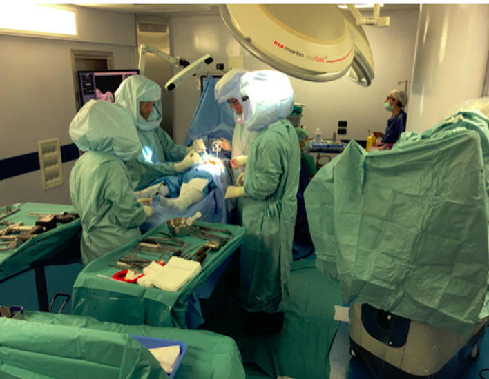
Author’s operating room: infrared camera at the head of the table, next to patient’s head, the computer screen in front of the surgeon and the biomedical engineer in the corner of the operating room
Every pre-operative planning is made using the “enhanced” procedure. The patient-specific pre-operative planning enables an accurate choice of the size and position of stem and cup prosthesis, thanks to a virtual 3D model of the patient’s joint that considers the new implant on three spatial dimensions. This allows to rebuild the articular geometry correctly and to know the combined version (CV), planned on the patient’s hip anatomical features. The CV value is calculated summing the stem and cup version. Knowledge of precise CV and center of rotation (COR) means to create a stable and well-balanced implant without any impingement between the components or muscular forces imbalances due to an incorrect muscle levers (13-16).
In the pre-operative step, the surgeon can modify the planning (size and position of the components) in order to optimize the offset values and the leg length (17) (Figure 2).
Figure 2.

The 3D preoperative model based on patient’s CT data. On panel A estimated hip length and combined offset are compared to opposite hip. On panel B the orientation and depth of the acetabular component in the transverse view of the hip joint are showed.
Surgical incision (the direct anterior approach): The use of the direct anterior approach with the robotic technique requires to slightly modify the direction of the classical surgical incision. In contrast to the manual technique, the incision should be more oblique and distal towards the thigh, allowing a reduction in muscle tension in order to have a better view and a comfortable working space to the anterior trochanteric region. In the meantime the assistant makes two small stab skin wounds with 11 blade, over the anterior edge of the contralateral iliac crest, about 1 cm apart from each other and 2 threaded pins are inserted into the thickest portion of iliac crest (they must protrude from the skin by about 10 cm). After the two pins have been fixed, the pelvic attachment device is inserted onto the pins. This allows a connection between the surgeon and the software through the infrared camera, during the acetabular registration phase.
The skin incision, on the affect side, starts 2 cm below and lateral to the anterior superior iliac spine (ASIS). It must be continued distally and laterally towards the greater trochanter region for about 10 cm, with an oblique course (the length of the incision can vary related to the dimension of the patient) (Figure 3).
Figure 3.

Planned incision of modified direct anterior approach.
Under the skin there is an adipose layer placed over the thin band of the tensor fasciae latae muscle. The fat tissue is taken out and the band is cut in the direction of the muscle fibers. The upper portion of the fascia is bluntly dissected from the muscular belly and using a finger is possible to release it and identify the intermuscular septum between the tensor fasciae latae muscle and the sartorius muscle. Deeply is well recognizable the anterior and proximal part of the rectus muscle and the “unnamed fascia”. The fascia must be cut in lengthwise and under it there is the vascular bundle originating from the lateral circumflex femoral artery. The vascular bundle must be tied up and cauterized otherwise it could be a bleeding source. Two retractors are placed around the greater trochanter respectively in the medial and lateral part of it and a third Homann fixed on the top of the acetabulum creating a wide working area. A C-shape capsulotomy is performed. It runs from lateral to medial side along the anterior edge of the acetabulum and encircling the femoral neck till the lesser trochanter. We don’t remove the capsule entirely because we consider it useful in protecting the medial vascular bundle and the nervous structures from the surgical tools. At the end of the surgery, if the condition of the capsule is good we could suture it.
Screws placement: Once the capsule has been opened the surgeon using a drill makes a hole on the anterolateral part of the greater trochanter and inserts two screws of different size. The smaller screw called “check point” needs to verify the accuracy of bone registration and a second larger screw used for holding the array required for connection with the infrared camera (Figure 4). Both screws are positioned close together and it is essential to check their stability. If they become loose, the accuracy and registration are not valid, and the measure of the leg length and offset values becomes inaccurate.
Figure 4.

A: schematic representation of acetabular and femoral checkpoint. B: trochanteric screw is showed
Femoral registration: In order to complete the femoral registration, the surgeon has to touch thirty two required points all around the anterior part of the femoral head and the proximal femur (from the femur neck to the lesser trochanter), as identified by the software and showed on the computer screen. The required points are took using a specific probe. This is an essential step in verifying the compliance with skeletal geometry. The registration must be done very precisely with a margin of error less than 0.5 mm (Figure 5), otherwise it will not be valid. Once kept all points and completed the registration, the cutting line of the femoral neck will be showed on the display and the surgeon will marked it on the bone with a bovie tip, following precisely the line on the screen (Figure 6).
Figure 5.

Surgeons map femoral checkpoint with a probe
Figure 6.

Resection neck level can be identified on computer screen
The osteotomy is performed using an oscillating saw. Once the neck is completely cut the femoral head is extracted carefully using a corkscrew device.
Femoral preparation: The femur is always prepared first. A correct exposure of the proximal femur is fundamental because it allows the surgeon to work comfortably avoiding complications, including canal perforation, calcar and greater trochanter fractures. Three retractors are placed around the trochanteric area after freeing the greater trochanter bone from the capsule. The first retractor is placed medially above the lesser trochanter, the second under the greater trochanter and the last one, a sharp retractor, is placed above the acetabulum in order to elevate the rectus femoris muscle and iliocapsularis muscle groups.
With the help of the assistant, the limb, initially in an extended position, should be gradually externally rotated and adducted. In the same time the first surgeon lifts the proximal femur up by a small hook previously inserted at the level of the osteotomy rim. The ischiofemoral ligament is exposed (Figure 7) and partially detached to release the apex of the greater trochanter from the posterior part of the acetabular rim (posterolateral release). A curved retractor is placed under the greater trochanter and applying a gentle force on it allows to expose completely the proximal femur.
Figure 7.

The ischiofemoral ligament consists of a triangular band of strong fibers on the posterior side of the hip joint
At this point the limb is placed in a figure-4 position under the contralateral leg by the assistant surgeon. It is advised to apply a pressure on the knee to further externally rotate the femur and facilitate the preparation with the dedicated broaches. When the femoral release is particularly difficult, the piriformis tendon, which is often retracted in long-standing osteoarthritis, can be released in order to avoid a fracture of the greater trochanter.
Femoral version registration: During the femoral preparation, it is important to pay attention to the first broach position, it must be in line with the femoral canal. The correct enter point is at the bottom and slightly posteromedial side of the greater trochanter (Figure 8). Removing part of the cortical bone in the central part of the trochanter recommended to allow an easier approach to the canal.
Figure 8.

A and B: two different views of femoral neck resection
The femoral canal is prepared using sequentially increasing size broaches. Concerning the rotation of the rasp, it should be chosen based on the native femoral version (NFV, the angle between the axis of the femoral neck and the epicondylar axis of the knee), as detected on the preoperative 3D CT scans. Once the femur has been done, the definitive broach will be leave in place and the surgeon will insert on its top a trial neck that has three small holes (two on its base and one on its top). With the probe, the three points will be touched to measure (in millimetres) the femoral version, the off-set and leg length. In choosing the femoral version, it is mandatory to consider the native femoral canal anatomy in order to obtain proper alignment and a correct stem fixation.
Acetabular registration: Before starting with the acetabular registration, a pelvic check point is inserted outside the acetabulum cavity, just above its superior rim (the check point is essential to give spatial anatomical information to the software). Thirty-two points placed into the cavity and all around the acetabulum edge are taken using the probe. The surgeon touches precisely all the points displayed on the computer screen. An error of more than 0,5 mm is not accepted and thus the required points must be retaken again.
The preoperative position of the cup (inclination and anteversion) is planned based on the stem version value (SV) recorded before during the femoral version registration (18, 19). The software advices a CV range for the male and female patients (25°-35° men and 30°-50° women) (13, 20).
Acetabular reaming and cup implantation: Before starting to map the acetabulum area, the surgeon must take out the soft tissues present all around the rim and inside the cavity. Osteophytes should not be removed to avoid altering the bone registration. First, three landmarks are kept as indicated by the software and subsequently carrying on with the sequence of 32 points scattered around and inside the cavity. Once the request points have been recorded, osteophytes can be removed. Now the surgeon, using the robotic arm is ready to ream the acetabulum cavity. The reaming is done using the planned socket plus one size more (1 mm) to achieve the final right size. During this step the reamer remains constrained to the plan so it cannot go out of bounds in the superior, medial and anterior-posterior directions. The reaming is line to line and is very precise. The surgeon must keep doing with the reaming until all the COR numbers on display are zero and the colour of the reamed area on the digital screen becomes green. This confirm that the process is completed, and the correct depth and the acetabular centre of rotation planned is reached. If the surgeon tries to ream 1 mm over the robotic arm it will turn off. Once this step is over the final cup (Trident PSL HA™, Stryker, Warsaw, Indiana USA) is loaded onto the robotic arm and it is inserted into the acetabular area. A haptic tunnel keeps the planned version and inclination and prevents the surgeon going off-line or too deep. Every step is followed on the computer screen. The cup is implanted into the acetabulum by hitting the impactor with a mallet. The final position cup is checked with a probe in terms of its inclination and anteversion. This control is done by touching five points on the cup edge implanted and displayed on the screen (there is a tolerance, compared to the parameters planned of 2 degrees, which can be considered “physiological”). Once the check has done a standard plastic liner is inserted into the cup.
Leg length discrepancy and stability: The definitive femoral stem (Accolade II ™, Stryker, Warsaw, Indiana USA) is inserted into the canal manually and fully seat with a specific instrument. Once cleaned and dried the neck taper, a trial head is placed onto the taper. The hip is reduced, and the femoral array is placed into the femoral screw so the surgeon can check range of motion, prosthesis stability, leg length and offset values indicated on the software screen. The hip stability and the leg length are two priorities which must be adjusted in case of excess or defect length in order to get a hip biomechanically correctly working. Once the balance is found, the computer will communicate the final values on the screen. A few millimeters of leg-length discrepancy could be physiological, and the procedure should be considered over.
The surgeon must pay attention when the operative limb is initially longer than the contralateral one. In these cases, it is better to avoid increasing the initial leg-length discrepancy or, if possible, to reduce it, preferably using a dual mobility head to guarantee a greater implant stability.
All arrays, screws and check points are removed. The definitive head is placed onto the taper. Pulse lavage is done in the surgical site, the hip is reduced, and subcutaneous tissues are given closing by layer.
Discussion
Performing a successful hip prosthesis implant requires an accurate pre-operative planning, choosing prosthetic components suitable for the specific clinical case and a correctly performed surgical procedure. These are three conditions that allow to regain the physiological range of motion, to restore the periarticular muscle balance and to correct any leg length discrepancy.
Restoring a biomechanically balanced hip prosthesis should enable less stress on the implanted components and a great stability and durability.
Orthopedic surgeons’ attention and interest in robotic surgery has recently increased thanks to the promising clinical outcomes recorded on the field. This technique allows to abolish conventional pre-operative planning with templates, decreasing round-off error. Pre-operative digital planning does not be linked exclusively to the surgeon’s practical experience, but it depends upon a pre-operative patient-specific procedure (21).
Robotic technique combined to direct anterior approach can be considered an excellent combination, able to give patients a quicker and satisfactory post-surgical recovery.
The pre-operative planning includes 3D CT scan of the pelvis and the both knee joints, according to the established protocol.
In order to create a specific planning, it is important to identify femoral and acetabular morphological features, to detect osteophytic areas and the presence of cystic bone lesions or necrotic bone areas. In the pre-operatively step the surgeon studies the planning shown by the software through a 3D graphical display. The robotic software provides several data such as the final size of the prosthetic components, skeletal spatial orientation, inclination and version of acetabular cup and femoral stem. These data must always be compared with the contralateral hip and correct them in case of anatomical discrepancy.
It is essential to know the values of the femoral version and the inclination/version of the acetabular cup in order to establish the optimal combined version.
Using the traditional surgical technique these data are not available because not measurable. For these reasons, the surgeon might have in his hands a system that allows him to perform a stable and biomechanically balanced prosthetic implant, limiting mechanical failures due to components impingement and hip dislocation.
The Mako™ protocol provides a pre-established range values relating to the combined version adapted to gender (25°-35° for men and 30°-50° for women) and to the version and inclination of the acetabular cup (version 20°, inclination 40°). These ranges remain the same for any preferred surgical approach.
Data such as prosthetics version, off-set, leg length are editable during surgery depending on anatomical hip features and surgeon’s decisions.
At the beginning of the experience with DAA, the surgeon is inclined to respect the Mako™ range advised. However, improving surgical skills, surgeons may get away from this range, creating a personalized “Combined Version range”, based upon intra operative findings and functional outcomes. The decision to slightly modify the protocol ranges raises because intra-operatively an impingement between femoral prosthetic neck and acetabular cup during hip rotation is sometimes observed, with a decreased range of motion. Modifying these parameters can be a great choice because it avoids a prosthetic dislocation but also to use liner with antidislocation shoulder anymore.
In order to verify this potential improvement, the combined version data (pre and postoperatively) in 534 patients operated by computer-arm assisted THA with DAA between November 2016 and March 2020 were furtherly analyzed.
Being aware of the risk of anterior dislocation using DAA, the values of the combined version by varying the acetabular cup version before considering the version of the femoral stem were intentionally modified. The hypothesis was that the version of femoral stem should be close to zero degree and consequently the acetabular cup anteversion could be reduced.
As regards the femoral stem orientation, the target is to achieve a value close to zero (neutral position) if the femur is originally retroverted, otherwise if the femur is anteverted it is advised to reduce the femoral anteversion respecting the physiological limits (5°-20° using Paley classification) (22). A recent multicenter study has been published, involving three orthopaedic centers working with the robotic system. A huge variability of the human native femoral version is reported (23). In this study, between 2012 and 2016, 362 patients underwent THA using the Mako™ robotic system. The collected data about the native femoral version confirm this wide variability ranging from –22° to +49°. Only with a robotic system it is possible to analyse the relationship between the acetabulum and the pelvis avoiding the surgeon to make mistakes for the inaccurate information of hip anatomy.
In the early phase of our experience with Mako™ system, we used the anterolateral approach, and the values of combined version were different (30°-32°). In 2016, shifting the approach to DAA and considering functional outcomes, we reduced combined version to 24°-26°.
Therefore, combined version is related to the surgical approach. In direct anterior approach CV should be 23.36° +/- 4.58°, in posterolateral approach CV should be 37.59° +/- 4.62° while using anterolateral approach CV should be 28.55° +/- 6.91° (23, 24, 25, 26, 27). These values show significant differences attributable to the surgical approach and to hip’s morphological features.
Recording our data, native femoral version presented variability range from -18° to 36°. After reaming and stem implant, we register values in a range between 0 and 2 degrees.
For the acetabular cup mean inclination was 40°/42° and acetabular anteversion was 16°-32°. The final average of CV ranged effectively from 22°to 28°.
Differences of final off-set compared to the preoperatively values were between -3 and +4 mm, while leg-length discrepancy values were between -2 and +3 mm. Following planned values, over 95% of cases had a final femoral head with neutral length and 36 mm of diameter. Mean inclination of femoral neck was 127°.
In patients with a stiff lumbosacral hinge or lumbar vertebral arthrodesis, it must be considered that the pelvic tilt is absent (change from sitting to standing position). In this case a lesser cup anteversion must be planned in order to increase the anterior coverage of the femoral head.
Conclusion
In the last decades many innovations have improved the hip replacement and reconstruction surgery. The modern prosthetic designs and new materials guarantee durability. To improve the survival of the implants, it should be necessary to eliminate the outliers that should influenced the surgeons’ technical accomplishment. Furthermore, it is also necessary to consider the limits of human performance especially when a mechanical operation is done in a biological contest.
The robotic guide navigation could be the right solution to improve the outcomes because it provides reproducible and predictable results and it can be useful for the surgeon in his performance.
By robotic navigation and using a patient’s specific pre-operative planning it is allowed to plan the correct combined anteversion of the stem and cup, to have a correct hip center of rotation and to restore the physiological off set and leg length. This is extremely important to avoid complications and early mechanical failures like hip impingement, dislocation or muscle imbalance.
Finally, the system is safe for acetabular preparation and cup implantation.
In the choice of a surgical approach it is important to consider and respect the ranges values of the combined version, fundamental in order to obtain a stable joint.
Robotic-arm-assisted surgery can be considered to potentially improve hip joint biomechanics being a valuable innovation for total hip arthroplasty.
Conflict of interest:
Authors declare that they have no commercial associations (e.g. consultancies, stock ownership, equity interest, patent/licensing arrangement etc.) that might pose a conflict of interest in connection with the submitted article.
References
- 1.Bozic KJ, Kurtz SM, Lau E, Ong K, Vail TP, Berry DJ. The epidemiology of revision total hip arthroplasty in the United States. J Bone Joint Surg Am. 2009;91:128e33. doi: 10.2106/JBJS.H.00155. https://doi.org/10.2106/JBJS.H.00155 . [DOI] [PubMed] [Google Scholar]
- 2.Kroell A, Beaule P, Krismer M, et al. Aseptic stem loosening in primary THA: migration analysis of cemented and cementless fixation. Int Orthop. 2009;33:1501–1505. doi: 10.1007/s00264-008-0701-1. https://doi.org/10.1007/s00264-008-0701-1. [DOI] [PMC free article] [PubMed] [Google Scholar]
- 3.Anakwe RE, Jenkins PJ, Moran M. Predicting dissatisfaction after total hip arthroplasty: a study of 850 patients. J Arthroplasty. 2011;26(2):209–13. doi: 10.1016/j.arth.2010.03.013. https://doi.org/10.1016/j.arth.2010.03.013. [DOI] [PubMed] [Google Scholar]
- 4.Lee YK, Yoo JJ, Koo KH, et al. Metal neck and liner impingement in ceramic bearing total hip arthroplasty. J Orthop Res. 2011;29:218–222. doi: 10.1002/jor.21246. https://doi.org/10.1002/jor.21246. [DOI] [PubMed] [Google Scholar]
- 5.Jewett BA, Collis DK. High complication rate with anterior total hip arthroplasties on a fracture table. Clin Orthop Relat Res. 2011;469(2):503–7. doi: 10.1007/s11999-010-1568-1. doi: 10.1007/s11999-010-1568-1. [DOI] [PMC free article] [PubMed] [Google Scholar]
- 6.Light TR, Keggi KJ. Anterior approach to hip arthroplasty. Clin Orthop Relat Res. 1980;152:255–60. [PubMed] [Google Scholar]
- 7.Poehling-Monaghan KL, Kamath AF, Taunton MJ, Pagnano MW. Direct anterior versus miniposterior THA with the same advanced perioperative protocols: surprising early clinical results. Clin Orthop Relat Res. 2015;473(2):623–31. doi: 10.1007/s11999-014-3827-z. doi: 10.1007/s11999-014-3827-z. [DOI] [PMC free article] [PubMed] [Google Scholar]
- 8.Rodriguez JA, Deshmukh AJ, Rathod PA, Greiz ML, Deshmane PP, Hepinstall MS, Ranawat AS. Does the direct anterior approach in THA offer faster rehabilitation and comparable safety to the posterior approach. Clin Orthop Relat Res. 2014;472(2):455–63. doi: 10.1007/s11999-013-3231-0. doi: 10.1007/s11999-013-3231-0. [DOI] [PMC free article] [PubMed] [Google Scholar]
- 9.Seng BE, Berend KR, Ajluni AF, Lombardi AV., Jr Anterior-supine minimally invasive total hip arthroplasty: defining the learning curve. Orthop Clin North Am. 2009;40(3):343–50. doi: 10.1016/j.ocl.2009.01.002. doi: 10.1016/j.ocl.2009.01.002. [DOI] [PubMed] [Google Scholar]
- 10.Spaans AJ, van den Hout JA, Bolder SB. High complication rate in the early experience of minimally invasive total hip arthroplasty by the direct anterior approach. Acta Orthop. 2012 Aug;83(4):342–6. doi: 10.3109/17453674.2012.711701. doi: 10.3109/17453674.2012.711701. [DOI] [PMC free article] [PubMed] [Google Scholar]
- 11.Zawadsky MW, Paulus MC, Murray PJ, Johansen MA. Early outcome comparison between the direct anterior approach and the mini-incision posterior approach for primary total hip arthroplasty: 150 consecutive cases. J Arthroplasty. 2014;29(6):1256–60. doi: 10.1016/j.arth.2013.11.013. doi: 10.1016/j.arth.2013.11.013. [DOI] [PubMed] [Google Scholar]
- 12.Domb BG, El Bitar YF, Sadik AY, et al. Comparison of robotic-assisted and conventional acetabular cup placement in THA: a matched-pair controlled study. Clin Orthop Relat Res. 2014;472(1):329–36. doi: 10.1007/s11999-013-3253-7. doi: 10.1007/s11999-013-3253-7. [DOI] [PMC free article] [PubMed] [Google Scholar]
- 13.Dorr LD, Malik A, Dastane M, Wan Z. Combined anteversion technique for total hip arthroplasty. Clin Orthop Relat Res. 2009;467(1):119–27. doi: 10.1007/s11999-008-0598-4. doi: 10.1007/s11999-008-0598-4. [DOI] [PMC free article] [PubMed] [Google Scholar]
- 14.Bargar WL, Jamali AA, Nejad AH. Femoral anteversion in THA and its lack of correlation with native acetabular anteversion. Clin Orthop Relat Res. 2010;468(2):527–32. doi: 10.1007/s11999-009-1040-2. doi: 10.1007/s11999-009-1040-2. [DOI] [PMC free article] [PubMed] [Google Scholar]
- 15.Imai H, Miyawaki J, Kamada T, Takeba J, Mashima N, Miura H. Preoperative planning and postoperative evaluation of total hip arthroplasty that takes combined anteversion. Eur J Orthop Surg Traumatol. 2016;26:493–500. doi: 10.1007/s00590-016-1777-8. doi: 10.1007/s00590-016-1777-8. [DOI] [PMC free article] [PubMed] [Google Scholar]
- 16.Widmer KH, Zurfluh B. Compliant positioning of total hip components for optimal range of motion. J Orthop Res. 2004;22(4):815–21. doi: 10.1016/j.orthres.2003.11.001. doi: 10.1016/j.orthres.2003.11.001. [DOI] [PubMed] [Google Scholar]
- 17.Hirata M, Nakashima Y, Hara D, Kanazawa M, Kohno Y, Yoshimoto K, et al. Optimal anterior femoral offset for functional range of motion in total hip arthroplastya - a computer simulation study. Int Orthop. 2015;39(4):645–51. doi: 10.1007/s00264-014-2538-0. doi: 10.1007/s00264-014-2538-0. [DOI] [PubMed] [Google Scholar]
- 18.Abdel MP, von Roth P, Jennings MT, Hanssen AD, Pagnano MW. What safe zone? The vast majority of dislocated THAs are within the Lewinnek safe zone for acetabular component position. Clin Orthop Relat Res. 2016;474(2):386–91. doi: 10.1007/s11999-015-4432-5. doi: 10.1007/s11999-015-4432-5. [DOI] [PMC free article] [PubMed] [Google Scholar]
- 19.Barrack RL. Dislocation after total hip arthroplasty: implant design and orientation. J Am Acad Orthop Surg. 2003;11(2):89–99. doi: 10.5435/00124635-200303000-00003. doi: 10.5435/00124635-200303000-00003. [DOI] [PubMed] [Google Scholar]
- 20.Dorr LD, Wan Z, Malik A, Zhu J, Dastane M, Deshmane P. A comparison of surgeon estimation and computed tomographic measurement of femoral component anteversion in cementless total hip arthroplasty. J Bone Joint Surg. 2009;91(11):2598–604. doi: 10.2106/JBJS.H.01225. doi: 10.2106/JBJS.H.01225. [DOI] [PubMed] [Google Scholar]
- 21.Elson L, Dounchis J, Illgen R, et al. Precision of acetabular cup placement in robotic integrated total hip arthroplasty. Hip Int Hip Int. 2015;25(6):531–6. doi: 10.5301/hipint.5000289. doi: 10.5301/hipint.5000289. [DOI] [PubMed] [Google Scholar]
- 22.Paley D. Berlin Heidelberg: Springer; 2002. Principles of deformity correction. [Google Scholar]
- 23.Marcovigi A, Ciampalini L, Perazzini Caldora P, Grandi G, Catani F. Evaluation of Native Femoral Neck Version and Final Stem Version Variability in Patients With Osteoarthritis Undergoing Robotically Implanted Total Hip Arthroplasty. J Arthroplasty. 2019;34(1):108–115. doi: 10.1016/j.arth.2018.06.027. doi: 10.1016/j.arth.2018.06.027. [DOI] [PubMed] [Google Scholar]
- 24.Kiernan S, Hermann KL, Wagner P, Ryd L, Flivik G. The importance of adequate stem anteversion for rotational stability in cemented total hip replacement. Bone Joint J. 2013;95-B(1):23–30. doi: 10.1302/0301-620X.95B1.30055. doi: 10.1302/0301-620X.95B1.30055. [DOI] [PubMed] [Google Scholar]
- 25.Herrlin K, Pettersson H, Selvik G, Lidgren L. Femoral anteversion and restricted range of motion in total hip prostheses. Acta Radio. 1988;29(5):551–3. [PubMed] [Google Scholar]
- 26.Yoshimine F. The safe-zones for combined cup and neck anteversions that fulfill the essential range of motion and their optimum combination in total hip replacements. J Biomech. 2006;39(7):1315–23. doi: 10.1016/j.jbiomech.2005.03.008. doi: 10.1016/j.jbiomech.2005.03.008. [DOI] [PubMed] [Google Scholar]
- 27.Patel AB, Wagle RR, Usrey MM, Thompson MT, Incavo SJ, Noble PC. Guidelines for implant placement to minimize impingement during activities of daily living after total hip arthroplasty. J Arthroplasty. 2010;25(8):1275–81.e1. doi: 10.1016/j.arth.2009.10.007. doi: 10.1016/j.arth.2009.10.007. [DOI] [PubMed] [Google Scholar]