Abstract
BACKGROUND AND PURPOSE:
New deep brain stimulation leads with electrode contacts that are split along their circumference allow steering of the electrical field in a predefined direction. However, imaging-assisted directional stimulation requires detailed knowledge of the exact orientation of the electrode array. The purpose of this study was to evaluate whether this information can be obtained by rotational 3D fluoroscopy.
MATERIALS AND METHODS:
Two directional leads were inserted into a 3D-printed plaster skull filled with gelatin. The torsion of the lead tip versus the lead at the burr-hole level was investigated. Then, 3 blinded raters evaluated 12 3D fluoroscopies with random lead orientations. They determined the lead orientation considering the x-ray marker only and considering the overlap of the gaps between the contact segments. Intraclass correlation coefficients and an extended version of the Bland-Altman plot were used to determine interrater reliability and agreement of the measurements of the different raters.
RESULTS:
Electrode torsion of up to 35° could be demonstrated. Evaluation of the lead rotation considering the x-ray marker only revealed limits of agreement of ±9.37° and an intraclass correlation coefficient of 0.9975. In addition, taking into account the lines resulting from overlapping of the gaps between the electrode segments, the limits of agreement to the mean were ±2.44° and an intraclass correlation coefficient of 0.9998.
CONCLUSIONS:
In directional deep brain stimulation systems, rotational 3D fluoroscopy combined with the described evaluation method allows for determining the exact orientation of the leads, enabling the full potential of imaging-assisted personalized programming.
Deep brain stimulation (DBS) is an established treatment for movement disorders (eg, Parkinson disease, tremor, and dystonia), drug-resistant epilepsy, and obsessive-compulsive disorder (for which DBS is still regarded experimental).1–4 The spectrum of indications is currently increasing: Several psychiatric indications are under investigation, including major depression, addiction, Alzheimer disease and dementias, eating disorders, Gilles de la Tourette syndrome, and schizophrenia. Although the stimulation technology stems from the 1970s and has seen little development, the therapeutic window of DBS can be limited by side effects that are caused by inadvertent co-stimulation of structures in the proximity of the targeted regions. Typically, DBS electrodes contained cylindrical contacts. Their activation resulted in roughly spherical stimulation fields around the surface of the contacts, which represent the volume of activated tissue. The potential advantages of current steering between contacts or in defined directions have been anticipated for many years.5 Recently, DBS electrode leads with electrode contacts that are split into 3 parts along the circumference of the electrode became available.6,7 Distributing the stimulation among these electrode segments allows steering of the electrical field in a predefined direction. In the subthalamic nucleus, DBS by this approach theoretically allows one to steer the field away from the internal capsule while at the same time allowing a better coverage of the nucleus and relevant pathways (eg, hyperdirect pathway), with a possibly better therapeutic window. Advanced imaging with individualized visualization of target structures is increasingly being used for personalized and direct stimulation planning.8–11 However, imaging-assisted directional stimulation requires detailed knowledge of the exact orientation of the electrode array with respect to its functional environment. The exact orientation of the segmented leads has to be determined by postoperative imaging because the degree of rotation varies during implantation and fixation of the electrode. Therefore, directional electrodes contain an x-ray marker. However, presently, no imaging technique has been described that sufficiently allows the exact determination of the degree of a possible lead rotation:
Anteroposterior and lateral x-rays allow only a rough estimation of the lead orientation depending on the angle between the marker and the image plane.
In a CT scan, the marker generates a large artifact. Under defined, but, however, unrealistic conditions in clinical practice (ie, leads parallel to scanner axis), this artifact could be used to estimate the lead orientation.
MR imaging is no option because, for now, the available directional DBS systems are not MR-imaging compatible.
We here investigated whether 3D fluoroscopy could serve as the imaging technique of choice to determine the exact degree of lead rotation and orientation of an implanted electrode array.
Materials and Methods
Experimental Setup
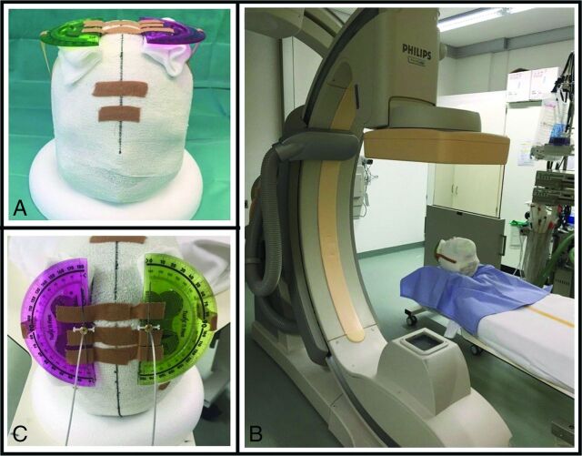
A 3D-printed plaster skull was filled with gelatin. Two burr-holes were drilled at the typical location for DBS electrode implantation and 2 directional electrodes (Model DB-2202-30; Boston Scientific, Natick, Massachusetts) were inserted. At the entry site of the electrodes, a marker was attached in the same orientation as the fluoroscopy marker at the electrode tip, and the electrodes were guided through protractors (Fig 1A, -C), which allow for determining the rotation of each electrode between 0° and 360°. (Fig 1B shows the setup in the 3D rotational fluoroscopy). We defined the lead orientation with the marker oriented exactly anteriorly as 0°, counting up to 360° with clockwise lead rotation when looking at the lead from above the skull.
Fig 1.
Two directional leads inserted in a 3D-printed plaster head filled with gelatin. At the entry site of the electrodes, a marker was attached in the same orientation as the x-ray marker at the electrode tip. The electrodes were guided through protractors (A,C), which allows for determining the rotation of each electrode between 0° and 360°(C, both oriented at 0°). Figure 1B shows the setup in the 3D rotational fluoroscopy.
Test for Electrode Torsion
To evaluate whether torsion of the electrodes that leads to a difference between orientation of the marker at the burr-hole and the marker at the electrode tip occurs, 1 3D fluoroscopy was obtained after electrode implantation, 1 after rotation of the electrodes 360° clockwise, and 1 after rotation of the electrodes counterclockwise. The orientation of the electrode markers was determined on the 3D fluoroscopy images.
Image Acquisition
In total, 12 3D fluoroscopy rotation scans were obtained via a flat panel detector C-arm system (Allura Xper FD20; Philips Healthcare, Best, the Netherlands). During a −120° to +120° rotation of the C-arm around the phantom, 120 frames were acquired. The rotation time was 4 seconds, and a standard “3D cerebral” protocol was used. The registered dose-area product was 2.327 mGy × cm2. The flat panel detector system provided a spatial resolution of 0.37 mm.
Determining the Electrode Rotation
A list of 24 random numbers between 1 and 360 was generated (Excel; Microsoft, Redmond, Washington), and the 2 electrodes were rotated for each 3D fluoroscopy according to this list.
Three blinded raters (1 neuroradiologist and 2 neurosurgeons) evaluated the lead rotation on a DICOM Viewer (Philips DICOM Viewer, Version R3.0 SP3; Philips Healthcare). First, they were asked to identify the image in the 3D rotational fluoroscopy where the plaster model with 1 metal marker attached to the inion and 1 to the nasion was depicted exactly in anteroposterior orientation. Then, they used 2 different methods to determine the lead rotation.
Method Using the Marker at the Electrode Tip
The first evaluation was based exclusively on the rotation of the marker at the electrode tip. Each rater evaluated the orientation of the 2 electrodes in the phantom for each of the 12 rotational angiography series. The raters were asked to determine the image with the marker exactly facing to the left side of the screen, facing the rater, and facing to the right side of the screen. The lead orientations were calculated accordingly, and the median values were compared. The agreement of the measurements of the raters was determined by using an extended version of the Bland-Altman plot12 to accommodate multiple observers proposed by Jones et al.13
The “Iron Sights” Method
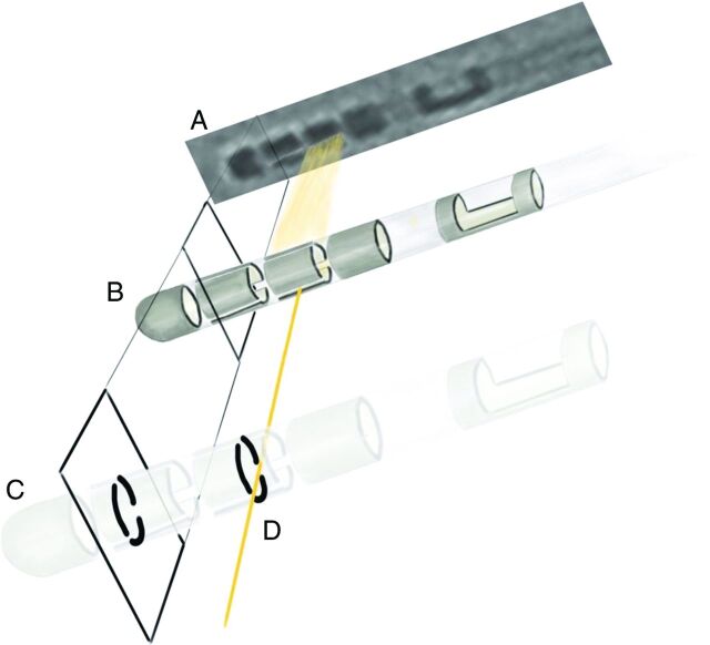
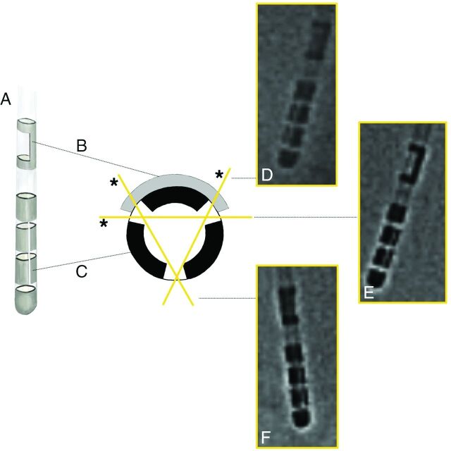
Two of the 4 contacts at the tip of the directional leads are split into 3 parts along the circumference of the electrode. When rotating the fluoroscopy around the head model with implanted electrodes, the gaps between these segments overlap in defined angles of view, resulting in a visible line. At lead orientations of exactly 30°, 90°, 150°, 210°, 270°, and 330°, these overlapping gaps can be detected because, at these angles, they align like iron sights in a weapon when aiming at a target (Figs 2 and 3).
Fig 2.
The gaps between the electrode segments can be considered as “iron sights.” They overlap when looking at the electrode from defined perspectives, resulting in a visible line (A). This line is seen only when the fluoroscopy beam (D) hits the electrode from exactly 1 these perspectives (B, C) and allows a precise definition of the electrode orientation.
Fig 3.
The directional lead (A) contains an x-ray marker (B) and segmented electrodes. The marker alone does not allow determining the exact lateral or anteroposter perspective. The gaps between the electrode segments overlap only when looking at the electrode from defined perspectives (D*, 30°, E, 90°, F, 150°, D, 210°, E*, 270°, and F*, 330°), resulting in a visible line.
The raters were asked to determine the 2 lateral angles of view (looking at the lead from 90° and 270°) and 2 more oblique angles of view (30°, 150°, 210°, or 330°). The lead orientations were calculated accordingly, and the median values were compared. The agreement of the measurements of the raters was determined by using an extended version of the Bland-Altman plot12 to accommodate multiple observers proposed by Jones et al.13
Sample Size
Sample size estimation for the comparison of 2 rater reliabilities or agreement has hardly been investigated to date. A rule of thumb was proposed by Fleiss14 by using 15–20 samples in reliability studies. Julious15 found that a sample size of 12 in pilot studies seems reasonable for the generation of pilot data. Given a continuous outcome, increasing the sample size beyond 12 samples per group did not have a profound influence on the confidence interval. Because there was no prior knowledge about the range of reliability, 12 samples with 2 electrodes each, and thus, 24 in total, were investigated.
Statistical Analysis
A random sample of 3 raters was chosen. Every rater measured each of the 24 orientations independently by using 2 different procedures of measurement (marker measurement and “iron sights” measurement). To assess the interrater reliability of the continuous measurements, intraclass correlation coefficients based on 2-way random-effects models were calculated.16 The 95% confidence intervals of the 2 intraclass correlation coefficients were compared. In addition, an extended version of the Bland-Altman plot12 to accommodate multiple observers, as proposed by Jones et al,13 was used to determine agreement of the measurements of different raters. Limits of agreement to the mean of the 3 measurements were calculated for each of the measurements. The limits of agreement were compared descriptively. All analyses were performed by using STATA/IC 12.1 (StataCorp, College Station, Texas).
Results
Electrode Torsion
The orientation of the electrode tip after straight implantation of the lead was +3.8° for the right electrode and +5.4° for the left electrode evaluated when applying the iron sights method. After 360° rotation clockwise, the right electrode tip was oriented at −5.5° and the left at +5.4°. After the rotation of −360° the electrode tips were oriented at +35.0° (right electrode) and +16.0° (left electrode).
Determining the Electrode Rotation
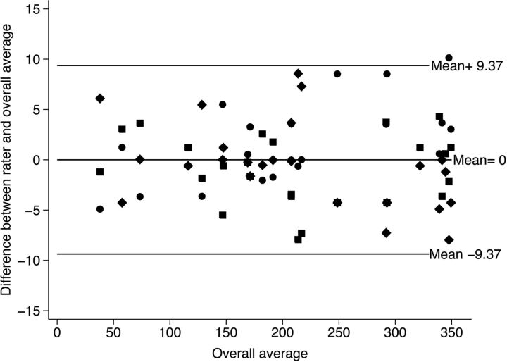
Each rater determined the degree of rotation of the electrode tip for the 2 electrodes in each of the 12 rotational angiography series. The first evaluation was based exclusively on the rotation of the marker. The results and the agreement of the measurements of the raters are shown in Fig 4.
Fig 4.
The 3 raters determined the lead orientations for each of the 12 rotational angiography series and 2 electrodes, considering only the x-ray marker. The extended version of the Bland-Altman plot12 to accommodate multiple observers proposed by Jones et al13 shows the mean difference between the raters and the overall average versus the overall average. The rotation could be defined between limits of agreement of ±9.37°.
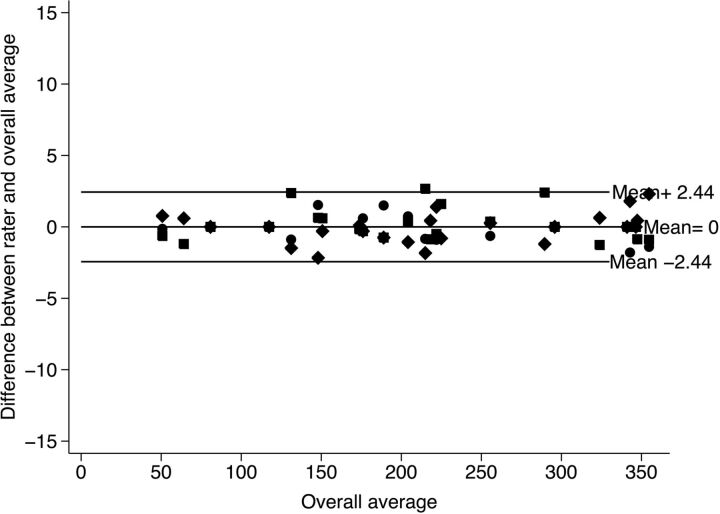
The second evaluation, using the iron sights method, was based on determining the perspectives in which the gaps between the directional electrode segments overlap. Lead orientations were calculated for these perspectives, and the median values were compared. The results and the agreement of the measurements of the raters are shown in Fig 5.
Fig 5.
Mean difference between the raters and the overall average versus the overall average of the results applying the “iron sights” method. The rotation could be defined between limits of agreement of ±2.44°.
Statistical Analysis
Both procedures of measurement showed a very high interrater reliability. The marker measurement had an intraclass correlation coefficient of 0.9975 (CI, 0.9951–0.9988). The iron sights measurement resulted in an intraclass correlation coefficient of 0.9998 (CI, 0.9997–0.9999). These high values might be the result of the wide range of observational values. Still, the confidence intervals for the 2 intraclass correlation coefficients are not overlapping, indicating a considerable difference between the 2 procedures of measurement.
To additionally assess the agreement of the raters, adjusted Bland-Altman plots were produced. The limits of agreement to the mean (of the 3 raters) for the marker measurement are ±9.37° (ie, 95% of the measurements are in the range of ±9.37° deviation of the mean of the 3 measurements). For the iron sights method, the limits of agreement are ±2.44°. The agreement for the iron sights methods is thus higher because the range of deviation is ±7° smaller than for the marker method.
Discussion
The availability of directional leads offers new possibilities for DBS therapy. Instead of the previous limitation (to apply only spherical stimulation fields around the surface of cylindrical contacts), the configuration of segmented electrodes now allows one to steer the electrical field in a predefined direction. If anatomic structures in the proximity of the lead limit the stimulation of the target region, the possibility to steer the field away from this structure can increase the therapeutic window. The full potential of this new technology includes visualization of anatomic structures responsible for effects and side effects and imaging-assisted personalized programming of the DBS system. DBS programming software integrating this feature is becoming available (eg, the GUIDE System [Boston Scientific]). This new technology requires the knowledge of the exact degree of rotation for each individual electrode to fully exploit these possibilities. One solution would be an exact orientation in a defined direction for all implanted electrodes (eg, 0°). Unfortunately, during the operation, the rotation of the lead cannot be exactly predicted because of several factors. The lead can turn during fixation and when securing the cable under the skin. Correction of the lead rotation by marking the direction of the contact segments at the level of the burr-hole and turning the electrode there does not lead to reliable results, as demonstrated by our test for electrode torsion: electrode rotation (+360° and −360°) resulted in a deviation of −5.5°, +5.4, +35.0°, and +16.0° from the expected orientation (0°) in the rotational 3D fluoroscopies. Therefore, an imaging technique that reliably allows for determining the lead orientation is needed, but has not been described so far. Anteroposterior and lateral x-rays depict the marker only from 2 perspectives, allowing only a rough estimation of the electrode rotation. In CT, the marker generates a large artifact. Bokil et al17 have investigated in vitro whether the CT signature of the electrode could be used to determine the orientation of the lead. They scanned with 0.6-mm section thickness and 50% overlap. When orienting the lead parallel to the scanner axis, they could determine the rotation with a mean accuracy of less than 3°. However, this setting is not realistic in clinical practice. With the leads oriented in physiologically plausible orientations relative to the scanner axis, the mean accuracy was described as less then 10°. They do not describe the dose of this CT.
Rotational 3D fluoroscopy is typically used to depict aneurysms. Delavallée et al18 described the application of 3D fluoroscopy for intraoperative control of the positioning of nondirectional DBS leads (Lead 3389; Medtronic, Minneapolis, Minnesota) in 10 patients by image fusion with the preoperative MR imaging scans. This imaging method can also display the marker of directional leads from multiple perspectives. We assumed that determining the best anteroposterior and lateral images of the marker should allow for defining the exact lead orientation. However, during evaluation of the different perspectives of the marker, configured as a C, we found that it is difficult to determine the exact lateral or anteroposterior perspective. The ideal markers should have features like iron sights in a gun, overlapping only when aiming exactly at the target. The gaps between the electrode segments have exactly this feature. They overlap when looking at the electrode from defined perspectives (30°, 90°, 150°, 210°, 270°, and 330°), resulting in a visible line. This line is seen only when the fluoroscopy beam hits the electrode from exactly 1 of the mentioned perspectives and allows a clearer definition of the electrode orientation than looking at the surface of the contacts. In combination with the torsion of the electrodes demonstrated in our first test, this iron sight method gives us a better ground truth than the electrode orientation defined at the protractor at the burr-hole. We hypothesized that if this method is as exact as we assume, there should be a very high interrater reliability. This is supported by the results of our investigation. The limits of agreement were ±2.44°. When using the marker alone to determine the lead orientation, the mean difference between the raters and the overall mean was ±9.37°. The interrater reliability was very high in both methods (the iron sights measurement resulted in an intraclass correlation coefficient of 0.9998 [CI, 0.9997–0.9999]). The marker measurement had an intraclass correlation coefficient of 0.9975 (CI, 0.9951–0.9988). But still, a significant difference was observed.
The limits of agreement only describe the agreement between the raters and do not provide information on the agreement to the true orientation of the electrode. Because the true orientation is unknown and no criterion standard measurement is available, a comparison of the agreement of the 2 measurements would not provide information on the accuracy of the measurements, either. Analyzing the properties of the 2 measurements by using rater reliability and agreement therefore provides helpful information to compare the quality and reproducibility of the measurements. For these criteria, significant differences could be found.
The only disadvantage is the radiation dose to the patient. The dose-area product of the 3D 240° rotational fluoroscopy used in our setup was 2.327 mGy × cm2, which is comparable with 4 standard skull x-rays with 600 mGy × cm2 per x-ray (reference values according to Bundesamt für Strahlenschutz). Regarding the effective dose of a head CT, which is approximately 2.3 mSv, the effective dose of a 3D 210° rotational scan with only 0.2 mSv is comparatively low.19 Because a head CT is an accepted standard diagnostic procedure, the usage of a 3D 210° rotational fluoroscopy scan for providing the required information on each individual DBS electrode rotation, and producing approximately one-tenth of the effective head CT radiation dose, is more than acceptable. Nevertheless, by optimizing the scan parameters, this already low effective radiation dose of the 3D rotational fluoroscopy scan may be decreased even further.
Conclusions
We could demonstrate that rotational 3D fluoroscopy can obtain the information needed to determine the orientation of the directional leads. However, the built-in marker, configured as a C (Fig 3B), does not allow for defining the exact lateral or anteroposterior perspective. Using this marker, the rotation could be defined between limits of agreement of ±9.37°. When using the overlapping gaps between the contacts at defined angles of view like iron sights, the degree of electrode rotation could be determined between limits of agreement of ±2.44°. No other available imaging technique after DBS surgery with directional electrodes (eg, CT and plain x-ray) can determine the electrode orientation in such accuracy. Therefore, rotational 3D fluoroscopy combined with the described (iron sights) evaluation is, in our opinion, the postoperative imaging of choice to enable the full potential of imaging-assisted personalized programming of the directional DBS system.
Acknowledgments
The scientific work of this study has received no industry funding or other third-party support.
ABBREVIATION:
- DBS
deep brain stimulation
Footnotes
Disclosures: Peter C. Reinacher—UNRELATED: Grants/Grants Pending: German Ministry for Economic Affairs and Energy*; Travel/Accommodations/Meeting Expenses Unrelated to Activities Listed: Boston Scientific, BrainLab.* Volker A. Coenen—UNRELATED: Grants/Grants Pending: Investigator-initiated trial support, Comments: Ongoing IITs with Boston Scientific and Medtronic (limited funding)*; OTHER: Clinical collaborative project with BrainLab AG, Comments, clinical collaborative project on the Elements software package for evaluation purposes; postdoc position is funded over 3 years. *Money paid to the institution.
References
- 1. Deep-Brain Stimulation for Parkinson's Disease Study Group. Deep-brain stimulation of the subthalamic nucleus or the pars interna of the globus pallidus in Parkinson's disease. N Engl J Med 2001;345:956–63 10.1056/NEJMoa000827 [DOI] [PubMed] [Google Scholar]
- 2. Deuschl G, Schade-Brittinger C, Krack P, et al. A randomized trial of deep-brain stimulation for Parkinson's disease. N Engl J Med 2006;355:896–908 10.1056/NEJMoa060281 [DOI] [PubMed] [Google Scholar]
- 3. Benabid AL, Pollak P, Gao D, et al. Chronic electrical stimulation of the ventralis intermedius nucleus of the thalamus as a treatment of movement disorders. J Neurosurg 1996;84:203–14 10.3171/jns.1996.84.2.0203 [DOI] [PubMed] [Google Scholar]
- 4. Vidailhet M, Vercueil L, Houeto JL, et al. Bilateral deep-brain stimulation of the globus pallidus in primary generalized dystonia. N Engl J Med 2005;352:459–67 10.1056/NEJMoa042187 [DOI] [PubMed] [Google Scholar]
- 5. Butson CR, McIntyre CC. Current steering to control the volume of tissue activated during deep brain stimulation. Brain Stimulat 2008;1:7–15 10.1016/j.brs.2007.08.004 [DOI] [PMC free article] [PubMed] [Google Scholar]
- 6. Pollo C, Kaelin-Lang A, Oertel MF, et al. Directional deep brain stimulation: an intraoperative double-blind pilot study. Brain J Neurol 2014;137:2015–26 10.1093/brain/awu102 [DOI] [PubMed] [Google Scholar]
- 7. Steigerwald F, Müller L, Johannes S, et al. Directional deep brain stimulation of the subthalamic nucleus: a pilot study using a novel neurostimulation device. Mov Disord Off J Mov Disord Soc 2016;31:1240–43 10.1002/mds.26669 [DOI] [PMC free article] [PubMed] [Google Scholar]
- 8. Coenen VA, Rijntjes M, Prokop T, et al. One-pass deep brain stimulation of dentato-rubro-thalamic tract and subthalamic nucleus for tremor-dominant or equivalent type Parkinson's disease. Acta Neurochir (Wien) 2016;158:773–81 10.1007/s00701-016-2725-4 [DOI] [PMC free article] [PubMed] [Google Scholar]
- 9. Schlaepfer TE, Bewernick BH, Kayser S, et al. Rapid effects of deep brain stimulation for treatment-resistant major depression. Biol Psychiatry 2013;73:1204–12 10.1016/j.biopsych.2013.01.034 [DOI] [PubMed] [Google Scholar]
- 10. Coenen VA, Allert N, Mädler B. A role of diffusion tensor imaging fiber tracking in deep brain stimulation surgery: DBS of the dentato-rubro-thalamic tract (drt) for the treatment of therapy-refractory tremor. Acta Neurochir (Wien) 2011;153:1579–85, discussion 1585 [DOI] [PubMed] [Google Scholar]
- 11. Coenen VA, Allert N, Paus S, et al. Modulation of the cerebello-thalamo-cortical network in thalamic deep brain stimulation for tremor: a diffusion tensor imaging study. Neurosurgery 2014;75:657–69, discussion 669–70 [DOI] [PubMed] [Google Scholar]
- 12. Bland JM, Altman DG. Statistical methods for assessing agreement between two methods of clinical measurement. Lancet 1986;1:307–10 10.1016/s0140-6736(86)90837-8 [DOI] [PubMed] [Google Scholar]
- 13. Jones M, Dobson A, O'Brian S. A graphical method for assessing agreement with the mean between multiple observers using continuous measures. Int J Epidemiol 2011;40:1308–13 10.1093/ije/dyr109 [DOI] [PubMed] [Google Scholar]
- 14. Fleiss JL. The Design and Analysis of Clinical Experiments. New York: Wiley; 1986 [Google Scholar]
- 15. Julious SA. Sample size of 12 per group rule of thumb for a pilot study. Pharm Stat 2005;4:287–91 10.1002/pst.185 [DOI] [Google Scholar]
- 16. Shrout PE, Fleiss JL. Intraclass correlations: uses in assessing rater reliability. Psychol Bull 1979;86:420–28 10.1037/0033-2909.86.2.420 [DOI] [PubMed] [Google Scholar]
- 17. Bokil H, Dorman D, Velasco R. Determining the orientation of directional deep brain stimulation leads from computed tomography data. Poster presented at: WSSFN Interim meeting, Mumbai, India. September 3–6, 2015. http://www.epostersonline.com/wssfn2015/node/126. Accessed March 6, 2017. [Google Scholar]
- 18. Delavallée M, Delaunois J, Ruwet J, et al. STN DBS for Parkinson's disease: results from a series of ten consecutive patients implanted under general anaesthesia with intraoperative use of 3D fluoroscopy to control lead placement. Acta Neurochir (Wien) 2016;158:1783–88 10.1007/s00701-016-2889-y [DOI] [PubMed] [Google Scholar]
- 19. Bridcut RR, Murphy E, Workman A, et al. Patient dose from 3D rotational neurovascular studies. Br J Radiol 2007;80:362–66 10.1259/bjr/95349672 [DOI] [PubMed] [Google Scholar]


