Abstract
BACKGROUND AND PURPOSE:
Quantitative data from DSA have become important tools for understanding hemodynamic changes of intracranial lesions. In this study, we evaluated 8 hemodynamic parameters in patients before and after carotid artery angioplasty.
MATERIALS AND METHODS:
DSA images of 34 patients with carotid stenosis who underwent angioplasty and stent placement were retrospectively analyzed. Eleven ROIs (M1, M2, A1, A2, the parietal vein, superior sagittal sinus, internal jugular vein, and 4 in the ICA) were selected on color-coded DSA. Eight hemodynamic parameters (bolus arrival time, TTP, relative TTP, full width at half maximum, wash-in slope, washout slope, maximum enhancement, and area under the curve) were measured from the time-concentration curves of these ROIs. The dependent t test for paired samples was applied to these parameters before and after stent placement.
RESULTS:
We found that the treatment significantly reduced TTP, relative TTP, bolus arrival time, and washout slope at all arterial ROIs and full width at half maximum and area under the curve at some arterial ROIs. Bolus arrival time was significantly reduced after treatment for all arterial ROIs, the parietal vein, and the superior sagittal sinus. The maximum enhancement and wash-in slope did not show significant changes after treatment. After treatment, the relative TTP from the ICA to M1, M2, and the parietal vein returned to normal values.
CONCLUSIONS:
In addition to TTP and relative TTP, other parameters can be used to evaluate peritherapeutic cerebral hemodynamic changes. Bolus arrival time has the potential to evaluate brain circulation at arterial and venous sites, especially when TTP cannot be measured because of an incomplete time-concentration curve.
Digital subtraction angiography has been the criterion standard for diagnosing cerebral vascular disease since 1970s. DSA imaging demonstrates the intravascular changes of concentration in the time domain and can be used as a surrogate marker for cerebral hemodynamics. Time-concentration curve analysis is the most commonly used approach because the results are easily accessible and intuitive for interventional purposes. Time-to-peak (also called time-to-maximum in some previous publications) is the most commonly used parameter. It is applied to detect intra-aneurysmal flow, and larger aneurysms demonstrate more prolonged TTP than smaller aneurysms.1 The difference in TTP between the parietal vein and cavernous ICA has been used to monitor cerebral hemodynamic changes to improve patient safety.2 Detecting shorter TTPs in carotid cavernous fistulas helps determine whether the venous outlets contain higher blood flow, which deserves treatment priority.3 In control angiography, normalization of blood flow indicates spontaneous latent obliteration.4 Other applications include monitoring angioplasty for vasospasm after subarachnoid hemorrhage5 and quantitatively grading Moyamoya disease.2
The standard gray-scale images of DSA are first encoded into a single composite color image according to the contrast bolus arrival time (BAT) at each point in the circulatory system of the brain. This single composite color image improves the speed of manual delineation of AVMs and makes the angioarchitecture and the flow characteristics of aneurysms, AVMs, fistulas, stenosis, occlusions, dissections, and tumors easier to understand.6 The color-coding of DSA was also developed by calculation of the maximal enhancement (ME) and the TTP of the time-concentration curve of each pixel.7 It improves the conspicuity of findings on DSA images of cerebral vascular lesions and helps with the visualization of fistula angioarchitecture and venous drainage patterns in patients with carotid cavernous fistulas.7 In addition, it facilitates real-time hemodynamic monitoring, helps determine the end point of embolization, and increases patient safety in the treatment of carotid cavernous fistulas.8,9
For carotid stenosis, the TTP or relative TTP (rTTP) of color-coded quantitative DSA has been used to evaluate cerebral circulation time and peritherapeutic hemodynamic changes in the intracranial circulation.3 rTTP was found to be a definitive alternative method of measuring cerebral circulation.10 Maximal slope and full width at half maximum (FWHM) are found to complement rTTP in the evaluation of cerebral circulation.10 Furthermore, the area under the curve (AUC) of the proximal common carotid arteries can be calculated from the time-concentration curves of color-coded DSA. A good correlation was found between the AUC and the relative CBV obtained from flat panel detector CT by injecting contrast medium into the ascending aorta.11 In this study, we evaluated 8 parameters obtained from color-coded quantitative DSA to understand the hemodynamic changes before and after stent placement in patients with carotid stenosis.
Materials and Methods
DSA images of 34 patients (mean age, 72.3 years; 27 men and 7 women) who underwent carotid angioplasty and stent placement were collected for retrospective analysis. The patients had unilateral carotid stenosis of >70%, according to the NASCET criteria. The DSA images were acquired on a clinical scanner (Artis zee; Siemens, Erlangen, Germany) with a frame rate of 6 frames/s for 9∼12 seconds. The image size was 1440 × 1440 pixels, the FOV was 22 cm, and the pixel size was 0.154 × 0.154 mm2. A power injector (Liebel-Flarsheim Angiomat; Illumina, San Diego, California) was used to inject the contrast bolus in the common carotid artery at the C4 vertebral body level, by using a 4F angiocatheter. A bolus of 12 mL of 60% diluted contrast medium (340 mg I/mL) was administered in 1.5 seconds. The injection catheter was placed at the same place in the pre- and postintervention acquisitions. The injection was synchronized with the start of the image acquisition. The scanning protocol was the same in the 2 sets of images obtained before and after stent placement. This retrospective study was approved by the institutional review board.
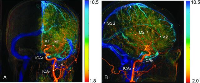
Image postprocessing was performed on a personal computer by using software programs written in Matlab (MathWorks, Natick, Massachusetts). In our Matlab program, the TTP and ME values of the time-concentration curve for each pixel were used to generate color-coded DSA images (Fig 1). The first image obtained in each view of the angiograms was defined as time = 0 for the TTP calculation. The color spectrum was used to represent TTP values, with a hot color (red) assigned to small TTP values and a cold color (blue) assigned to large TTP values. The ME was used to assign the brightness of these colors.
Fig 1.
Color-coded DSA images in the PA (A) and lateral (B) views. Eleven ROIs are manually selected for quantification of perfusion parameters. ICA1 on the PA view and ICA1 on lateral view are planned to be at the same place.
Eleven ROIs were selected for comparing hemodynamic parameters. The ROI was composed of 3 × 3 pixels with an area of 0.462 × 0.462 mm2. On the posterior-anterior (PA) view, we selected 5 ROIs: the internal carotid artery in 2 locations (ICA1 and ICA2) and the A1, M1, and internal jugular vein. On the lateral view, we selected 6 ROIs: ICA1, ICA2 (at middle of cavernous segment of the ICA), the A2, M2, parietal vein (PV), and the superior sagittal sinus (SSS). The PA view of ICA1 and the lateral view of ICA1 were selected at the same place in the upper neck because they were easily and consistently identified in the respective views. The locations of these ROIs are shown in Fig 1.
The time-concentration curves of the selected ROIs were fitted to a gamma-variate function described by
where K is a constant, t0 is the contrast arrival time of the fitted curve, and α and β are related to the wash-in and washout phases of the curve, respectively.12 The trust-region-reflective algorithm was used in the Matlab curve-fitting subroutine.13,14 An example is shown in Fig 2. The concentration is represented in arbitrary units.
Fig 2.
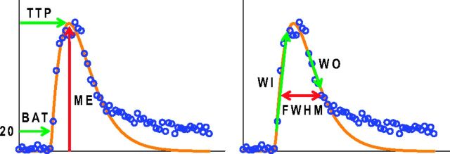
The measured (blue open circle) and fitted (orange line) time-concentration curves. Hemodynamic parameters such as maximum enhancement, time to peak, bolus arrival time, wash-in slope, washout slope, and full width at half maximum are all derived from the fitted curve.
According to the literature, the fitted t0 does not reliably represent the BAT.15 We calculated the BAT by using the first time point with a concentration higher than 20 arbitrary units. To evaluate the wash-in and washout of the contrast media, we fitted 4 consecutive temporal data points of Cγ(t) to a straight line described by
by using a least squares technique.16 The largest and smallest m-values were recorded to represent the wash-in slope (WI) and washout slope (WO), respectively. The ME, TTP, full width at half maximum, and the area under the curve of the fitted curve were measured to depict the curve.
The hemodynamic parameters, ME, TTP, BAT, FWHM, WI, WO, and AUC, measured on the ROIs before and after the stent placement treatment, were evaluated. The dependent t test for paired samples described by
was applied to the measured hemodynamic parameters before and after treatment, where XM and XSD were the mean and SD of the difference in a hemodynamic parameter measured before and after stent placement treatment, μ0 = 0, and n is the number of measurements.
Results
The anterior cerebral artery may not appear on the angiogram before stent placement because of insufficient blood flow. We measured the A1 in 18 cases and the A2 in 17 cases because their ROIs could be identified both before and after treatment on their color-coded images. All identified arterial ROIs, including the ICAs, M1, M2, A1, and A2, in these cases were successfully evaluated with all 8 parameters.
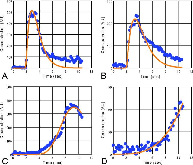
Figure 3 shows measured and fitted time-concentration curves of representative ROIs. Before stent placement, the MEs of the identified SSS in 16 patients and the internal jugular vein in 28 patients were found from the last image in their time-concentration curves (eg, Fig 3D). Assuming that the TTP occurred at the last time point was not correct. Therefore, TTP, rTTP, ME, FWHM, WO, and AUC of the SSS and internal jugular vein were listed as not measurable in Table 1. Furthermore, the FWHM, WO, or AUC was not measurable or not reliable for some ROIs in the PV and some other veins because of early termination in the washout phase (eg, Fig 3C). Only the BAT could be evaluated in all ROIs.
Fig 3.
Measured (blue circle) and fitted (orange line) time-concentration curves of representative ROIs before the stent-placement treatment: ICA2 (A), M2 (B), PV (C), SSS (D). Note that the time-concentration curve of the PV (C) lacks the middle and lower descending portion. The ME in the time-concentration curve of the SSS (D) is at the last temporal point. AU indicates arbitrary unit.
Table 1:
P values of all hemodynamic parameters before and after stenting at each ROIa
| ROI Locations | PA View |
Lateral View |
|||||||||
|---|---|---|---|---|---|---|---|---|---|---|---|
| ICA1 | ICA2 | M1 | A1 | IJV | ICA1 | ICA2 | M2 | A2 | PV | SSS | |
| ME | .27 | .11 | .15 | .79 | NA | .68 | .99 | .20 | * | .55 | NA |
| TTP | * | * | * | * | NA | * | * | * | * | * | NA |
| rTTP | – | *b | *b | *b | NA | – | *c | *d | *d | *d | NA |
| BAT | * | * | * | * | .32 | * | * | * | * | * | * |
| FWHM | * | * | * | .08 | NA | * | * | * | * | NA | NA |
| WI | .97 | .88 | .09 | .64 | .15 | .37 | .20 | .12 | .06 | .20 | NA |
| WO | * | * | * | * | NA | * | * | * | * | NA | NA |
| AUC | * | * | .06 | .39 | NA | * | * | * | .83 | NA | NA |
Note:—NA indicates not available because of incomplete data; –, not calculated; *, significant difference before and after stenting (P < .05); IJV, internal jugular vein.
TTP relative to ICA1 in the PA view.
TTP relative to ICA1 in the lateral view.
TTP relative to ICA2 in the lateral view.
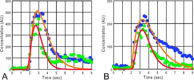
Figure 4 demonstrates the measured and fitted time-concentration curves for ROIs at the ICA2 and M2 in the lateral view, obtained before and after the stent-placement procedure. In this case, the contrast media arrived at these arteries at similar times, but they flushed out faster after the stent placement was performed. As a result of the faster washout of the contrast media, the FWHM and WO for these arteries decreased significantly after stent placement.
Fig 4.
A comparison of the time-concentration curves before and after the stent placement treatment for the ICA2 (A) and M2 (B) in the lateral view. The blue solid circles are measured data, and orange lines are the fitted curves before the treatment. The green solid circles and red lines are measured data and fitted curves, respectively, after treatment. AU indicates arbitrary unit.
Table 1 is a list of comparisons of the hemodynamic parameters before and after stent placement at different ROIs. According to Table 1, TTP and BAT showed significant differences before and after stent placement in 9 and 10 ROIs, respectively. The TTP, BAT, and WO showed significant changes before and after stent placement at all arterial ROIs and FWHM for most arterial ROIs. Among the venous ROIs measured, significant changes in TTP were found at the PV, and significant changes in the BAT were found at the PV and SSS. The ME and WI had no value in demonstrating the hemodynamic changes before and after stent placement. The P values of many of the venous ROIs were not available because their time-concentration curves did not reach a maximum or lacked a sufficient downward curve.
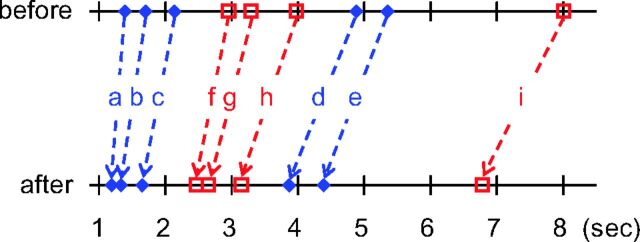
The statistical data for hemodynamic parameters with significant changes are shown in the PA (Table 2) and lateral (Table 3) views. For the TTP calculation, the first image was defined as time = 0. The rTTP value represents the time difference from an upstream vessel to a downstream one. After the stent-placement procedure, there was a generalized decrease in TTP, BAT, rTTP, FWHM, WO, and AUC compared with the measurements on the prestent angiograms. Figure 5 shows the means of the BAT and TTP before and after stent treatment. From the map, we can see that the treatment reduced both the BAT and TTP in the neck and intracranial vascular segments.
Table 2:
Results for the hemodynamic parameters with significant changes (P < .05) after the stenting procedure in the PA view
| ROI | Before Treatment (Mean ± SD) | After Treatment (Mean ± SD) | No. |
|---|---|---|---|
| TTP (sec) | |||
| ICA1 | 2.89 ± 0.62 | 2.46 ± 0.27 | 34 |
| ICA2 | 3.16 ± 0.70 | 2.60 ± 0.25 | 34 |
| M1 | 3.70 ± 0.92 | 2.95 ± 0.31 | 34 |
| A1 | 3.42 ± 0.67 | 2.95 ± 0.37 | 18 |
| rTTP (sec) | |||
| ICA1–ICA2 | 0.27 ± 0.22 | 0.14 ± 0.13 | 34 |
| ICA1–M1 | 0.81 ± 0.43 | 0.49 ± 0.18 | 34 |
| ICA1–A1 | 0.74 ± 0.25 | 0.54 ± 0.23 | 18 |
| BAT (sec) | |||
| ICA1 | 1.37 ± 0.29 | 1.15 ± 0.20 | 34 |
| ICA2 | 1.63 ± 0.37 | 1.27 ± 0.29 | 34 |
| M1 | 1.91 ± 0.48 | 1.49 ± 0.31 | 34 |
| A1 | 1.85 ± 0.45 | 1.51 ± 0.31 | 18 |
| FWHM (sec) | |||
| ICA1 | 2.54 ± 0.81 | 1.95 ± 0.46 | 34 |
| ICA2 | 2.53 ± 0.89 | 1.96 ± 0.50 | 34 |
| M1 | 3.27 ± 0.91 | 2.62 ± 0.63 | 34 |
| WO (AU/s) | |||
| ICA1 | −209 ± 79 | −264 ± 80 | 34 |
| ICA2 | −202 ± 80 | −247 ± 91 | 34 |
| M1 | −86 ± 44 | −112 ± 44 | 34 |
| A1 | −73 ± 29 | −90 ± 30 | 18 |
| AUC (AU/sec) | |||
| ICA1 | 1268 ± 426 | 942 ± 324 | 34 |
| ICA2 | 1188 ± 476 | 866 ± 269 | 34 |
Note:—No. indicates number of cases measured; AU, arbitrary unit.
Table 3:
Results for the hemodynamic parameters with significant changes (P < .05) after the stenting procedure in the lateral view
| ROI | Before Treatment (Mean ± SD) | After Treatment (Mean ± SD) | No. |
|---|---|---|---|
| TTP (sec) | |||
| ICA1 | 2.96 ± 0.69 | 2.47 ± 0.25 | 34 |
| ICA2 | 3.30 ± 0.81 | 2.66 ± 0.27 | 34 |
| M2 | 3.98 ± 0.98 | 3.15 ± 0.30 | 34 |
| A2 | 3.70 ± 0.88 | 2.97 ± 0.41 | 17 |
| PV | 8.01 ± 1.28 | 6.79 ± 0.68 | 30 |
| rTTP (sec) | |||
| ICA1–ICA2 | 0.34 ± 0.24 | 0.19 ± 0.13 | 34 |
| ICA2–M2 | 0.68 ± 0.25 | 0.50 ± 0.16 | 34 |
| ICA2–A2 | 0.66 ± 0.38 | 0.34 ± 0.17 | 17 |
| ICA2–PV | 4.73 ± 1.00 | 4.14 ± 0.69 | 30 |
| M2–PV | 4.06 ± 0.93 | 3.67 ± 0.65 | 30 |
| BAT (sec) | |||
| ICA1 | 1.39 ± 0.37 | 1.19 ± 0.26 | 34 |
| ICA2 | 1.70 ± 0.37 | 1.33 ± 0.29 | 34 |
| M2 | 2.14 ± 0.54 | 1.65 ± 0.34 | 34 |
| A2 | 2.17 ± 0.69 | 1.74 ± 0.37 | 17 |
| PV | 4.88 ± 0.94 | 3.87 ± 0.69 | 30 |
| SSS | 5.35 ± 1.53 | 4.39 ± 1.09 | 34 |
| FWHM (sec) | |||
| ICA1 | 2.66 ± 1.01 | 1.93 ± 0.41 | 34 |
| ICA2 | 2.66 ± 0.93 | 2.01 ± 0.50 | 34 |
| M2 | 3.22 ± 0.88 | 2.54 ± 0.65 | 34 |
| A2 | 2.90 ± 0.84 | 2.27 ± 0.83 | 17 |
| WO (AU/s) | |||
| ICA1 | −217 ± 110 | −281 ± 91 | 34 |
| ICA2 | −229 ± 91 | −305 ± 107 | 34 |
| M2 | −90 ± 49 | −120 ± 46 | 34 |
| A2 | −79 ± 37 | −116 ± 34 | 17 |
| AUC (AU/sec) | |||
| ICA1 | 1413 ± 692 | 1002 ± 340 | 34 |
| ICA2 | 1561 ± 753 | 1160 ± 385 | 34 |
| M2 | 879 ± 377 | 750 ± 299 | 34 |
| ME (AU) | |||
| A2 | 203 ± 74 | 234 ± 72 | 17 |
Note:—No. indicates number of cases measured; AU, arbitrary unit.
Fig 5.
Comparison of the mean BAT (blue, a–e) and mean TTP (red, f–i) before (upper line) and after (lower line) treatment for different vascular ROIs in the lateral view: ICA1 (a and f), ICA2 (b and g), M2 (c and h), PV (d and i), and SSS (e). The TTP and rTTP are reduced after treatment in the extracranial (a and f) and intracranial segments, being more obvious in segments between the ICA1 and the PV (a–d and f–i) and less obvious from PV to SSS (d and e).
Discussion
Quantitative DSA facilitates real-time hemodynamic monitoring and helps determine the optimal angioplasty in carotid stenosis to avoid hyperperfusion4 and the end point of embolization in carotid cavernous fistulas.8,10 A previous study by Lin et al8 in 2012 showed significant reduction in rTTP at the ICA (in both PA and lateral views), A1, M1, and M2 after stent placement compared with pretreatment data. Lin et al10 reported a study of cerebral circulation time by calculating the rTTP relative to the cervical ICA on the PA view (same location as ICA1 in our report) and relative to the cavernous segment of the ICA on the lateral view (same location as ICA2 in our report). We found that the poststenting mean circulation times of M1, M2, and PV (corresponding to rTTP of the following segments: ICA1–M1, ICA2–M2, and ICA2–PV) in our study (0.49, 0.50, and 4.14 seconds, respectively) were close to those of healthy controls (0.46, 0.58, and 4.38 seconds, respectively).10 Therefore, the cerebral circulation time returned to normal for M1, M2, and the PV after treatment. If the posttreatment cerebral circulation time does not decrease to normal, we have to consider a hemodynamically significant residual stenosis, arterial spasm, hidden tandem stenotic lesion, and microemboli. Those above-mentioned phenomena will alert medical professionals to do further clinical management.
Lin et al10 also evaluated the maximal slope of the wash-in phase (the same as WI in our study) in the time-concentration curve and found significant changes in the maximal slope before and after treatment for M2, SSS, and M1. Our study found that the WI had no significant peritherapeutic change for all ROIs evaluated (Table 1). Both previous studies and ours evaluated FWHM. The study of Lin et al showed significant change at M1 and M2 only.10 Our study showed significant changes for all arterial ROIs except A2. The discrepancy in maximal slope (WI in our study) and FWHM is most likely caused by the difference in calculation algorithm. Curve fitting in our study made the time-concentration curve smooth; thus, the measured slope may be less than the maxillary slope obtained without curve fitting in the previous study.10
We evaluated the BAT in intracranial vascular points. The BAT was first used to make a color-coded image from angiograms obtained by 1 contrast media injection.6 The BAT has not been further evaluated for hemodynamic information of DSA, to our knowledge. Measurements of TTP, rTTP, ME, FWHM, WO, and AUC in venous structures were limited by the absence of late washout phase images. The calculation of BAT does not need the presence of a peak in the time-concentration curve and is not limited by late contrast media washout or early halting of the imaging process. Therefore, the BAT can be used in the evaluation of hemodynamic changes of veins with late washout, such as in conditions of dural sinus stenosis and dural sinus thrombosis.
During the DSA imaging, the contrast medium was injected at the common carotid artery proximal to the stenosis. The amount of contrast media injected for angiography before and after stent placement was the same, and it took longer for the contrast media to travel through the stenotic segment before stent placement. As a result, the TTP, which represents the contrast transit time, is significantly longer at the cervical ICA, M1, M2, A1, A2, and PV before stent placement (Tables 2 and 3). After the stenosis was relieved by stent placement, the transit time of contrast media through the previously stenotic segment recovered, and the washout process was quicker, reflected by a shorter TTP (Tables 2 and 3).
The carotid stenosis before stent placement not only caused a longer transit time in the stenotic segment that caused TTP prolongation at the ICA1 but also caused prolongation of the transit time in the distal segments of this artery, as shown by the significantly longer rTTP (Tables 2 and 3 and Fig 5). Prolongation of the transit time in the distal segments of this artery indicates that the blood flow rate was slower distal to the stenosis before stent placement. This finding is compatible with previous transcranial Doppler sonography demonstrations of reduced peak systolic velocity in the middle cerebral artery on the side of significant internal carotid artery stenosis.17
In this experiment, the sampling rate for acquiring DSA images was 6 frames/s. As a result, the temporal resolution of time-concentration curves was Δt = 0.17 seconds. The theoretic SD18 of this digitized data in measuring BAT is Δt/ = 0.05 seconds, which is relatively small compared with the SD of the BAT in Tables 2 and 3. The effect of the sampling rate on TTP is more complicated because we applied curve fitting to the measured data. Computer simulation is needed to study this effect.15
Conclusions
We compared the changes in 8 hemodynamic parameters before and after stent placement treatment of carotid stenosis. We found that the stent-placement procedure significantly reduced TTP, BAT, and WO at all arterial ROIs and FWHM and AUC at some arterial ROIs. The evaluation of venous structures by using TTP, rTTP, FWHM, WI, WO, ME, and AUC was limited if either the ME fell at the last image or a washout phase in the time-concentration curve was deficient. More images must be obtained for the late washout veins to evaluate venous ROIs with these 7 parameters.
The BAT showed significant changes not only at all arterial ROIs but also at the PV and SSS. Thus, the BAT can be used for the evaluation of cerebral circulation of venous structures when the TTP cannot be measured because of an incomplete time-concentration curve. This study also found that carotid stenosis resulted in longer transit times not only in the stenotic segment but also in the distal intracranial segments.
ABBREVIATIONS:
- AUC
area under the curve
- BAT
bolus arrival time
- FWHM
full width at half maximum
- ME
maximal enhancement
- PA
posterior-anterior
- PV
parietal vein
- rTTP
relative TTP
- SSS
superior sagittal sinus
- WI
wash-in slope
- WO
washout slope
Footnotes
This work was supported, in part, by the Cheng Hsin General Hospital and National Yang Ming University cooperative project (grant No. 103F003C10) and Taipei Veterans General Hospital (grant No. V104-C-012).
References
- 1. Tenjin H, Asakura F, Nakahara Y, et al. Evaluation of intraaneurysmal blood velocity by time-density curve analysis and digital subtraction angiography. AJNR Am J Neuroradiol 1998;19:1303–07 [PMC free article] [PubMed] [Google Scholar]
- 2. Hung SC, Liang ML, Lin CF, et al. New grading of moyamoya disease using color-coded parametric quantitative digital subtraction angiography. J Chin Med Assoc 2014;77:437–42 10.1016/j.jcma.2014.05.007 [DOI] [PubMed] [Google Scholar]
- 3. Gölitz P, Struffert T, Lücking H, et al. Parametric color coding of digital subtraction angiography in the evaluation of carotid cavernous fistulas. Clin Neuroradiol 2013;23:113–20 10.1007/s00062-012-0184-8 [DOI] [PubMed] [Google Scholar]
- 4. Lin CJ, Chang FC, Tsai FY, et al. Stenotic transverse sinus predisposes to poststenting hyperperfusion syndrome as evidenced by quantitative analysis of peritherapeutic cerebral circulation time. AJNR Am J Neuroradiol 2014;35:1132–36 10.3174/ajnr.A3838 [DOI] [PMC free article] [PubMed] [Google Scholar]
- 5. Levitt MR, Morton RP, Haynor DR, et al. Angiographic perfusion imaging: real-time assessment of endovascular treatment for cerebral vasospasm. J Neuroimaging 2014;24:387–92 10.1111/jon.12046 [DOI] [PubMed] [Google Scholar]
- 6. Cover KS, Lagerwaard FJ, van den Berg R, et al. Color intensity projection of digitally subtracted angiography for the visualization of brain arteriovenous malformations. Neurosurgery 2007;60:511–14; discussion 514–15 [DOI] [PubMed] [Google Scholar]
- 7. Strother CM, Bender F, Deuerling-Zheng Y, et al. Parametric color coding of digital subtraction angiography. AJNR Am J Neuroradiol 2010;31:919–24 10.3174/ajnr.A2020 [DOI] [PMC free article] [PubMed] [Google Scholar]
- 8. Lin CJ, Hung SC, Guo WY, et al. Monitoring peri-therapeutic cerebral circulation time: a feasibility study using color-coded quantitative DSA in patients with steno-occlusive arterial disease. AJNR Am J Neuroradiol 2012;33:1685–90 10.3174/ajnr.A3049 [DOI] [PMC free article] [PubMed] [Google Scholar]
- 9. Lin CJ, Luo CB, Hung SC, et al. Application of color-coded digital subtraction angiography in treatment of indirect carotid-cavernous fistulas: initial experience. J Chin Med Assoc 2013;76:218–24 10.1016/j.jcma.2012.12.009 [DOI] [PubMed] [Google Scholar]
- 10. Lin CJ, Chang FC, Guo WY, et al. Changes of time-attenuation curve blood flow parameters in patients with and without carotid stenosis. AJNR Am J Neuroradiol 2015;36:1176–81 10.3174/ajnr.A4239 [DOI] [PMC free article] [PubMed] [Google Scholar]
- 11. Zhang Q, Xu R, Sun Q, et al. Exploring the value of using color-coded quantitative DSA evaluation on bilateral common carotid arteries in predicting the reliability of intra-ascending aorta flat detector CT–CBV maps. AJNR Am J Neuroradiol 2015;36:960–66 10.3174/ajnr.A4238 [DOI] [PMC free article] [PubMed] [Google Scholar]
- 12. Thompson HK Jr, Starmer CF, Whalen RE, et al. Indicator transit time considered as a gamma variate. Cir Res 1964;14:502–15 10.1161/01.RES.14.6.502 [DOI] [PubMed] [Google Scholar]
- 13. Coleman TF, Li Y. On the convergence of interior-reflective Newton methods for nonlinear minimization subject to bounds. Math Prog 1994;67:189–224 10.1007/BF01582221 [DOI] [Google Scholar]
- 14. Coleman TF, Li Y. An interior trust region approach for nonlinear minimization subject to bounds. SIAM J Optim 1996;6:418–45 10.1137/0806023 [DOI] [Google Scholar]
- 15. Bahn MM. A single-step method for estimation of local cerebral blood volume from susceptibility contrast MRI images. Magn Reson Med 1995;33:309–17 10.1002/mrm.1910330305 [DOI] [PubMed] [Google Scholar]
- 16. Kenney JF, Keeping ES. Mathematics of Statistics: Part 1. 3rd ed. Princeton: Van Nostrand; 1962 [Google Scholar]
- 17. Can U, Furie KL, Suwanwela N, et al. Transcranial Doppler ultrasound criteria for hemodynamically significant internal carotid artery stenosis based on residual lumen diameter calculated from en bloc endarterectomy specimens. Stroke 1997;28:1966–71 10.1161/01.STR.28.10.1966 [DOI] [PubMed] [Google Scholar]
- 18. Gray RM, Neuhoff DL. Quantization. IEEE Trans Inf Theory 1998;44:2325–83 10.1109/18.720541 [DOI] [Google Scholar]


