Abstract
Engineered micro- and macro-structures via additive manufacturing (AM) or 3D-Printing can create structurally varying properties in part, which is difficult via traditional manufacturing methods. Herein we have utilized powder bed fusion-based selective laser melting (SLM) to fabricate variable lattice structures of Ti6Al4V with uniquely designed unit cell configurations to alter the mechanical performance. Five different configurations were designed based on two natural crystal structures – hexagonal closed packed (HCP) and body-centered cubic (BCC). Under compressive loading, as much as 74% difference was observed in compressive strength and 71% variation in elastic modulus, with all samples having porosities in a similar range of 53 to 65%, indicating the influence of macro-lattice designs alone on mechanical properties. Failure analysis of the fracture surfaces helped with the overall understanding of how configurational effects and unit cell design influence these samples’ mechanical properties. Our work highlights the ability to leverage advanced manufacturing techniques to tailor the structural performance of multifunctional components.
Keywords: Powder bed fusion, mechanical properties, lattice structures, Ti6Al4V, selective laser melting
1.0. Introduction
Increased design freedom enabled through additive manufacturing (AM), or 3D-Printing has led to the development of unique structural concepts not possible via conventional manufacturing [1,2]. As a layer-by-layer process, AM enables engineers and designers to envision structures from the ground-up that are not feasible using most traditional processing methods. While established techniques such as machining or casting require engineers to consider high production volumes to decrease overall cost, AM enables economic production of low-volume components that can be highly specialized for the consumer [3].
With the onset of this AM technology platform, engineers have innovated numerous design concepts and applications, such as components with designed porosity for decreased mass and/or increased functionality that would otherwise be impossible to produce traditionally. These aspects alone have gained significant traction in the aerospace and biomedical industries, where application-specific products for aircraft and patients are commonplace [4,5]. However, the main challenge is understanding how different AM-produced porous design strategies can influence mechanical performance as there are many possible designs. Some examples of components leveraging this capability are aerospace engine parts and biomedical devices where site-specific physical and/or mechanical properties are desired, and material costs are significant enough to motivate lightweight or optimizing component mass (see Figure 1). If processed via additive methods, these components are typically realized through powder-bed-fusion technology (see Fig. 1), which leverages fine feature resolution (on the order of 100μm) and a significant amount of mechanical support during processing from the surrounding compacted powder bed, ideal for producing porous designs. One specific area within this application space that sees increasing attention is “lattice structures” inspired by both naturally-occurring materials and traditional light-weight designs [6–8]. As in microstructures for metallic systems, a lattice structure is composed of repeating unit cells, which are built upon one specific type of cell in most cases. On the macro-scale, these lattice structures can be designed as efficient, lightweight structures with designed properties such as porosity, stiffness, and strength tailored for specific application needs. Among various works, Kolken et al. examined the mechanical effects of macro-materials inspired by simple and complex geometrical arrangements [8], classifying several lattice archetypes exhibiting negative-Poisson ratio as well as identifying several failure mechanisms. Wegst et al. examined macrostructures created by mimicking natural structures in the human body such as muscles and bone [6], finding that the resulting structures had unique specific strengths and toughness and were the lightweight downside of being challenging to produce traditionally [2]. Pham et al. showed that combinatorial lattice structures could be designed and implemented such that fundamental microscale strengthening mechanisms and concepts can be applied on the macro scale to influence mechanical behavior [9]. Furthermore, Schaedler et al. found that ultrathin lattices (<10 milligrams per cubic centimeter) could tolerate up to 50% compressive strain before undergoing permanent deformation [10]. Maskery et al. demonstrated that Al-Si10-Mg variable lattice structures could absorb a high amount of energy down to ~70% compressive strain without complete failure [11]. The main results from these works have been a deepened understanding of the potential of these lattice structures to be designed and manufactured via AM; however, a majority of the works in the literature are based on singlelattice type configurations and related properties, while limited work exists on the deformation behavior of lattices with variable unit cell types and unique features incorporated within the same overall structure, which could benefit from site-specific performance and properties. More specifically, the highly-customizable nature of lattices lends itself well to providing overall performance benefits arising from increased/modified strength, ductility, or surface area in specific regions compared to structures of a similar porosity with less complex designs that can be produced traditionally. The challenge, however, is understanding the limitations from a design perspective by enabling variable unit-cells to have coherent connections, as well as the achievable properties of these structures in comparison to traditional and/or single lattice designs, motivating investigations at the intersection between lattice design, manufacturing, and overall mechanical performance. To this end, the present investigation aims to understand the mechanical performance of customized, variable-unit cell metallic macro-scale lattices produced via AM and inspired by the fundamental crystal structures of hexagonal close-packed (HCP) and body-centered cubic (BCC). This stems from the hypothesis that nature’s simplest microstructures consist of the simple body-centered cubic, face-centered cubic, and hexagonal close-packed will show superior results at the macro scale. While it is acknowledged that there are no physical or structural “bonds” on the unit cell level, but rather intermolecular forces, macro-scale mimicking was accomplished with several modifications to the fundamental crystal structures, namely, the substitution of forces and atoms with physical struts, as shown in Fig. 2. It was envisioned that, similar to a micro-scale, the bonds between the atoms that make up the unit cells assist the crystal structure and contribute to fundamental phenomena such as dislocation motion and slip, which affect the mechanical behavior. Similar results have been shown by Pham et al. using combinations of BCC and face-centered cubic (FCC) crystal structures inspired lattices [9]. It was hypothesized that by uniquely configuring the same overall specimen size with different lattice configurations, variable mechanical performance could be achieved.
Figure 1:
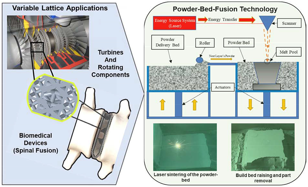
Additively-manufactured concepts (rotating machinery and spinal implant) with variable cell designs to tailor mechanical properties and density in specific locations, as well as powder-bed-fusion additive manufacturing schematic.
Figure 2:
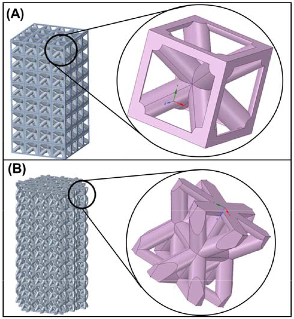
Base unit cell structures utilized in the hybrid structure development as seen via CAD-model.
By leveraging a customized lattice creation approach within CAD software PTC Creo®, along with metal additive manufacturing via powder-bed-fusion, Ti6Al4V structures with different lattice configurations were manufactured. This work’s primary objective is to analyze how customized macro lattices based on HCP and BCC crystal structures affect the overall mechanical properties such as strength and stiffness and how those properties compare to the base material and the base BCC and HCP designs. Five separate “macro-lattice” designs were created via customized assembly techniques in PTC Creo®, resulting in seven total structures to be tested, including the HCP and the BCC base designs, serving as experimental controls (see Table 1). Each macro-lattice design, as shown in Fig. 3, was customized to provide different crystal structures in different areas, such as outside or inside, configured in columns or rows, or even configured in a checkered/alternating arrangement. After designing each structure and producing via PBF, samples were tested under uniaxial compression loading, and failed samples were analyzed via optical and scanning electron microscopy (SEM) to understand the damage mechanisms and effects of configuration on overall structural performance. This work demonstrates lattices’ customizability concerning spatial compressive performance and properties and can be applied to structural light-weighting across many industries and applications.
Table 1:
Comparison of CAD and experimental lattice volumes for each of the specimens. Note that an expansion value has been accounted for concerning our system’s slicing software’s tendency to over-build attices on the 200-300μm length scale.
| Specimen | CAD Lattice Volume (mm3) | Experimental Lattice Volume (mm3) | Percent Difference from CAD Model (%) |
|---|---|---|---|
| HCP | 752 | 824 | 8.70% |
| BCC | 477 | 479 | 0.38% |
| Checkered | 579 | 619 | 6.43% |
| Row-Layered | 648 | 648 | −0.03% |
| Column Layered | 605 | 605 | 0.07% |
| HCP Outer BCC Inner | 512 | 497 | −3.12% |
| HCP Inner BCC Outer | 507 | 533 | 4.81% |
Figure 3:
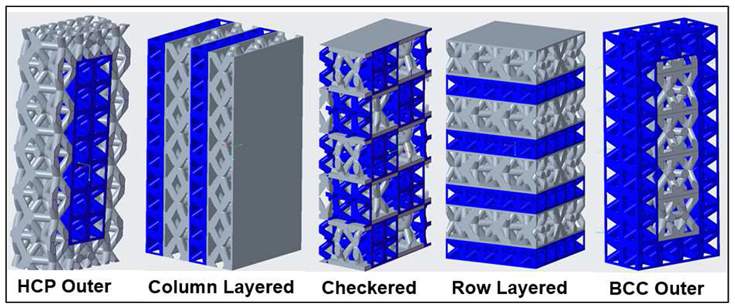
Computer-Aided Design (CAD) representations showing the five designs used in this study. BCC unit cells are pictured in blue, whereas HCP unit cells are pictured in gray. Joining sections are outlined in gray.
2.0. Materials and methods
2.1. Macro-lattice CAD-design:
Macro-lattice designs were created using the CAD software PTC Creo® (Boston, MA, USA). Creo®’s lattice tool was used to create the different unit cells in part files, and then cell arrangements were created from the part files and combined into assembly files to create the overall designed structures. Each printed structure (besides the HCP structure) maintained a 7.5mm square cross-section and 15mm height, while the HCP structure maintained a 10mm cross-section with 5mm hexagonal side lengths.
Depending on the configuration and designs, 3 to 4 unit cells span the cross-section while 6 to 10 span the height. The HCP unit cell’s size was slightly larger in height ~3mm than the BCC (1.76mm) due to the added struts. The BCC strut sizes were 0.7mm (diameter) for the diagonal struts and 0.5mm for the outside struts. For the HCP model, all struts were 0.4mm. Moving from left to right in Fig. 3, the HCP-Outer model’s innermost unit cells were stripped and replaced with BCC unit cells, which was also the case (but reversed) for the BCC-Outer design. For the column-layered design, separate vertical columns of different HCP and BCC unit cells are arranged with matching heights. Note that symmetric thin walls (thickness of 0.125mm-0.25mm) were included on separate sides of each combinatorial structure (shown as gray slabs) to account for the mismatch in the HCP contact area and BCC unit cells, enabling the sound connection between the lattices. The Row-Layered structure was given similar characteristics to the Column-Layered except that the rows have been alternated and horizontal regions of thin solid material placed between adjacent HCP and BCC rows. The checkered structure involves alternating rows of distinct HCP/BCC arrangements within each row resulting in a checkerboard configuration when viewed from the specimen’s top. This pattern proceeds upward until the structure consists of a 2 to 1 height ratio consistent with ASTM compression test standards [12].
2.2. Processing via powder-bed-fusion technology:
Samples were manufactured via powder-bed-fusion technology in a 3D Systems Pro200 system (see Fig. 1), a 3D-Printing method utilizing two main 140mmx140mm reservoirs (one for extra powder and one for printing or the “build-side”), and enclosed in a controlled argon environment <500ppm O2 content at 30°C to limit moisture content. On each layer, a roller is used to transport a thin layer of powder across the top surface from the compacted powder reservoir onto the build surface, as shown schematically in Fig. 1. The powder used in this study was virgin Titanium Grade 23 (LaserForm® Ti6Al4V ELI, Gr. 23) in the particle size range of 5-25μm (evaluated via SEM), and the parts were built upon a Titanium Grade 2 (commercially pure) plate of ~12mm thickness. On each layer, the build side drops 45μm, and 65μm powder is scraped onto the surface, where the carbide-coated roller subsequently compacts the powder down onto the substrate by rolling back over to the build side, resulting in a compacted layer of powder at the desired layer thickness. At this point, a concentrated high-power laser with a focal point at the build surface (~60μm beam diameter) rasters along the surface, outlining the cross-section shape at the given layer (as shown in Fig. 1). All samples were printed on the plate in the opposite direction of argon flow to limit spatter accumulation on the printed components, which increased the overall build quality. This rapid prototyping technique is best known for its ability to 3D print metals, its high dimensional accuracy, and a better surface finish than other metal-based additive manufacturing methods. Recommended Ti6Al4V processing parameters achieving >99.5% relative density for solid bulk specimens were used (30μm layer thickness, 167W laser power, 2400mm/s scanning speed, 70μm hatch spacing). Seven specimens for each configuration were produced on the same build plate, with four specimens of each set used for compression testing. It is important to note that an expansion has been accounted for regarding our system’s slicing software’s tendency to over-build lattices on the 100 to 300μm length scale. More specifically, the printer’s resolution results in overbuilding to the strut’s horizontal (X/Y) dimensions, which is accounted for volumetrically in the designed volumes.
2.3. Metallography, testing, and damage-surface imaging:
After processing, samples were raised from the powder bed build side (shown in Fig. 1) and removed from the build-plate via a band saw cutter. Each sample was ground down to remove the support structures in preparation for compression testing. Each sample’s experimental volumes were also measured by weighing them and assuming a density of 4.42g/cm3 for Ti6Al4V. Each configuration was tested in an Instron compression testing setup, using a constant crosshead displacement rate of 1.3mm/sec. For stress calculation, the effective solid cross-section was utilized as the cross-sectional area. Failed samples were mounted on a conductive peg for optical and Field-Emission “FESEM” electron imaging. For high magnification microstructural imaging, a single BCC sample was mounted in a phenolic resin, ground using SiC paper from 60-2000 grit to reveal the inner portion of a strut, polished via aluminum suspension from 1μm to 0.05μm, and etched via Kroll’s reagent (46mL DI water, 3mL nitric acid, 1mL hydrofluoric acid).
3.0. Results and discussion
Customized lattice structures with variable unit cell geometries were designed via CAD and manufactured using powder-bed-fusion technology. Five separate configurations and two control specimens, BCC and HCP, were tested under compression to understand the resulting properties in comparison to both the unit cell architecture and the base control model. Failure analysis was performed using optical and SEM imaging to help substantiate the compression results.
3.1. Lattice structure and performance under compressive loading:
Lattice design and configuration had a remarkable effect on the structures’ mechanical response under compressive loading. Table 2 shows the elastic modulus, 0.2% offset yield strength, and ultimate compressive strength for each of the samples. The yield strength is calculated from the original elastic region and doesn’t consider any subsequent hardening of the structures at higher strain values. Figs. 4 and 5 show the stress-strain plots as well as the overall strengths and moduli. It is important to note that the stress values are concerning a fully dense specimen occupying the same specimen volume along the cross-section. Also, the compression test was stopped when a specimen exhibited a noticeable and sudden drop in stress. All lattices exhibited plastic deformation as indicated from the stress-strain plots with ultimate compressive strengths higher than the yield. Additionally, all samples maintained regions of multiple failures as indicated by slight troughs in specific regions of the graph, except for the pure HCP model, which deformed in a more monolithic manner without additional displacement after initial failure (a single continuous stress-strain plot). The base HCP model maintained a higher modulus and compressive yield strength in comparison to the BCC model - 59.2 ± 6.4GPa and 42.0 ± 15.6MPa, 15.1 ± 3.8GPa and 229.7 ± 16.8MPa, respectively.
Table 2:
Tabulated values for the moduli and strengths of the seven different lattice structure designs.
| Configuration | Modulus (GPa) | Compressive Yield Strength (MPa) | Compressive Ultimate Strength (MPa) | Theoretical Porosity from CAD (%) |
|---|---|---|---|---|
| BCC | 15.1 ± 3.8 | 229.7 ± 16.8 | 325.5 ± 7.9 | 62.8 |
| HCP | 59.2 ± 6.4 | 342.0 ± 15.6 | 454.6 ± 42.4 | 64.4 |
| BCC Outer | 13.2 ± 0.5 | 225.0 ± 5.6 | 301.6 ± 7.7 | 63.4 |
| HCP Outer | 15.5 ± 1.3 | 265.5 ± 17.5 | 347.1 ± 5.3 | 65.3 |
| Checkered | 56.0 ± 12.9 | 409.9 ± 76.7 | 556.3 ± 20.0 | 54.9 |
| Column Layer | 76.5 ± 20.5 | 511.1 ± 125.5 | 663.8 ± 8.5 | 52.9 |
| Row Layered | 21.3 ± 0.8 | 416.0 ± 10.8 | 560.7 ± 24.0 | 53.8 |
Figure 4:
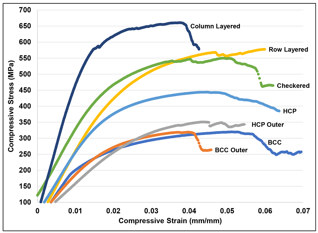
Representative compressive stress-strain plots of each configuration.
Figure 5:
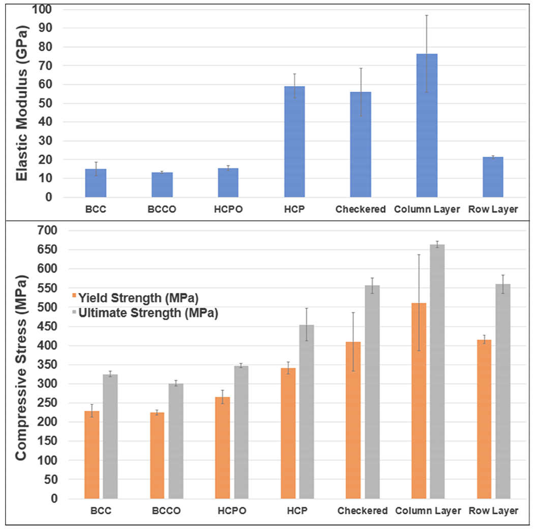
Elastic moduli and compressive strengths of each lattice configuration.
The Column-Layered configuration was stiffest and strongest through both the yield and ultimate strengths - 76.5 ± 20.5GPa, 511.1 ± 125.5MPa, and 663.8 ± 8.5MPa, respectively. This results in as high as 220% increase in yield strength relative to the BCC configuration and a 150% increase relative to the HCP base model. The checkered configuration, as shown in both the plots of Fig. 4 and Fig. 5, maintained a modulus within 6% of the HCP structure, but an increase in the yield and ultimate strengths of 20% and 22%, respectively, indicating similar deformation characteristics with an increase in the overall strength of the structure. The HCP-Outer and BCC-Outer lattice structures were within 3-13% of the base BCC model’s modulus, and the Row-Layered structure was within 40% of the BCC modulus, which is furthered by the stress-strain plot of Fig. 4 that shows the BCC, BCC-Outer, and HCP-Outer plots congregated close to one another with similar deformation characteristics. The BCC-Outer and HCP-Outer models were also within 2-16% of the BCC base structure’s yield strengths and 7% of the ultimate compressive strengths, indicating that these structures align with the base BCC model, with no apparent effect on the mechanical properties. Interestingly, while the Row-Layered configuration was within 40% of the BCC modulus (at 21.3 ± 0.8GPa), its strengths were 22-23% higher than the HCP model at 416.0 ± 10.8MPa and 560.7 ± 24.0MPa, respectively, indicating that the structure deforms similar to the BCC configuration but with significantly higher strength.
3.2. Lattice structure deformation characteristics:
Optical and SEM images help understand the various macro-lattice configurations’ deformation modes. Fig. 6 highlights the microstructures and standard features at high magnification within the structures. As shown in Fig. 6A, a Widmanstatten microstructure typical to AM-produced titanium was observed with highly disordered primary α-laths ranging from 5 to 50μm in length within each of the lattice structures. This α’ martensite microstructure forms due to the rapid cooling from a β-phase field with limited time for the α-laths to grow from within prior β-phase grains, which are typically columnar in nature [13,14]. From Fig. 6B, all samples underwent a mixed failure mode of cleavage and dimple rupture, indicating a combination of brittle and ductile deformation. Additionally, Fig. 6C shows a characteristic failure image of sheared struts near a region of void space, i.e., a joint for the struts, indicating that these regions may serve as stress concentrations within the bulk structures. Since all specimens had experienced very similar micro-scale fractures on the struts, it was determined that microstructure was not a critical factor in how these materials failed, but more due to the lattice structures’ design that contributes to the failure and properties. More specifically, the HCP lattice (Fig. 7) failed along 45° lines near the structure’s base, but the structure was contained without full-scale fracture. These fractures occurred at the peak of the HCP stress-strain curve and resulted in reduced stress and load-carrying capacity over continued strain. The BCC lattice showed similar stress-strain characteristics; however, the BCC arrangement’s bottom row entirely collapsed, resulting in reduced load-carrying capability over increased strain. Fig. 8A shows the complete row fracture common in the Row-Layered structures, leaving nearly a complete section of the structure without an HCP row. However, the Column-Layered structure (Fig. 8B) exhibited a larger-scale crack propagation through both the BCC and HCP regions at 45° relative to the tested direction. It is important to note that the cracks were partially deflected within the BCC column but propagated heavily through the HCP, indicating that there are preferential crack planes within the BCC region and not within the HCP structure. Interestingly, the Checkered structure (Fig. 8C) showed 45° crack formation in the HCP regions that bridged from one to another, without failure in the BCC regions. The HCP-Outer configuration (Fig. 8D) and the BCC-Outer configurations (not shown) showed no surface cracking or fracture, indicating that failure occurred on the inside of the structure.
Figure 6.
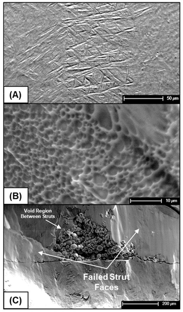
SEM images of the microstructure along with the types of fracture seen. (A) Microstructure of an etched (Kroll’s reagent) strut. (B) Dimple fracture in the Column Layered configuration. (C) Cleavage fracture observed in the Row-Layered configuration.
Figure 7.
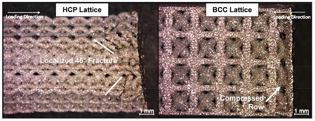
Stereoscope images of the fractured surfaces in the base BCC and HCP structures.
Figure 8:
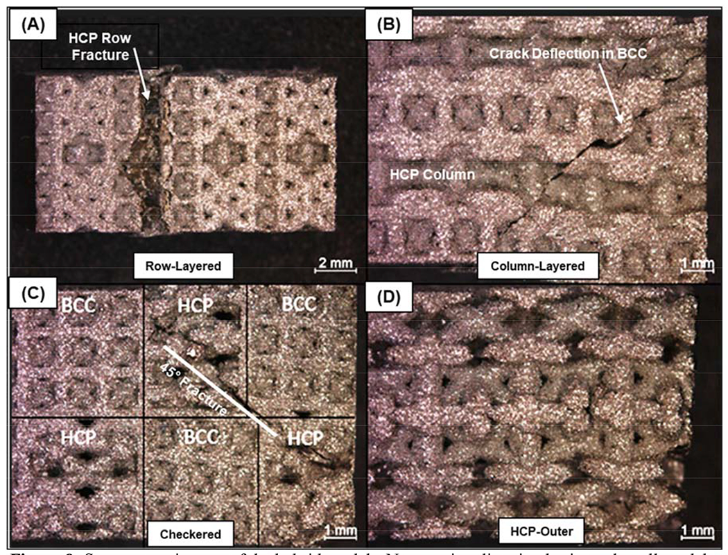
Stereoscope images of the hybrid models. Note testing direction horizontal to all models. (A) Collapse of an HCP layer in the Row-Layered structure. (B) Fracture in the Column-Layered model. (C) Fracture in the Checkered model (the BCC and HCP parts have been labeled for clarity purposes). (D) No external fractures in the HCP-Outer model.
3.3. Relating lattice structure design to compressive performance and deformation:
Finite element analysis (FEA) was performed on single BCC and HCP unit cells to understand how such units absorb energy, generate stress, and fail under compressive loading. Individual CAD files were loaded into ANSYS™ Mechanical and subjected to small vertical displacements of 0.01mm on the top surface elements (applied in the direction into the unit cell), with a single fixed face on the bottom of the unit cell and free lateral movement to simulate a simple compression test. A linear-elastic model was utilized for Ti6Al4V (107 GPa Modulus, 1100 MPa Yield Strength, 0.32 Poisson ratio). Each simulation contained between 20,000 and 25,000 nodes, and mesh refinement studies showed that smaller element size had little to no effect on the resulting stresses. The prescribed displacement generates a reaction force resulting in stresses that are seen in both Fig. 9A and 9B for the BCC and HCP inspired unit cells, respectively. While the actual stress values are less important than the stress concentrations for this study’s purpose, the BCC model shows the vertical outer struts absorbing most of the stress under loading (orange color indicative of higher stress). It is important to note that the vertical strut in this simulation is exerting approximately four times the actual load due to the model only accounting for ¼ of the actual size compared to the actual BCC structure, which has connected edges in the as-printed structures. The concentration of stress along the outer struts substantiates the BCC control composition’s tendency to compact before internal failure along one of the 45° planes shown in the HCP model. This affected the Column-Layered configuration’s deformation behavior (Fig. 8B) as there was a tendency for a preferential deformation path around the outer edges of the BCC regions, leading to the deflection of the overall crack. Because of the crack deflection, there was likely an increased amount of energy required to fracture the column layered sample, contributing to the overall higher stiffness and strength values compared to the other main lattice designs.
Figure 9:
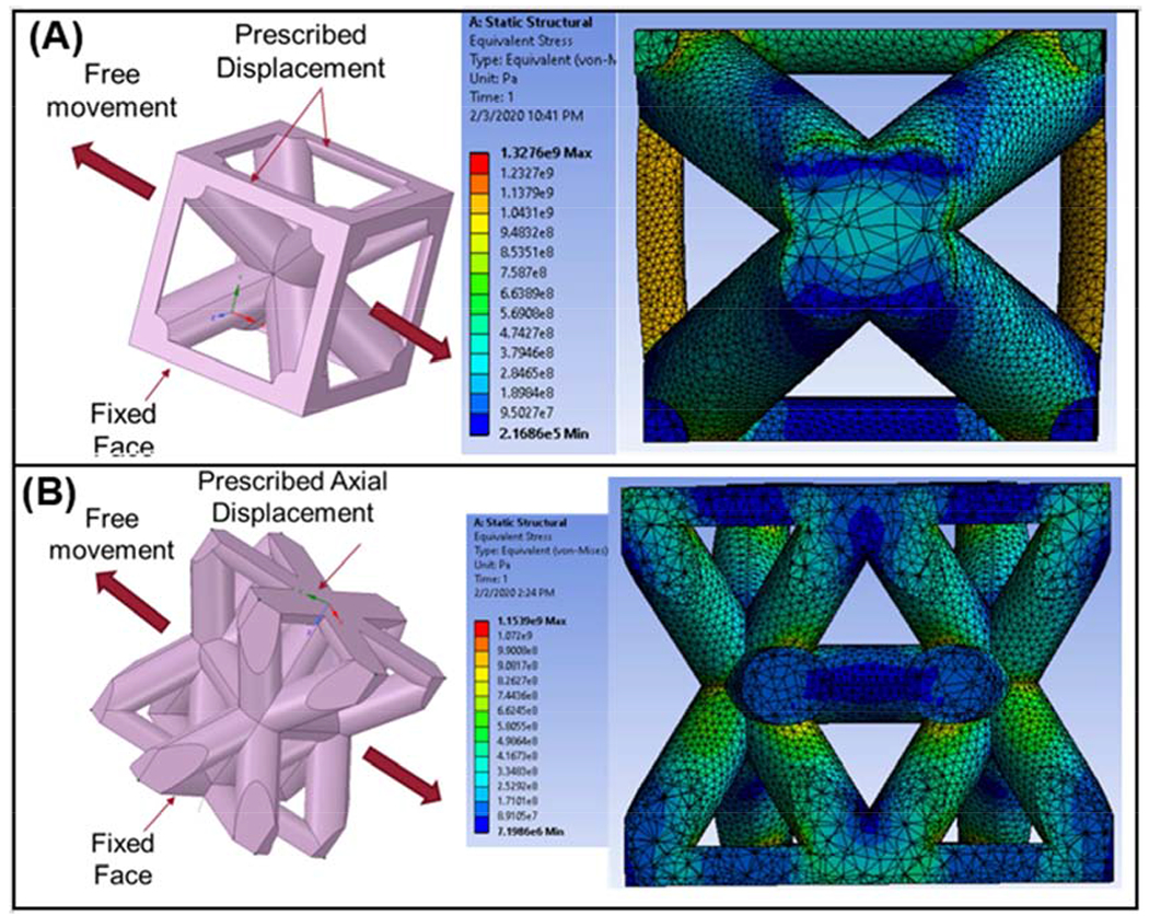
Finite element analysis of single unit cells for BCC (top) and HCP (bottom). Note that deformations are exaggerated on the cross-section cutaway views.
In contrast to the BCC control configuration, the HCP (Fig. 9B) unit cell exhibited high stress on the angled struts, along with low-stress concentration on the horizontal members between the angled struts. Since the horizontal connector struts don’t absorb much energy, this may limit the angled struts’ ability to deflect, contributing to the 45° failure mechanisms observed in most of the macro-lattices shown in Fig. 8. More specifically, the HCP unit cells have many different planes. Any of the absorbing energy struts can fracture, causing a single unit cell to fail and generate higher stresses in the surrounding cells and initiate similar failure and fracture propagation. This was evident within the Row-Layered, Column-Layered, and Checkered configurations and is also substantiated by the strengths and stiffness values close to the HCP, with varying degrees of improvement to the BCC shouldering some of the overall load and prohibiting large scale crack propagation throughout the structures. The BCC-Outer and HCP-Outer configurations were more challenging to analyze as the failures were internal to the structure itself. However, in both cases, deformation was akin to the BCC configuration owing to the strength and stiffness values achieved. Additionally, the solid slab joining the two cell types had a minimal effect on the properties, as the deformation characteristics are clearly described by the base unit cells’ overall failure mechanisms. Further, because the porosities were within ~10% of one another, it is assumed that the deformation mechanisms are due more to lattice design than the different porosity values of the structures themselves. Most importantly, however, this analysis shows that the base unit cell constituents’ failure characteristics can provide insights into the larger structures that have been designed with multiple different cell configurations. Because each of these structures had slightly different properties due to the design characteristics and failure mechanisms, it is clear that base constituents can be used to perform first-generation analysis before even printing test samples, saving significant amounts of time and energy in the experimentation process.
Other works utilizing Ti6Al4V have shown variable properties and performance in comparison to those in the current work. Zadpoor et al. investigated the relationship between experimental, analytical, and computationally predicted properties in cellular “non-auxetic” Ti6Al4V structures comprised of relative densities as high as 50% [7]. In comparison to the current study, yields strengths were reported in the range of 150-300Mpa, and moduli in the range of 10-30GPa, indicating that the structures in the present study (see Fig. 5) fall along with the upper range in comparison to macro-lattices of the diamond, cube, or rhombic dodecahedron type (especially the column-layered configuration). Despite having lower densities than the reported results, the present work utilized solid walls that likely contributed to higher strengths even with comparable overall porosities. Additionally, the strut quality and fracture surfaces were comparable to the work of Zhao et al., who investigated commercially pure titanium lattices processed via powder bed fusion [15]. The tetrahedron and octahedron lattices in that study exhibited unmelted particles along the various struts and flat fracture surfaces like that shown in Fig. 6C. While this study looked primarily at fatigue failure, the static properties were similar to those shown in the present study. In comparison to the analogy of crystal structures to macro-lattice designs, as was done in the work of Pham et al. [9], most configurations in the present study show lack of resistance to crack propagation after the first large-scale cracks begin forming [9]. Theoretically, as actual crystal microstructures start to deform from a compressive load plastically, the atoms will start blocking the motion due to intramolecular forces. While the analogous crack-deflection/turning occurs to a certain extent in the Row-Layered and the BCC/HCP outer configurations, causing toughening behavior, the other lattice designs suffered large-scale crack propagation. The previous work from Pham et al. [9] utilized lattices with high energy absorption that were created using combinations of FCC and BCC unit cells, unlike this experiment with BCC and HCP, indicating that there may be additional complications arising from the mismatch in unit cell lattices and connection points [9]. Additionally, Pham et al. reported 316L stainless lattices containing roughly 8 “meta grains” separated by high angle grain boundaries and achieving yield stress of about 50 MPa, with significant toughening behavior (rising stress-strain curve) under compaction. The present work utilized Ti6Al4V that exhibited continued fracture after the initial failure, a brittle overall characteristic previously reported as common to the material in the as-processed condition via PBF [13]. In the present work, the highest yield stress achieved is 497 MPa, with comparable overall porosity to that in the work of Pham et al. [9]. Concerning the theoretical compressive strength, this gives the 316L sample a yield efficiency of 30% (Structure yield strength/theoretical * 100) and the Ti64 structure a yield efficiency of 51%, assuming that the stress was found by assuming a 100% dense cross-section, indicating that the overall yield efficiency of the present structures is higher, likely at the expense of toughness as has been expanded upon in ref. 16 [16]. These aspects point out that the present study’s macro-lattices exhibit high efficiency and can be configured to work in situations with varying performance requirements.
4.0. Conclusions
Novel Ti6Al4V macro-lattices based on BCC and HCP metallic crystal structures were designed, fabricated via selective laser melting, and tested under compression to understand cell configurations’ effects on compressive deformation. Custom CAD-assembly techniques were utilized to design the structures with five different lattice configurations with an overall porosity of 53 to 65%. The configurations exhibited 0.2% offset compressive strengths as high as 220% greater than the control BCC model (229.7 ± 16.8MPa) and varying degrees larger than the HCP control model (342.0 ± 15.6MPa). Elastic moduli ranged from 13 to 77 GPa in all configurations. Between the designed configurations, as high as 74% difference was observed in compressive strength and 71% variation in elastic modulus, indicating the effects of unit cell placement and design on compressive properties alone. Supplemental finite-element-analysis and optical microscopy aids in understanding the properties and interesting failure mechanisms of each configuration, namely, that the BCC structure maintained regions of higher stress concentration around the periphery of the unit cell, causing crack path change within most of the configurations. The Column-Layered arrangement of BCC and HCP lattices resulted in the highest stiffness and yield strength compared to all other lattice designs (76.5 ± 20.5GPa, 511.1 ± 125.5MPa, respectively), owing to high crack deflection and toughening of the structure under compressive loading. Our work demonstrates the ability to leverage advanced manufacturing methods to tailor the structural performance of multifunctional metallic components via controlled unit cell characteristics and location within the bulk structure.
Supplementary Material
Highlights.
Designing and printing of variable macro-lattice structures of Ti6Al4V using SLM-based AM.
Measure the compressive deformation behavior of macro-lattice structures.
Both strength and failure mode can be influenced by varying macro-lattice designs.
Finite element analysis helped us understand the deformation behaviors in macro-lattice structures.
5.0. Acknowledgments
The authors would like to acknowledge financial support from the National Science Foundation under the grant number NSF-CMMI 1934230 (PI - Bandyopadhyay) and the National Institute of Arthritis and Musculoskeletal and Skin Diseases of the National Institutes of Health under Award Number R01 AR067306-01 (PI - Bandyopadhyay). The content is solely the authors’ responsibility and does not necessarily represent the official views of the National Institutes of Health.
Footnotes
Publisher's Disclaimer: This is a PDF file of an unedited manuscript that has been accepted for publication. As a service to our customers we are providing this early version of the manuscript. The manuscript will undergo copyediting, typesetting, and review of the resulting proof before it is published in its final form. Please note that during the production process errors may be discovered which could affect the content, and all legal disclaimers that apply to the journal pertain.
Declaration of Interest
None.
Data availability statement
All raw data for this study has been presented in this manuscript.
Declaration of interests
The authors declare that they have no known competing financial interests or personal relationships that could have appeared to influence the work reported in this paper.
8.0 References
- [1].Bourell D, Kruth JP, Leu M, Levy G, Rosen D, Beese AM, Clare A, Materials for additive manufacturing, CIRP Ann. - Manuf. Technol 66 (2017) 659–681. doi: 10.1016/j.cirp.2017.05.009. [DOI] [Google Scholar]
- [2].Bandyopadhyay A, Traxel KD, Invited review article: Metal-additive manufacturing—Modeling strategies for application-optimized designs, Addit. Manuf 22 (2018) 758–774. doi: 10.1016/j.addma.2018.06.024. [DOI] [PMC free article] [PubMed] [Google Scholar]
- [3].Gibson I, Rosen D, Stucker B, Additive Manufacturing Technologies, 2015. doi: 10.1007/978-1-4939-2113-3. [DOI] [Google Scholar]
- [4].Bose S, Ke D, Sahasrabudhe H, Bandyopadhyay A, Additive manufacturing of biomaterials, Prog. Mater. Sci 93 (2018) 45–111. doi: 10.1016/j.pmatsci.2017.08.003. [DOI] [PMC free article] [PubMed] [Google Scholar]
- [5].Uriondo A, Esperon-Miguez M, Perinpanayagam S, The present and future of additive manufacturing in the aerospace sector: A review of important aspects, Proc. Inst. Mech. Eng. Part G J. Aerosp. Eng 229 (2015) 2132–2147. doi: 10.1177/0954410014568797. [DOI] [Google Scholar]
- [6].Wegst UGK, Bai H, Saiz E, Tomsia AP, Ritchie RO, Bioinspired structural materials, Nat. Mater (2015). doi: 10.1038/nmat4089. [DOI] [PubMed] [Google Scholar]
- [7].de Jonge C, Kolken H, Zadpoor A, Non-Auxetic Mechanical Metamaterials, Materials (Basel). 12 (2019) 635. doi: 10.3390/ma12040635. [DOI] [PMC free article] [PubMed] [Google Scholar]
- [8].Kolken HMA, Zadpoor AA, Auxetic mechanical metamaterials, RSC Adv. (2017). doi : 10.1039/c6ra27333e. [DOI] [PMC free article] [PubMed] [Google Scholar]
- [9].Pham M-S, Liu C, Todd I, Lertthanasarn J, Damage-tolerant architected materials inspired by crystal microstructure, Nature. 565 (2019) 305–311. doi: 10.1038/s41586-018-0850-3. [DOI] [PubMed] [Google Scholar]
- [10].Schaedler TA, Jacobsen AJ, Torrents A, Sorensen AE, Lian J, Greer JR, Valdevit L, and Carter WB. “Ultralight Metallic Microlattices.” Science, New Series, 334, no. 6058 (2011): 962–65. Accessed January 29, 2021. http://www.jstor.org/stable/41351742. [DOI] [PubMed] [Google Scholar]
- [11].Maskery I, Aboulkhair NT, Aremu AO, Tuck CJ, Ashcroft IA, Wildman RD, Hague RJM, A mechanical property evaluation of graded density Al-Si10-Mg lattice structures manufactured by selective laser melting, Materials Science and Engineering: A, Volume 670, 2016, Pages 264–274, ISSN 0921-5093, 10.1016/j.msea.2016.06.013.(http://www.sciencedirect.com/science/article/pii/S092150931630658X) [DOI] [Google Scholar]
- [12].ASTM Standard E9-09, Standard Test Methods of Compression Testing of Metallic Materials at Room Temperature, Annu. B. ASTM Stand 301 (2012) 92–100. doi: 10.1520/E0009-09.2. [DOI] [Google Scholar]
- [13].Liu S, Shin YC, Additive manufacturing of Ti6Al4V alloy: A review, Mater. Des 164 (2019) 107552. doi: 10.1016/j.matdes.2018.107552. [DOI] [Google Scholar]
- [14].Rafi HK, Karthik NV, Gong H, Starr TL, Stucker BE, Microstructures and Mechanical Properties of Ti6Al4V Parts Fabricated by Selective Laser Melting and Electron Beam Melting, J. Mater. Eng. Perform 22 (2013) 3872–3883. doi: 10.1007/s11665-013-0658-0. [DOI] [Google Scholar]
- [15].Zhao D, Huang Y, Ao Y, Han C, Wang Q, Li Y, Liu J, Wei Q, Zhang Z, Effect of pore geometry on the fatigue properties and cell affinity of porous titanium scaffolds fabricated by selective laser melting, J. Mech. Behav. Biomed. Mater 88 (2018) 478–487. doi: 10.1016/j.jmbbm.2018.08.048. [DOI] [PubMed] [Google Scholar]
- [16].Ritchie RO, The conflicts between strength and toughness, Nat. Mater (2011). doi : 10.1038/nmat3115. [DOI] [PubMed] [Google Scholar]
Associated Data
This section collects any data citations, data availability statements, or supplementary materials included in this article.


