Abstract
BACKGROUND AND PURPOSE:
Flow-diverting devices are increasingly being considered for large or giant aneurysms with wide necks, which are difficult to treat with coils or clips. These devices are often oversized to achieve good positioning against the artery wall. The objective of this study was to analyze the effect of oversized flow-diverting devices in altering aneurysmal flows and creating hemodynamic environments favorable for thrombosis and aneurysm occlusion.
MATERIALS AND METHODS:
Patient-specific computational fluid dynamics models of 3 cerebral aneurysms were constructed from 3D angiography images. Numeric simulations of the hemodynamics after implanting stents of increasing diameters were performed. The corresponding modifications of hemodynamic variables such as aneurysm inflow rate, average velocity, shear rate, and wall shear stress were calculated and compared.
RESULTS:
The results indicate that because the devices are oversized, the stent cells stretch in the direction of the vessel axis, change cell angles, and result in larger cells. This change in the cell geometry causes a diminution of the hemodynamic performance of the stent. Quantitatively, stent oversizing results in larger values of aneurysm inflow rates, average velocity, shear rate, and wall shear stress compared with nonoversizing cases.
CONCLUSIONS:
The efficacy of flow-diverting devices in modifying intra-aneurysmal flow can be substantially reduced by oversizing the devices. As the level of device oversize increases, aneurysmal hemodynamic variables are significantly less affected.
Endovascular coiling has become the treatment of choice for most intracranial aneurysms. However, it has significant limitations in achieving durable occlusion of large and giant aneurysms because of their propensity for recanalization. Furthermore, many wide-neck aneurysms are difficult or impossible to treat with coils alone or by surgical clipping. These have been the main motivations for the development of FD devices for intracranial aneurysms.1–3 These devices work by promoting thrombosis of the aneurysm, by redirecting the blood flow away from the aneurysm, and by providing a structure to support endothelialization and reconstruction of the parent artery. Initial trials by using FD stents have shown promising results,4,5 but the detailed relationship between the hemodynamic alteration produced by different devices and the outcome of the procedures is not fully understood. Presumably, the intrasaccular thrombosis that takes place after implantation of these devices is caused by the creation of sluggish flows within the aneurysm, characterized by slow and stagnant velocity patterns and low wall shear stress.6 Thus, FD devices are designed as a metallic mesh to be implanted in the parent artery with the main goal of blocking, as much as possible, the flow entering the aneurysm while maintaining adequate flow inside arterial branches. These devices are frequently oversized to achieve adequate appositioning against the parent artery wall—that is, the diameter of the device is selected to exceed the parent artery diameter by at least 0.5 mm or more. Releasing an FD stent in an artery of smaller caliber causes the stent to stretch along the vessel axes and to change the geometry of the stent cells from the reference un-deformed configuration. The objective of this study was to analyze the effect of oversized FD devices on their efficacy to alter aneurysmal flows and create hemodynamic environments favorable for thrombosis and aneurysm occlusion.
Materials and Methods
Vascular Models
Three cerebral aneurysms with wide necks representative of aneurysms that may be considered for treatment with FD devices were selected from our data base for study. Corresponding patient-specific computational models were created from 3D rotational angiography images. These images were acquired during 10-second contrast injections and 180° rotations at 15 frames per second on an Allura flat panel system (Philips Healthcare, Best, the Netherlands). The projection images were reconstructed on a dedicated workstation (XtraVision, Phillips) into 3D datasets of 2563 isotropic voxels. Vascular models of each aneurysm and the connected arteries were constructed by using a seeded region-growing segmentation followed by an isosurface deformable model.7 The geometric models were smoothed and truncated perpendicular to the vessel axes and then were used to generate unstructured grids, filling the vascular volume with tetrahedral elements of approximately 0.2 mm.
Device Models
Braided stent designs were virtually deployed within the vascular models.8,9 The virtual deployment methodology starts by computing the centerline of the parent artery. A discrete cylinder of uniform radius made of triangular elements is generated along this centerline. The initial radius is chosen so that the cylinder is fully contained within the artery. This cylinder is then released under the influence of radial outward forces, smoothing internal forces, and wall contact forces until it is in full contact with the vessel wall. This is achieved by interactively integrating the Newton equations of motion by using the Newmark method.10 The output of this step is the so-called deployed cylinder, which acts as the host surface for different stent designs. A given stent design is represented as a collection of interconnected points in a 2D space (plane). These points are mapped into the deployed cylinder to obtain the final deployed stent.
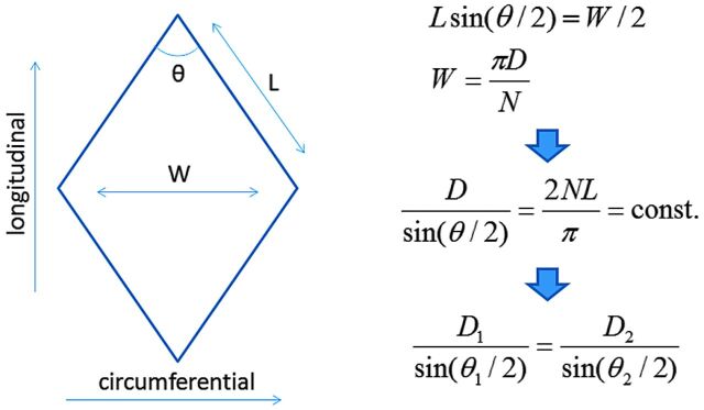
Foreshortening corrections were applied to the stent designs before they were mapped onto the deployed cylinders. For this, the mean deployed cylinder diameter at the aneurysm neck region is first measured. A correction to the stent reference cell angle is computed, using the deployed cylinder diameter and the reference stent diameter. This correction is based on the assumption that the stent wires are inextensible. Therefore, in a single stent cell (Fig 1), a change in the circumferential direction (cell width) due to a change in the diameter of the stent produces a corresponding change in the longitudinal direction (cell height) to keep the wire length constant. This produces a change in the cell angle. The modified angle is computed, and a corrected stent design is generated. This stent design is finally mapped onto the deployed cylinder.
Fig 1.
Calculation of stent cell deformation due to device oversizing. D indicates stent diameter; n, number of cells in the circumferential direction; L, cell wire length; W, cell width; θ, braid cell angle.
For each of the aneurysm models, a single braided stent design with 3 different reference diameters was deployed. The reference diameters were chosen to be +0.0 mm, +0.5 mm, and +1.0 mm based on the deployed cylinder diameter. The stent design consisted of 48 wires braided at 150°(reference angle) and a wire thickness of 48 μm. Once the stents were deployed within the vascular models, the corresponding grids were adaptively refined 4 times to properly resolve the stent wires. The final grids contained between 34 and 68 million elements.
Hemodynamics Models
Blood flow was mathematically modeled with the unsteady Navier-Stokes equations for an incompressible Newtonian fluid with an attenuation of ρ = 1.0 g/cm3 and viscosity μ = 0.04 poise. These equations were numerically solved by using an implicit finite-element formulation and a deflated conjugate-gradients algorithm to accelerate the convergence.11 The stent wires were treated with an immersed boundary approach on the refined unstructured grids.12 Because patient-specific flow conditions were not available, typical flow waveforms measured in healthy subjects were used to specify the inflow boundary conditions.13 Two sets of flow conditions were used for each model. The first (denoted flow 1) corresponds to a mean flow of 3 mL/s and a peak flow of 5 mL/s. The second condition used (denoted flow 2) was obtained by scaling the flow waveform to achieve a similar mean wall shear stress at the inlet of each model of 15 dyne/cm2, as expected from the principle of minimum work.14 Pulsatile CFD simulations were performed for 2 cardiac cycles, and the results are presented for the second cycle. The results of these CFD computations were postprocessed to calculate the following aneurysmal hemodynamic quantities:15 1) inflow rate into the aneurysm, 2) flow velocity averaged over the aneurysm volume, 3) shear rate averaged over the aneurysm volume, and 4) wall shear stress averaged over the aneurysm surface. Subsequently, the reduction of these quantities from the prestenting configuration to each of the stented models was calculated, and the minimum, maximum, and mean of these changes over the cardiac cycle were computed and compared.
Results
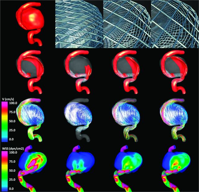
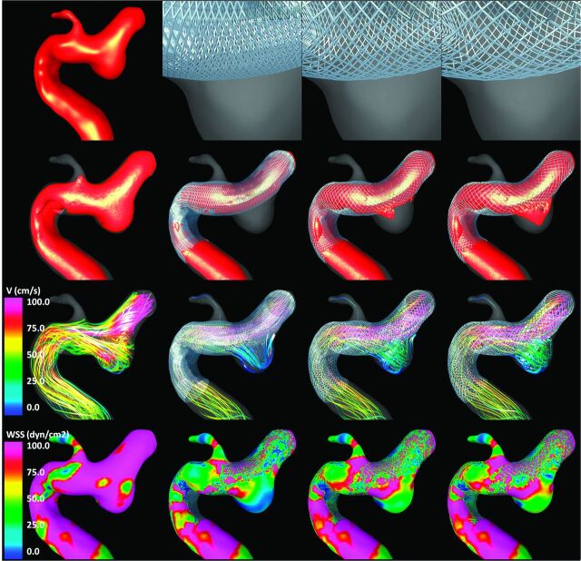
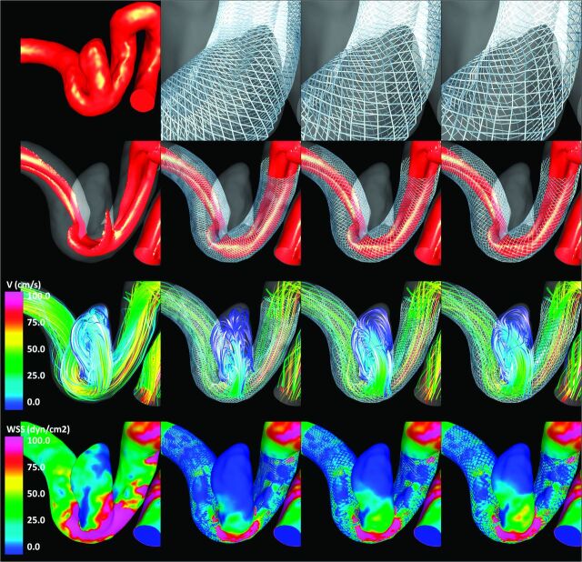
Visualizations of the results obtained for each of the 3 aneurysms are presented in Figs 2–4 , respectively. All visualizations correspond to peak systole of flow condition 1. The top row of each of these figures shows the vascular model of each aneurysm (leftmost panel) and the geometry of the stent cells at the aneurysm neck for each of the 3 stents considered. Because the devices are oversized (left-to-right panels in the figures), the stent cells stretch in the direction of the vessel axis, changing the internal cell angles and resulting in effectively larger cells areas.
Fig 2.
Aneurysm case 1. Columns left to right: prestent, no oversize, 0.5-mm oversize, and 1.0-mm oversize. Rows top to bottom: vascular model and details of stent cells at the aneurysm neck, isovelocity surfaces, velocity-colored flow streamlines, and wall shear stress distribution (all at peak systole).
Fig 4.
Aneurysm case 3. Columns left to right: prestent, no oversize, 0.5-mm oversize, and 1.0-mm oversize. Rows top to bottom: vascular model and details of stent cells at the aneurysm neck, isovelocity surfaces, velocity-colored flow streamlines, and wall shear stress distribution (all at peak systole).
The second row of Figs 2–4 shows isovelocity surfaces depicting the blood streams flowing into the aneurysms before and after stent placement with each of the devices considered. The third row shows the corresponding intra-aneurysmal flow patterns by using streamlines color-coded with the velocity magnitude; the fourth (bottom) row shows the corresponding wall shear stress distributions. These visualizations illustrate the hemodynamic alterations produced by implantation of FD devices of varying diameters. Specifically, the stents block and disrupt the inflow jets, resulting in reduced aneurysmal inflow. In addition, the flow velocity inside the aneurysm sac is substantially reduced after implanting the devices, and the flow structures become simpler and smoother (ie, fewer vortex structures, more parallel streamlines, and less swirling). Finally, the stents also reduce the wall shear stress on the aneurysm sac. All these alterations tend to create a hemodynamic environment that is more favorable for thrombosis and aneurysm occlusion. However, these effects are less pronounced because the FD devices are oversized. In other words, as the diameter of the implanted devices increases, the aneurysm hemodynamics are less affected or modified.
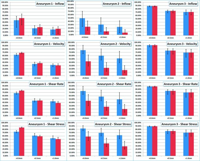
Quantitative results are presented in Fig 5. This figure shows the reduction of aneurysm inflow (row 1), average aneurysm velocity (row 2), average aneurysm shear rate (row 3), and average wall shear stress (row 4). Columns 1–3 show results for aneurysms 1–3, respectively. Each panel shows the reduction of the hemodynamic variables from the pretreatment configuration for both flow conditions considered (blue bars indicate flow 1, and red bars, flow 2). The solid bars show the reduction in the time-average values of the hemodynamic variables, while the error bars indicate the minimum and maximum reductions obtained during the cardiac cycle. The labels “+0.0 mm”, “+0.5 mm,” and “+1.0 mm” indicate the level of oversizing used in each of the poststenting models (0.0 being no oversizing—ie, the stent diameter is equal to the parent artery diameter). These results indicate that choosing devices with diameters similar to those of the parent arteries (ie, no oversizing) produces the largest reductions in all the hemodynamic variables considered in all aneurysms. When devices of diameters 0.5 and 1.0 mm larger than the parent artery diameter are used, the flow variables are substantially increased with respect to the case with no oversizing. This shows that the hemodynamic performance of the devices or their flow-diversion effect decreases significantly as the level of device oversizing increases. The results also show that the degree of flow alteration depends on the parent artery flow rate and the instant of time during the cardiac cycle. In particular, reductions in flow variables are larger for lower flow rates (eg, during diastole) and smaller for larger flow rates (eg, during systole). However, the effect of device oversizing (relative changes from 0.0 to 0.5 mm and to 1.0 mm oversize) seems to be fairly independent from the flow rates.
Fig 5.
Reduction of hemodynamic measures (inflow rate, mean velocity, mean shear rate, and mean wall shear stress) from the prestenting condition obtained with flow-diverting devices with no oversize (denoted +0.0 mm), 0.5-mm oversize, and 1.0-mm oversize in 3 patient-specific aneurysm geometries (denoted aneurysms 1, 2, and 3). Blue bars correspond to flow condition 1, and red bars, to flow condition 2. Solid bars show reduction in time-averaged quantities, while error bars correspond to maximum and minimum reductions obtained during the cardiac cycle.
Discussion
The treatment of intracranial aneurysms has gone through dramatic changes with the introduction of endovascular techniques. Endosaccular coiling of aneurysms is increasingly being used for the treatment of most aneurysms. However, a large rate of aneurysm recurrence is still observed as a consequence of coil compaction in many large and giant aneurysms that require retreatment. The development of new hemodynamic approaches to the treatment of intracranial aneurysms is a major departure from these traditional therapies. Rather than mechanically excluding the aneurysm sac from the circulation, this approach aims at restoring the normal hemodynamics of the parent artery. Placement of an FD device within the parent artery and across the orifice of the aneurysm creates a redirection of the flow through the parent artery and establishes a low-flow hemodynamic state within the aneurysm, which would favor its thrombosis and ultimate occlusion and remodeling.16 The inherent stability of these endoluminal devices maintains a stable long-term hemodynamic environment that promotes aneurysmal thrombosis and potentially avoids aneurysmal recurrence, making this approach very attractive, especially for large and giant wide-neck aneurysms, which have a significant rate of coil compaction and recanalization.
Because the FD does not mechanically exclude the aneurysm from the flow stream but relies on the hemodynamic environment created to initiate thrombosis and remodeling to ultimately seal the aneurysm, the aneurysm is not immediately eliminated. Until the healing of the aneurysm is completed, the aneurysm wall is subject to the stresses and strains imposed by the pulsatile arterial circulation. Furthermore, the aneurysmal wall is subject to the biologic processes related to the local thrombosis, which may initially be potentially damaging. Thus, it is important to accelerate the thrombosis and occlusion of the aneurysm. Presumably, the speed of aneurysm thrombosis and occlusion after treatment with a FD would depend on the degree of flow stagnation and low wall shear stress created within the aneurysm sac. These posttreatment hemodynamic characteristics, in turn, depend on the design of the FD device and specifically on its porosity and pore size or pore attenuation once released in the parent artery.
When treating intracranial aneurysms with FDs, interventionalists frequently need to choose devices with diameters larger than the parent artery (ie, oversized). Although this is not recommended by manufacturers, oversizing is sometimes needed to achieve a good appositioning against the parent artery wall and avoid device migration. In particular, in arteries with significant tapering, endovascular surgeons usually select devices with diameters larger than the largest diameter of the parent artery (typically the most proximal segment). When an oversized device is released within an artery of smaller caliber, it stretches along the artery axis, changing the local geometry of the cells17 (ie, the device does not recover its reference configuration). These changes in the cell geometry alter the local porosity and pore attenuation of the device in the region of the aneurysm. We have used patient-specific computational fluid dynamics models to analyze the effect of these geometric changes in oversized devices on their hemodynamic performance.
To analyze the hemodynamic performance of devices of different diameters, we studied a number of quantitative metrics: 1) aneurysm inflow rate, 2) average blood velocity within the aneurysm, 3) average shear rate of blood flow within the aneurysm, and 4) average wall shear stress. These metrics are useful to characterize the intra-aneurysmal hemodynamic environment and its relation to the development of an intrasaccular thrombus. Aneurysm inflow rate relates to blood flow speed and the creation of regions of slow flow recirculation and stagnation within the aneurysm sac. Low-flow velocity relates to regions prone to thrombus formation.6 Low shear rate relates to the non-Newtonian behavior of blood, which connects blood viscosity, yield stress, and platelet aggregation.18 Wall shear stress measures the frictional force per unit area of blood flow on the aneurysm wall, which relates to the likelihood of platelet adhesion to the wall and thrombus formation near the wall.19 Our simulations show that all these hemodynamic quantities are reduced when an FD device is deployed in the parent artery and across the aneurysm orifice, thus creating an intra-aneurysmal hemodynamic environment that is more favorable for thrombosis and aneurysm occlusion. However, these reductions are affected by the level of device oversizing. Our simulations suggest that selecting devices exceeding the parent artery diameter by 0.5 or 1.0 mm can significantly increase these hemodynamic quantities compared with the nonoversized case. For instance, the results (Fig 5) show that using devices with diameters equal to those of the parent arteries reduces the aneurysm inflow rate by 65% in aneurysm 1, by 41% in aneurysm 2, and by 90% in aneurysm 3. However, if the device has a diameter 0.5 mm larger than that of the parent artery, the inflow rate reductions are 33%, 22%, and 76% for aneurysms 1, 2 and 3, respectively. Similarly, if the device has a diameter 1.0 mm larger than that of the parent artery, the corresponding reductions are 26%, 15%, and 76%. This finding shows that with oversizing, the hemodynamic variables can be up to 50% larger than those in the nonoversized case. This effect is due to the elongation of the device cells in the axial direction, which results in an effective enlargement of the cell areas. For instance, device cells with wire angles of 150° in the reference configuration can change their angle down to about 90° when released in an artery of smaller luminal size (see top row of Figs 1–3).
Fig 3.
Aneurysm case 2. Columns left to right: prestent, no oversize, 0.5-mm oversize, and 1.0-mm oversize. Rows top to bottom: vascular model and details of stent cells at the aneurysm neck, isovelocity surfaces, velocity-colored flow streamlines, and wall shear stress distribution (all at peak systole).
Elongation (or contraction) of the device cells can also occur due to the curvature of the vessels.17 It has been observed that in the outer region of a curved vessel, the cells elongate whereas in the inner region, the cells contract. This effect, though independent of the device oversizing, also contributes to the final cell shape. If the aneurysm is located in the outer curvature, both effects combine, resulting in more elongated cells, thus decreasing flow diversion. On the other hand, if the aneurysm is located in the inner region, the oversizing effect may be compensated, resulting in a more effective flow modification.
The significant variation in the flow-diverting characteristics of FD devices suggests that more precise knowledge of the connection between the hemodynamic environment created immediately after stent placement and the occlusion rate and ultimate procedure outcome is needed. This would allow design of better devices that would create this target environment and selection of the most appropriate device or combination of devices for a particular aneurysm.
This study focused on braided devices of uniform wire thickness. The design parameters (angles, number of wires, diameters) were selected in accordance with typical values found in commercial devices (such as the Pipeline Embolization Device; Chestnut Medical Technologies, Menlo Park, California or Silk; Balt, Montmorency, France). However, the effects highlighted in this article are largely independent of the stent design details.
This work has several limitations, common to most modeling studies, which need to be considered when analyzing the results, including the following: assumption of rigid walls, Newtonian blood properties, limited mesh and time-step resolution, and physiologically realistic–but not patient-specific flow-boundary conditions. The results of our CFD simulations indicate that the hemodynamic performance of the FD devices depends on the arterial flow rate. In particular, the flow diversion and reduction of hemodynamic quantities are more effective for lower flow rates. This feature also suggests more flow-modification efficacy during the diastolic than the systolic phases of the cardiac cycle. Despite these limitations, with all flow conditions and during all phases of the cardiac cycle, it was observed that the hemodynamic performance of the devices decreased when the devices were oversized. Finally, the exact geometries of the stents after deployment are unknown. These are approximated assuming a smooth and slow release; however, in reality, interventionalists may push on the catheter while deploying the device and modify (compress) the cells in the aneurysm neck region. This mechanism was not considered in the current study.
Conclusions
The hemodynamic efficacy of flow-diverting devices in modifying intra-aneurysmal flows can be substantially reduced by oversizing the devices. As the level of device oversize increases, hemodynamic quantities such as aneurysm inflow rate, flow velocity, shear rate, and wall shear stress are significantly less affected. Thus, the selection of devices with diameters larger than those in the parent artery, typically done to achieve a good appositioning against the artery wall, can significantly affect the ability of these devices to create adequate hemodynamic environments that promote fast aneurysm thrombosis and exclusion from the circulation. These observations may help decide which devices to select for treating a given aneurysm or how many devices to deploy.
ABBREVIATIONS:
- CFD
computational fluid dynamics
- FD
flow diverter
Footnotes
This work was supported by Philips Healthcare and Boston Scientific.
References
- 1.Lylyk P, Ferrario A, Pasbon B, et al. Buenos Aires experience with the Neuroform self-expanding stent for the treatment of intracranial aneurysms. J Neurosurg 2005;102:235–41 [DOI] [PubMed] [Google Scholar]
- 2.Lövbald KO, Yilmaz H, Chouiter A, et al. Intracranial aneurysm stenting: follow-up with MR angiography. J Magn Reson Imaging 2006;24:418–22 [DOI] [PubMed] [Google Scholar]
- 3.Szikora I, Berentei Z, Kulcsar Z, et al. Endovascular treatment of intracranial aneurysms with parent vessel reconstruction using balloon and self expandable stents. Acta Neurochir (Wien) 2006;148:711–23 [DOI] [PubMed] [Google Scholar]
- 4.Lylyk P, Miranda C, Ceratto R, et al. Curative endovascular reconstruction of cerebral aneurysms with the Pipeline embolization device: the Buenos Aires experience. Neurosurgery 2009;64:632–42 [DOI] [PubMed] [Google Scholar]
- 5.Szikora I, Berentei Z, Kulcsar Z, et al. Treatment of intracranial aneurysms by functional reconstruction of the parent artery: the Budapest experience with the Pipeline embolization device. AJNR AJNR Am J Neuroradiol 2010;31:1139–47 [DOI] [PMC free article] [PubMed] [Google Scholar]
- 6.Rayz VL, Boussel L, Lawton MT, et al. Numerical modeling of the flow in intracranial aneurysms: prediction of regions prone to thrombus formation. Ann Biomed Eng 2008;36:1793–804 [DOI] [PMC free article] [PubMed] [Google Scholar]
- 7.Cebral JR, Castro MA, Appanaboyina S, et al. Efficient pipeline for image-based patient-specific analysis of cerebral aneurysm hemodynamics: technique and sensitivity. IEEE Trans Med Imaging 2005;24:457–67 [DOI] [PubMed] [Google Scholar]
- 8.Appanaboyina S, Mut F, Löhner R, et al. Simulation of intracranial aneurysm stenting: techniques and challenges. Comput Methods Appl Mech Eng 2009;198:3567–82 [Google Scholar]
- 9.Mut F, Appanaboyina S, Cebral JR. Simulation of stent deployment in patient-specific cerebral aneurysm models for their hemodynamics analysis. In: Proceedings of the American Society of Mechanical Engineers Summer Bioengineering Conference, Marco Island, Florida. June 25–29, 2008 [Google Scholar]
- 10.Bathe KJ. Finite Element Procedures. Englewood Cliffs, New Jersey: Prentice Hall; 1996 [Google Scholar]
- 11.Mut F, Aubry R, Löhner R, et al. Fast numerical solutions in patient-specific simulations of arterial models. Int J Numer Method Biomed Eng 2010;26:73–85 [DOI] [PMC free article] [PubMed] [Google Scholar]
- 12.Cebral JR, Löhner R. Efficient simulation of blood flow past complex endovascular devices using an adaptive embedding technique. IEEE Trans Med Imaging 2005;24:468–77 [DOI] [PubMed] [Google Scholar]
- 13.Cebral JR, Castro MA, Putman CM, et al. Flow-area relationship in internal carotid and vertebral arteries. Physiol Meas 2008;29:585–94 [DOI] [PMC free article] [PubMed] [Google Scholar]
- 14.Murray CD. The physiological principle of minimum work applied to the angle of branching of arteries. J Gen Physiol 1926;9:835–41 [DOI] [PMC free article] [PubMed] [Google Scholar]
- 15.Mut F, Löhner R, Chien A, et al. Computational hemodynamics framework for the analysis of cerebral aneurysms. Int J Numer Method Biomed Eng 2011;27:822–39 [DOI] [PMC free article] [PubMed] [Google Scholar]
- 16.Lieber BB, Stancampiano AP, Wakhloo AK. Alteration of hemodynamics in aneurysm models by stenting: influence of stent porosity. Ann Biomed Eng 1997;25:460–69 [DOI] [PubMed] [Google Scholar]
- 17.Aurboonyawat T, Blanc R, Schmidt P, et al. An in vitro study of the Silk stent morphology. Neuroradiology 2011;53:659–67 [DOI] [PubMed] [Google Scholar]
- 18.Mazumdar J. Biofluid Mechanics. Singapore: World Scientific; 1992 [Google Scholar]
- 19.Zhan F, Fan Y, Deng X. Swirling flow created in a glass tube suppressed platelet adhesion to the surface of the tube: its implication in the design of small-caliber arterial grafts. Thromb Res 2010;125:413–18 [DOI] [PubMed] [Google Scholar]


