Abstract
In this contribution, the complex behaviour of the Hindmarsh–Rose neuron model under magnetic flow effect (mHR) is investigated in terms of bifurcation diagrams, Lyapunov exponent plots and time series when varying only the electromagnetic induction strength. Some exciting phenomena are found including, for instance, various firings patterns by applying appropriate magnetic strength and Hopf-fold bursting through fast–slow bifurcation. In addition to this, the interesting phenomenon of Hopf bifurcation is examined in the model. Thus, we prove that Hopf bifurcation occurs in this memristor-based HR neuron model when an appropriately chosen magnetic flux varies and reaches its critical value. Furthermore, one of the main results of this work was the optimal control approach to realize the synchronization of two mHR. The main advantage of the proposed optimal master–slave synchronization from a control point of view is that, in the practical application, the electrical activities (quiescent, bursting, spiking, period and chaos states) of a neuron can be regulated by a pacemaker (master) associated with biological neuron (slave) to treat some diseases such as epilepsy. A suitable electronic circuit is designed and used for the investigations. PSpice based simulation results confirm that the electrical activities and synchronization between coupled neurons can be modulated by electromagnetic flux.
Keywords: Bifurcation, Electromagnetic induction, Memristor, Synchronization, Neural circuit
Introduction
In neuroscience, there remain two main problems whose solutions are related and investigated in nonlinear dynamics and chaos. As described by Valera et al. (2001), the first problem is that of the integrated behaviour of the nervous system. Its main goal is to understand the mechanism that enables the units and different parts of the nervous system to work together. Such a phenomenon linked to the synchronization of nonlinear dynamical oscillators. The second problem, named neural coding problem, drew the attention of many researchers such as Sejnowski (1995) and Abeles (2004), consists in understanding how neurons encode and exchange information in the nervous system. Solutions to such problems were analysed through both the knowledge of different types of behaviours available to chaos synchronization and nonlinear dynamical systems (Sejnowski 1995; Fetz 1997). Indeed, dynamic behaviours of neurons are significant to acquaintance with the signal exchange in the brain or even with related diseases; as a result, previous works have been investigated (Hodgkin and Huxley 1952; Fitzhugh 1961; Ermentrout and Terman 2010; Morris and Lecar 1981; Ma et al. 2019; Njitacke et al. 2019a; Chay 1985; Li et al. 2004; Yang and Lu 2007). In other words, in Hodgkin and Huxley (1952), Hodgkin and Huxley use the experimental results obtained for the giant axon of squid to represent the ion fluxes and the permeability changes of an excitable membrane in terms of molecular mechanisms. Similarly, in Morris and Lecar (1981), Morris–Lecar propose a biological neuron model which makes it possible to reproduce the multiple oscillatory behaviors linked to the conductance of Ca++ and K+ ions in the muscle fiber of the giant barnacle. Likewise, in Chay (1985), Chay proposes an electrophysiological model which is used to describe the dynamics of β-cells in the pancreas. Based on this, several others models were established in particular Hindmarsh–Rose neuron model for studying mode selection of neurons (Selverston et al. 2000; Hindmarsh and Rose 1982, 1984; Pinto et al. 2000). Here, we focus on the Hindmarsh–Rose (HR) neuronal oscillator proposed by Hindmarsh and Rose (1984), after the formulation of their two-equation model (Hindmarsh and Rose 1982). Their main goal was to model the synchronization of firing two snail neurons directly, without the use of the Hodgkin–Huxley (HH) equations (Hindmarsh and Rose 1982; Coombes and Bressloff 2005). Hence, to create a neuron model that exhibits triggered firing, some modifications were done on the two-equation model (by adding an adaptation variable, representing the slowly varying current, that changed the applied current to an effective applied one) to obtain the three-equation model (Hindmarsh and Rose 1984; Coombes and Bressloff 2005). This model has been trendy in studying the biological properties of spiking and bursting neurons. A few years later, several works confirm that the fluctuation of membrane potential also depends on the changes of intracellular and extracellular ion concentration since a complex distribution of electromagnetic field is generated (Lv and Ma 2016; Lv et al. 2016; Ren et al. 2017). Then Lv et al. (2016) suggested that magnetic flux can be used to describe the fluctuation of the electromagnetic field, and memristor is used to realize feedback coupling between magnetic flux and membrane potential of the neuron. From there, several memristor-based HR neuron models have been reported recently. For example (Xu et al. 2018) investigated the Chimera states and synchronization phenomenon in multilayer memristive HR neural networks subjected to a electromagnetic induction; (Bao et al. 2018a) presented the mathematical model and hardware experiment of a memristive HR neuron model with hidden coexisting asymmetric attractors; more recently (Bao et al. 2019) addressed the problem of hidden bursting behaviors and bifurcation phenomenon in memristive HR neuron model. That is why the authors (Lv et al. 2016) proposed a modified version of the 3D HR model, by adding a fourth term representing the magnetic flow effect. As a result, the system’s complexity increases because the improved neuron model holds more bifurcation parameters and the mode of electric activities can be selected in a more significant parameter region. Many researchers have used this modified HR neuron model under electromagnetic flow effect for theoretical and numerical investigations (Lv and Ma 2016; Ren et al. 2017; Lu et al. 2017; Ge et al. 2018; Rostami and Jafari 2018). Our aim here is to bring some contribution by studying the dynamical behaviours of such model, which may help understand the effect of the parameters that describe the interaction between membrane potential and magnetic flux when keeping constant the external forcing current. Thus, the first goal of our work is to use a combination of bifurcation theory and numerical integration to investigate bifurcation points, where Hopf-fold bifurcations occur in the system. Afterwards, we consider Hopf bifurcations of such a system by applying the normal form theory introduced by Hassard et al. (1982). It can be noted that, the HR model has been and continues to be the subject of several studies among which we can cite those which address the problem of bifurcations (Marco et al. 2008; Li-Xia and Qi-Shao 2005), time-delay (Wang and Shi 2020; Rigatos et al. 2019), electromagnetic radiation (Parastesh et al. 2018; Djeundam et al. 2013; Mondal et al. 2019) and various firing activities (Arena et al. 2006; Innocenti and Genesio 2009; Zhu and Liu 2018; Wouapi et al. 2020). However, although this model dates from 1984, and many dynamical studies are found in the literature, no theoretical analysis (including fast–slow bifurcation and Hopf bifurcation) has been given for its improved model under magnetic flow effect to the best of our knowledge.
In order to understand and even master the operating principle of specific neurological processes, it is essential to study the regulation and transmission of nerve impulses in the brain. More importantly, complex networks are essential tools for clarifying the different features of complex systems (Kivelä et al. 2014; Boccaletti et al. 2006, 2014; Estrada 2012). Synchronization is a universal phenomenon in complex networks because it is via this dynamic behaviour that the transmission of information between neurons occurs (Jia et al. 2011; Shi and Wang 2012). In recent years, the study of coupled oscillator networks and their synchronized activities has interested many researchers, particularly in biology. Indeed, in neuroscience, it is proved that an abnormality in the synchronization capacity of neural networks can be at the origin of cerebral pathologies such as epilepsy, schizophrenia, Alzheimer’s disease, Parkinson’s disease and autism to name these few (Uhlhaas and Singer 2006). As a consequence, many studies have been carried out on the phenomenon of synchronization of neurons by generally considering static couplings (Ma et al. 2017; Perc 2009; Parastesh et al. 2019). Using this as a motivation, we propose the HR neuron model under a magnetic field effect to study the optimal synchronization between a healthy neuron and an epileptic neuron using the master–slave configuration. Thanks to the optimal control approach, one of the significant advantages of the synchronization technique that we use (namely the algorithm of the optimal synchronization) are that it allows optimizing the synchronization time before which the electrical activity of the coupled neurons have an identical behaviour (Kountchou et al. 2014, 2016).
The rest of our study is organized as follows. We firstly present (“Description and basic dynamical analysis of the neuron model” section) the analysis of the basic dynamics, including the system’s equilibria and the electrical activities (quiescent state, spiking, bursting, periodical and chaotic attractors). The fast–slow bifurcation structures of the system are investigated theoretically and numerically. An appropriate electronic circuit is proposed for the investigation of the dynamical behaviour of the system. Secondly (“Hopf bifurcation analysis” section), the direction of the Hopf bifurcation and the stability of the bifurcating periodic flows are studied in detail with the help of the normal form theory. Thus, we present numerical and PSpice simulation results obtained from the previous analytic studies. Thereafter, we investigate in the next section the optimal robust synchronization of the neuron model under magnetic flow effect. Numerical and PSpice simulations are given to show the effectiveness and applicability of the proposed synchronization method. The conclusions are summarized in the final part of this work.
Description and basic dynamical analysis of the neuron model
Model description
When the concentration of ions (such as calcium, potassium, sodium) in the cell changed, this causes the fluctuation of the membrane potential. Thus, when an external electromagnetic excitation beyond the threshold is applied, an action potential may be induced to predict changes in ion distribution density, which may also cause a time-varying magnetic field. As a result, magnetic flux (Lv and Ma 2016; Lv et al. 2016; Njitacke et al. 2019b) is suggested to describe the effect of electromagnetic induction. Consequently, a new fourth equation was introduced by Lv et al. (2016) to improve the 3D Hindmarsh and Rose model of (Hindmarsh and Rose 1984) which is expressed by the four first-order ordinary differential equations as:
| 1 |
where the variables x, y, z and φ represent respectively the membrane potential, internal current for the recovery variable (or spiking variable), bursting variable and magnetic flux across the membrane of the neuron. Iext denotes the external forcing current. Similar to the original parameters introduced by Hindmarsh–Rose in 1984, the parameters could be selected with the same values as a = 1, b = 3, c = 1, d = 5, r = 0.006, s = 4 and h = 1.6. The parameters f, α and β are constant, while k1 and k2 are parameters that describe the interaction between membrane potential and magnetic flux. The term k1ρ(φ)x = k1(α + 3βφ2)x describes the suppression modulation on membrane potential, and it could be regarded as additive induction current on the membrane. In this improved neuron model, the parameter k1 plays a significant role in neuron activity because it defines the modulation gain on membrane potential resulting from the induced current.
Equilibrium points
By setting the left-hand side of the neuron model (1) to zero, the equilibrium points can be obtained by solving the following nonlinear system:
| 2 |
With reference to Bao et al. (2018b), the equilibrium point of the mHR neuron model (2) is solved as:
in which xe is determined by the only real root of the following cubic equation:
| 3 |
where and . Let us define: , after some mathematical manipulations Eq. (3) becomes:
| 4 |
where and . Thus, the roots of (4) can be derived as Megam et al. (2016) and Xu et al. (2017):
- If , there exist one real root and two complex roots. Since the equilibrium point cannot be a complex number, one equilibrium point obtained from (6).
6 - If Δ = (q/2)2 + (p/3)3 = 0, then our mHR neuron model has two equilibrium points obtained from (7).
7
Note that, Δ is the Cardan discriminant and i is the unit of the imaginary number.
Various firing activities and bifurcation mechanisms in the mHR
Various firing activities
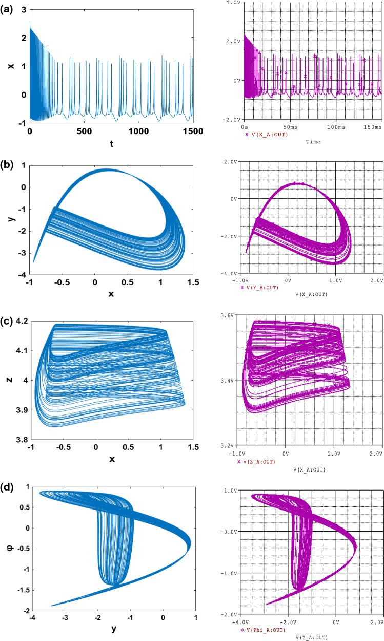
In order to investigate the various important phenomena that the HR model can present under magnetic field effect, we solve system (1) numerically using a fourth-order Runge–Kutta algorithm. It is important to mention that, all results presented in this work, the integration step is always set to Δt = 0.01. Briefly recall that two indicators are generally used to identify chaotic behaviour in a system, we have the bifurcation diagram and the Lyapunov exponent. Indeed, the dynamics of the system is evaluated thanks to the Lyapunov exponent, which is calculated numerically using the algorithm of Wolf et al. (1985). In particular, the sign of the largest Lyapunov exponent determines the rate of almost all the small perturbations of the state variables of the system and, consequently, the nature of the attractor (Tchitnga et al. 2019; Mezatio et al. 2019). When λmax < 0, all disturbances disappear, and trajectories start sufficiently close to each other, thus converging towards the same point of stable equilibrium in the state space. For λmax = 0, initially closed the orbits remain close but discrete, corresponding to the oscillatory dynamics on a limit cycle or a torus. Finally, when λmax > 0 the small perturbations grow exponentially, and the system evolves chaotically, we say in the latter case that the system presents the phenomenon of chaos. When varying the gain k1 that describes the interaction between membrane potential and the magnetic flux of the system (1), bifurcation diagrams of Fig. 1a showing local maxima of the membrane potential x and the corresponding graph of Lyapunov spectrum Fig. 1b of the attractor in terms of the control parameter k1 that is varied in tiny steps in the range 0 ≤ k1 ≤ 1 with the initial condition (− 1.1, − 0.06, 0.04, − 0.08) for , k2 = 0.5 and Iext = 3; other parameters are fixed in previous subsection. For this diagram, it can be observed that, by applying appropriate electromagnetic induction strength, multiple modes in electrical activities of a neuron can be selected. The weak degree of chaos exhibited by the model is clearly justified by the small values of λmax that are always λmax < 0.01. It can be observed that there is an excellent concordance between the bifurcation diagram and the graph of Lyapunov exponents. With some parameter settings in Fig. 2, Time series (Fig. 2a) and various numerical phase portraits (Fig. 2b–d) were produced. These figures demonstrate the chaos mechanism in the system, confirming different bifurcation sequences depicted previously (see Fig. 1).
Fig. 1.
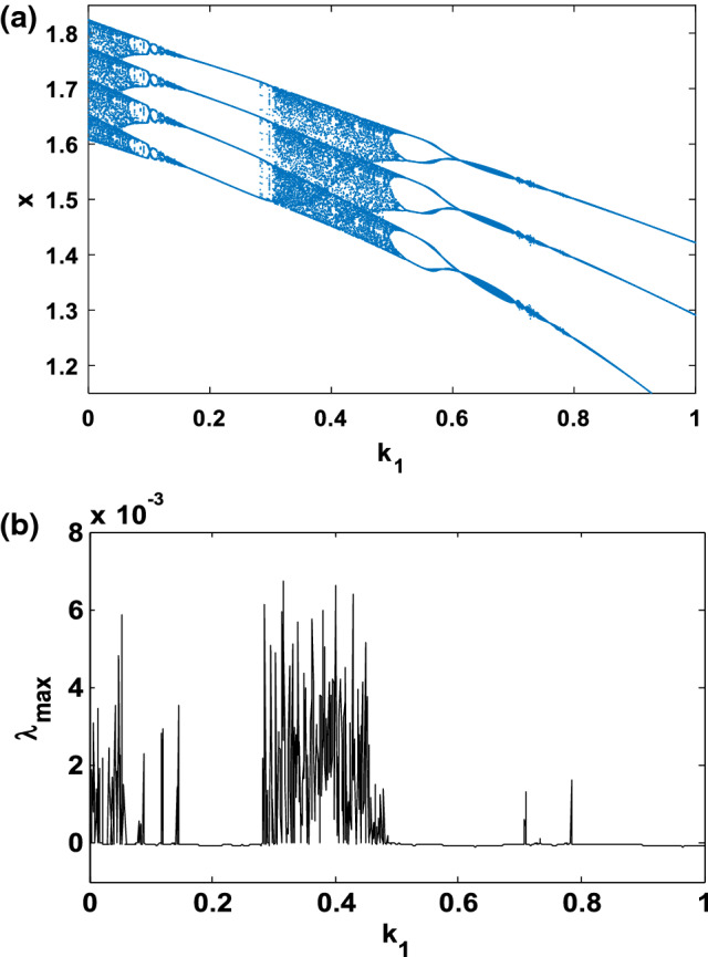
Bifurcation diagram a showing local maxima of the coordinate x of the attractor and corresponding graph of largest Lyapunov exponents (λmax), b versus parameter k1 that is varied in tiny steps in the range 0 ≤ k1 ≤ 1 with the initial condition for . A positive exponent (λmax > 0) indicates chaos while regular states are characterized with negative values of Lyapunov exponent (λmax < 0)
Fig. 2.
Numerical (left) and PSpice simulation (right) of: Time series a, b and two dimensional views c, d of the attractor projected, illustrating the complexity of the system for with the initial condition
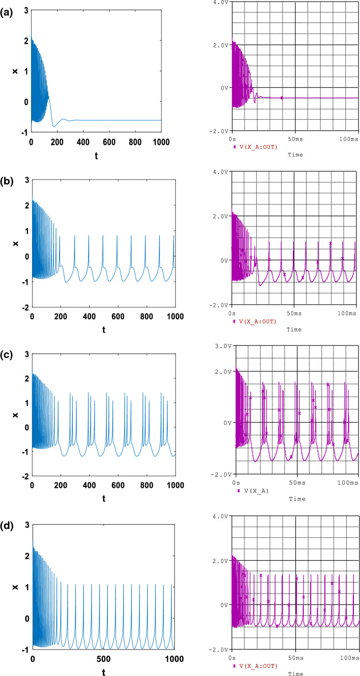
In addition, it is found in Fig. 3 that under different electromagnetic induction strength (k1 and k2) and fixed external current (Iext), quiescent Fig. 3a, spiking Fig. 3b, regular bursting Fig. 3c and periodical states Fig. 3d can be generated from the neuronal circuit with respectively (k1, k2) = (4, 0.5), (k1, k2) = (1.04, 0.31), (k1, k2) = (1, 0.5) and (k1, k2) = (0.4, 0.2).
Fig. 3.
Numerical (left) and PSpice simulation (right) of: The time series of membrane potential in neuron under different electromagnetic induction strength at Iext = 3, α = 0.1, f = 1, β = 0.02, for a k1 = 4 and k2 = 0.5; b k1 = 1.04 and k2 = 0.31; c k1 = 1 and k2 = 0.5; d k1 = 0.4 and k2 = 0.2 with the initial condition
Bifurcation mechanism of bursting firing patterns
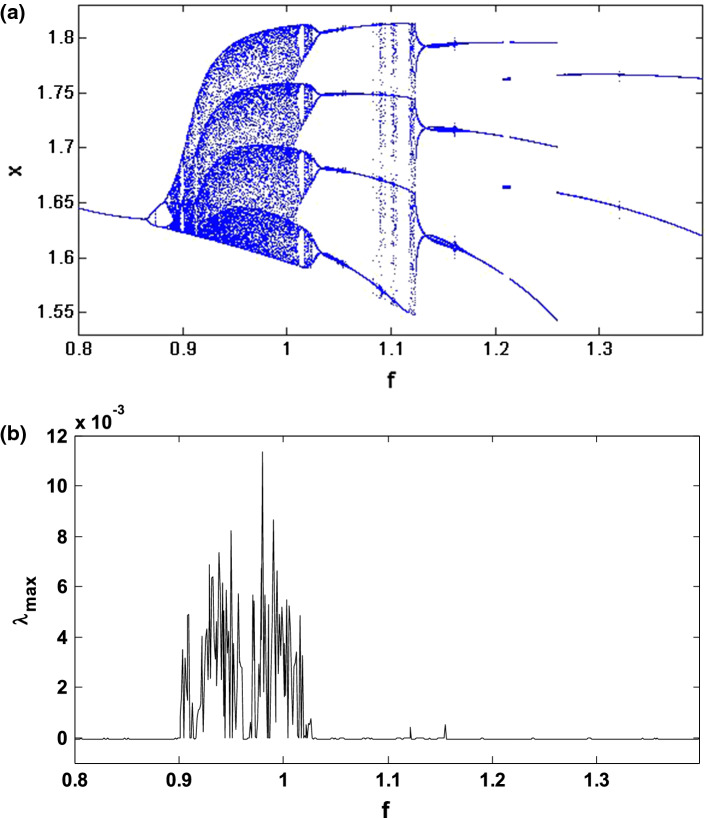
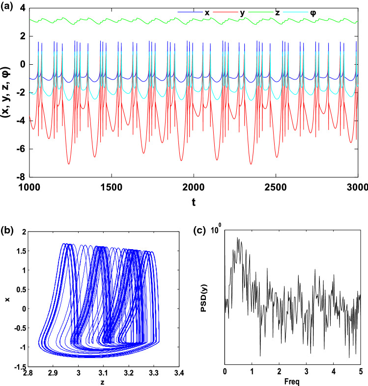
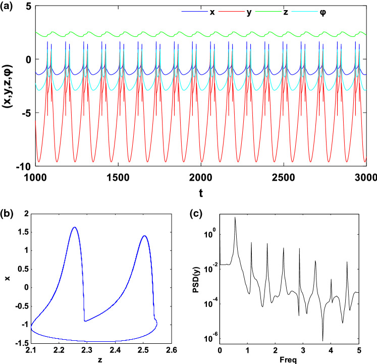
In this subsection, we investigate the bifurcation mechanisms in the mHR neuron model by considering the following specific parameters values: and k2 = 0.5. Briefly recall that the constant f of the system (1) is a significant parameter in the dynamical study of the electrical activity of the neurons because it can make it possible to pass from a bursting behaviour to a spiking behaviour and also to control the spiking frequency. Thus, by varying f in the region [0.8, 1.4] and considering the initial conditions (− 1.1, − 0.06, 0.04, − 0.08), we obtain the bifurcation diagram and the corresponding Lyapunov exponent of Fig. 4. This figure shows that, when f varies, the neuron presents various complex and captivating behaviour such as period, period-doubling cascades, chaos, crisis scenario, reverse period-doubling cascades and periodic window. As an example, let us consider two specific values of f, set as f = 1 and f = 1.35. As predicted by the bifurcation diagram, for these two values, the electrical activity of the neuron has a chaotic bursting firing (see Fig. 5) and periodic bursting firing (see Fig. 6) respectively. Indeed, Figs. 5a and 6a present the time sequences of the four-state variables of the system (1) while Figs. 5b and 6b show the phase portrait in the (z − x) plane for these different states of the neuron electrical activity. In order to confirm the periodic bursting firing (Fig. 5a, b) and the chaotic bursting firing (Fig. 6a, b) of the neuron under the magnetic field effect, the frequency spectra are presented respectively through Figs. 5c and 6c.
Fig. 4.
Bifurcation diagram a showing local maxima of the coordinate x(t) of the attractor and the corresponding 1D largest Lyapunov exponent (λmax) in terms of the control parameter f that is varied in tiny steps in the range 0.8 ≤ f ≤ 1.4 with the initial condition (− 1.1, − 0.06, 0.04, − 0.08)
Fig. 5.
Chaotic bursting firing with f = 1: a Time series of four state variables (x, y, z, φ), b phase portrait in the (z − x) planes and c frequency spectra of the spiking variable (y)
Fig. 6.
Periodic bursting firing with f = 1.35: a Time series of four state variables (x, y, z, φ), b phase portrait in the (z − x) planes and c frequency spectra of the spiking variable (y)
Recall that in neurodynamics, the phenomenon called bursting occurs when the neuron electrical activity alternates between the quiescent state and a repetitive spiking state (Izhikevich 2000). Typically, systems with this type of phenomenon can be subdivided into two subsystems including fast variables and slow variables, implying that these models can display two-time scales and therefore may be subject to the fast–slow bifurcation analysis.
Concerning the model that we study in this work, we can easily notice from Figs. 5a and 6a that, the states variables x, y and φ evolve fastly while the state variable z evolves slowly, which means that, system (1) can be subdivided into a fast subsystem (FS) having x, y, φ as state variables and a slow subsystem (SS) whose only z is a state variable.
Fast–slow bifurcation analysis
Based on the fast–slow analysis (Rinzel 1985), the slow variable z is considered as a parameter for the fast variables x, y, φ and the fast-scale subsystem (FS) is defined by:
| 8 |
For this 3D FS, the equilibrium points are defined by in which is obtained by solving the following equation:
| 9 |
in which, and Using the Cardan method as above to solve Eq. (9), we obtain the following solutions:
| 10 |
where and Δ1 = (q1/2)2 + (p1/3)3.
Similar to what was done previously, if Δ1 > 0 then, Eq. (9) admits a single real root presented by the first equation of Eq. (10), whereas when Δ1 = 0, Eq. (9) admits two real roots presented by the first two equations of Eq. (10). In the latter case (Δ1 < 0) Eq. (9) admits three real roots presented by the three equations of Eq. (10).
In order to study in detail, the consequences that can occur on the stability of the model when the sign of the Cardan discriminant alternates from a positive value to a negative value (and vice versa) passing through zero, we determine the following Jacobian matrix at the steady point EFS.
| 11 |
The characteristic equation corresponding to this Jacobian matrix is thus:
| 12 |
with
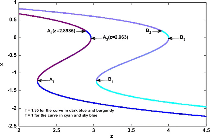
For a 3D ordinary differential equation, the stability conditions obtained by applying the Routh–Hurwitz criteria are: m1 > 0, m1m2 − m3 > 0 and m3 > 0. Since the coefficients mi (i = 1, 2, 3) are real numbers, and they depend on the slow variable z via ( is function of z), we deduce that the stability of the FS also depends on this slow variable. According to the values of these coefficients, it is possible to have several types of bifurcations including a Hopf bifurcation (HBFS) and a fold bifurcation (FBFS). Considering the two specific values of the parameter f used respectively in Figs. 5 and 6 (i.e., f = 1 and f = 1.35), it is observed in Fig. 7 the evolution of the number of equilibrium points in the plane when the slow variable z is modified. From this figure, it can be seen that when the slow variable z increases, the number of equilibrium points also increases from 1 to 2, then from 2 to 3, and thereafter decreases from 3 to 2 and finally from 2 to 1. This sudden transition of the number of equilibrium points justifies the different bifurcations that can be found in the fast–scale subsystem. Indeed, when Δ1 = 0, a small perturbation of the slow variable can cause a degenerate equilibrium point to disappear or to split into two different types of equilibrium points, therefore, fold bifurcation occurs (FBFS). The point FBFS where the fold bifurcation occurs is characterized by the following conditions (Bi et al. 2015; Bao et al. 2019):
Considering these conditions and using Eq. (9), we obtain:
| 13 |
Using the specific parameters’ values defined previously, we obtain:
| 14 |
The point HBFS where the Hopf bifurcation occurs is characterized by the following conditions (Bi et al. 2015; Bao et al. 2019): m1m2 − m3 = 0, (m1 > 0, m3 > 0). Considering these conditions and using Eq. (9), we obtain:
| 15 |
Using the specific parameters’ values defined previously, we obtain:
| 16 |
Figure 8a, b shows the evolution of the Routh–Hurwitz coefficients m1, m3 and m1m2 – m3 when the slow variable z increases for f = 1 (Fig. 8a) and f = 1.35 (Fig. 8b). In these figures, it is easy to observe the values of the slow variable where the conditions for the occurrence of the fold bifurcation FBFS or the Hopf bifurcation HBFS are satisfied. When in the (z – f) plane, f and z respectively vary in the regions [0.8, 1.5] and [2.7, 4.2] as shown in Fig. 8c, there is a Hopf bifurcation at HBFS1 for f = 1.35 and at HFFS2 for f = 1. We also see the occurrence of a fold bifurcation at point FBFS1 for f = 1.35 and point FBFS2 for f = 1. These results are in agreement with the analyzes developed previously and show that when the slow variable increases, we first have a Hopf bifurcation and then a fold bifurcation which implies Hopf-fold bursting.
Fig. 7.
Equilibrium points of the fast-scale subsystem illustrating the different transitions that may justify the possible bifurcations which can occurs in the model. For f = 1 (respectively f = 1.35), the stable equilibrium points are represented by the cyan color (respectively dark blue color) while the unstable equilibrium points are represented in sky blue color (respectively burgundy color). (Color figure online)
Fig. 8.
Curves of the variation of the Routh–Hurwitz coefficients (m1, m3 and m1m2-m3) as a function of the slow variable z for: a f = 1; b f = 1.35. c Fold and Hopf bifurcation sets of the fast-scale subsystem with the z and f evolutions. For (a) and (b), when the conditions m1 > 0, m1m2 − m3 > 0 and m3 = 0 (m1 > 0, m3 > 0 and m1m2 − m3 = 0 respectively) are satisfied, a fold bifurcation (Hopf bifurcation respectively) occurs
Discussion on the bifurcation mechanism of bursting firing patterns
We mentioned at the beginning of this subsection that, bursting occurs when the electrical activity of the neuron alternates between the quiescent state and a repetitive spiking state. Without losing the generality, we choose as an example the value of the parameter f for which the electrical activity of the neuron described by a periodic bursting (i.e. f = 1.35, see Fig. 6). To investigate the bifurcation mechanisms to pass from a quiescent state to a repetitive spiking state in the HR neuron model under the magnetic field effect (see Eq. 1). In Fig. 7, we have two curves, the curve coloured in dark blue and burgundy (respectively cyan and sky blue) represents the variations of the equilibrium point number for f = 1.35 (respectively for f = 1) when the slow variable z evolves. In this figure, the unstable equilibrium points are represented by the areas coloured in burgundy (respectively in sky blue) while the stable equilibrium points are represented by the areas coloured in dark blue (respectively in cyan). It is also observed that the areas where the stability of the equilibrium points is modified are localized by the points A1 (2.249, − 1.19), A2 (2.8985, 0.1959) and A3 (2.963, − 0.001569) [respectively B1 (3.037, − 1.184) B2 (3.9125, 0.191326) and B3 (4, 0) for f = 1). By observing Fig. 8c, we find that the Hopf bifurcation HBFS and the fold bifurcation FBFS appear respectively at points HBFS1 (z = 2.8985, f = 1.35) and FBFS1 (z = 2.963, f = 1.35). Indeed, the occurrence of the Hopf bifurcation at point A2 in Fig. 7 implies that, when a critical value is reached (i.e. at the transition from unstable equilibrium point to stable equilibrium point), the oscillations of the neuron electrical activity die, as a result, the neuron is at rest (quiescent state). The neuron starting from this quiescent state (z = 2.8985), then undergoes a fold bifurcation when z = 2.963, which means that when , the fast-scale subsystem has three equilibrium points among which we have two stable equilibrium points coloured in dark blue and one unstable equilibrium point coloured in burgundy. When z > 2.963, the number of equilibrium points changes, we go from three equilibrium points to briefly two equilibrium points and then to one single stable equilibrium point coloured in dark blue (see Fig. 7). Thanks to the presence of this fold bifurcation, the electrical activity of the neuron will change to give rise to a repetitive spiking and then initiate the next periodic cycle (i.e. alternation between quiescent state and repetitive spiking state). It is, therefore, this mechanism which justifies the periodic bursting that is observed thanks to the time series of the membrane potential x in Fig. 6a. Recall that, these results are also valid for the case where the electrical activity of the neuron is described by a chaotic bursting firing (i.e. f = 1, see Fig. 5) with the only difference that, the alternations between the quiescent state and repetitive spiking state will not be done in a periodic way.
Analog circuit implementation
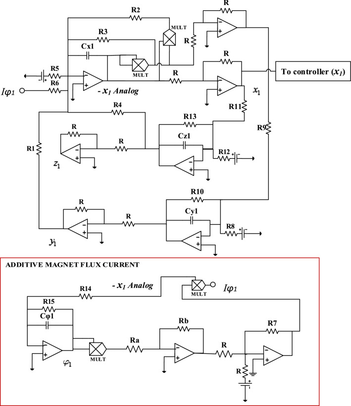
In biophysics, it is essential to propose analog electronic circuits necessary for the construction of some artificial simulators used in the laboratory to carry out certain experiments which cannot be performed on human beings for ethical reasons (Wu et al. 2019). Thus, in Badoni et al. (1995), a method allowing the circuitry realization of an analog attractor neural network with stochastic learning is proposed. Likewise, in Hu et al. (2016), the analog circuit of the Morris–Lecar neuron model is provided to analyze some transitions in the firing activity of neurons. More recently, in Kemwoue et al. (2020), electronic simulations are performed using an analog circuit implementation of the HET cancer model in order to investigate the dynamics of tumor growth. Using this as motivation, in this part of our work, the aim is to be able to set up an analog circuit which will allow us to make a comparison between the theoretical/numerical results obtained previously and the practical results. The circuit diagram that allows us to perform the various simulations in the PSpice software is presented in Fig. 9. The realization of this circuit is carried out with the help of the operational amplifiers TL084 and the associated circuits making it possible to carry out the basic operations like the addition, the subtraction and the integration, the electronic multipliers (MULT) are the analog component versions AD633JN. They are used to implement the non-linear term of the system. By applying Kirchhoff’s laws to the electronic circuit of Fig. 9, their circuit equations are deduced in the following form:
| 17 |
From Eq. (17), we can easily establish the expressions of the parameters of Eq. (1) depending on the value of the electronic components of Fig. 9:
| 18 |
Bearing in mind that the time scaling process offers analog instruments the ability to work with their bandwidths, the unit of time here is 10−4. Indeed, this process offers the opportunity to simulate the behaviour of the system at a given frequency by performing an appropriate time scaling consisting of expressing the MATLAB time variable tM. This concerning the PSpice calculation time variable ts: ts = RCtM = 10−ntM, where n is positive integer depends on the values of resistors and capacitors used in the analog simulation (Kengne et al. 2012).
Fig. 9.
Analog circuit of the modified Hindmarsh–Rose neuron model with additive magnet flux current Iφ = − k1ρ(φ)x. (x Analog denotes the output variable for membrane potential)
The bias is provided by a ± 14 Vdc symmetric voltage source. Setting Cx = Cy = Cz = Cφ = C = 10 nF, and adopting the parameter of system (1) (a, b, c, d, h, r, s, α, β, f, k1, k2, Iext) = (1, 3, 1, 5, 1.6, 0.006, 4, 0.1, 0.02, 1, 1, 0.5, 3), the circuit components in Fig. 9 are selected as follows:
It is worth mentioning that, the effects of varying the modulation gain on membrane potential resulting from induced current (k1) in our mHR neuron model can be analyzed by monitoring the resistors R6 and R7 while keeping the rest of electronic components values constant.
Figures 2 and 3 show the similarities between the numerical simulations (left) and PSpice simulations (right) for different firings patterns of the mHR neuron model (1). From these figures, it appears that for the chosen set of parameters, the system (1) presents strictly multiple modes of electrical activities including quiescent state, spiking, bursting, periodical and chaotic attractors. According to these figures, it is evident that the various behaviours obtained through PSpice simulations are very close to the numerically computed results.
In order to appreciate the physical energy of the electronic circuit of Fig. 9 for the different behaviors of the neuron electrical activity, we present Table 1. To obtain the different values of the energy presented in this table, we calculate the energy of the membrane potential VCx determined by this circuit as well as that of the other variables VCy, VCz and VCφ by the relation where χ = x, y, z, φ and N is the considered points number. Likewise, we deduce the total physical energy of the circuit by the relation . From this table, we note that, when the neuron is at quiescent state, the physical energy of the circuit for the membrane potential variable is the lowest compared to that of the other variables. However, when we consider the total physical energy of the circuit for each of the neuron electrical activities, we see that it is rather the physical energy of the circuit when the neuron exhibits the chaotic behavior that is the weakest.
Table 1.
Physical energy of the electronic circuit used to represent the different electrical activities of the neuron under magnetic flow effect
| Physical energy of the circuit (µJ) | Electrical activity of neuron | ||||
|---|---|---|---|---|---|
| Quiescent state (see Fig. 3a) | Spiking state (see Fig. 3b) | Periodical State (see Fig. 3d) | Regular bursting state (see Fig. 3c) | Chaos or irregular bursting state (see Fig. 2a) | |
| Energy of the membrane potential variable | 7.6004 × 10⁻⁴ | 2.6944 × 10⁻³ | 3.6180 × 10⁻³ | 6.09 × 10⁻³ | 2.9694 × 10⁻³ |
| Energy of the spiking variable | 2.8799 × 10⁻⁴ | 2.3906 × 10⁻² | 4.1014 × 10⁻² | 1.8611 × 10⁻¹ | 2.5391 × 10⁻² |
| Energy of the bursting variable | 8.6103 × 10⁻² | 5.0984 × 10⁻² | 4.1127 × 10⁻² | 2.3698 × 10⁻² | 5.395 × 10⁻² |
| Energy of the magnetic flux variable | 7.5995 × 10⁻² | 2.7089 × 10⁻² | 2.0697 × 10⁻² | 2.2967 × 10⁻² | 1.0185 × 10⁻² |
| Total energy (ET) | 1.6315 × 10⁻¹ | 1.0467 × 10⁻¹ | 1.0646 × 10⁻¹ | 2.3887 × 10⁻¹ | 9.2495 × 10⁻² |
Hopf bifurcation analysis
Throughout this section, we will consider that f = 1. In order to analyze the local bifurcations susceptible to occur in the system (1) when varying the external forcing current Iext and the electromagnetic parameters k1, k2, α, β, we linearize this system around these equilibria E(xe, ye, ze, φe) and the following 4 × 4 Jacobian matrix is obtained:
| 19 |
where J11 = − 3ax2e + 2bxe − k1(α + 3βφ2e), J21 = − 2dxe, J14 = − 6k1βxeφe. The characteristic equation (det (J − λId) = 0, where Id stands as the 4 × 4 identity matrix) corresponding to the above Jacobian matrix can easily be computed as follows:
| 20 |
where
| 21 |
The type of bifurcation occurring at equilibrium points is given in the first point of view by looking at the solution of the characteristic equation of matrix J. In Fig. 10, we show these eigenvalues in the complex plane (Real (λ), Imag (λ)). Indeed, Eq. (20) is solved using the Newton–Raphson method for the following ranges of parameters, 2 ≤ k1 ≤ 4.5, keeping the others constant: α = 0.1, β = 0.02, k2 = 0.5 and Iext = 3. Provided that J is a matrix with real coefficients, complex eigenvalues occur in complex conjugate pairs responsible for the symmetry observed along the real axis. The locus intersects the imaginary axis and thus suggests the possibility of Hopf bifurcation.
Fig. 10.
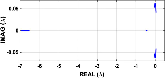
Representation of the eigenvalues solutions of Eq. (20) in the complex plane (real (λ), imag (λ)) for , while keeping . Provided that J is a real matrix, complex eigenvalues occur in complex conjugate pairs responsible of the symmetry observed along the real axis. The locus intersects the imaginary axis and thus suggests the possibility of Hopf bifurcation
Local stability and existence of Hopf bifurcation
After having proved the possible existence of the Hopf bifurcation in the system (1) for a particular range of the parameter, it is essential to be interested in the instability related to this type of bifurcation. Indeed, thanks to Fig. 10, we can deduce some observations concerning the stability of fixed points and bifurcations likely to appear in the model submitted to our study. Looking at the evolution of the eigenvalues of the Jacobian matrix of the system, we note that there is a type of instability which describes well the phenomenon of the Hopf bifurcation: intersection place with the imaginary axis where two conjugated complexes eigenvalues cross the imaginary axis simultaneously. We also note that real solutions are always negative.
In order to prove the occurrence of Hopf bifurcation in our mHR oscillator, we will verify if the transversality condition stated in Hassard et al. (1982), Guckenheimer and Holmes (1983) and Wouapi et al. (2019) is satisfied. For these purposes, and by considering the electromagnetic induction strength k1 as a control parameter, we consider the derivative of the characteristic equation (Eq. 20) with respect to k1:
| 22 |
where
We suppose that Eq. (20) has a pure imaginary root . By substituting it into Eq. (22) and separating imaginary and real parts give:
| 23 |
and
| 24 |
Examining these relations, we see that . Under the restriction that ℜ(λj(k1c) < 0) for j = 3, 4, the second condition for a Hopf bifurcation is met and the Poincaré–Andronov–Hopf theorem holds. Then, Hopf bifurcation can occur at (E, k1c) of system (1).
Obviously, Eq. (20) has a pair of purely imaginary conjugate roots λ1,2 = ±iω0 and a strictly negative reals roots . Our aim now is to deduce a relationship between system’s parameters corresponding to this bifurcation around the equilibrium E(xe, ye, ze, φe). Thus, we substitute λ = iω0 into the Eq. (20) and we obtain the following conditions:
| 25 |
and
| 26 |
To obtain the control parameter’s values k1c, we replace in Eq. (26) a1, a2, a3 and a4 by their expressions described in (21). Hence, after some algebraic manipulations, we derive the following equation from which solutions give k1c:
| 27 |
where and are described in the “Appendix 1” Eqs. (45–48).
Consequently, the following conclusion can be made, when k1 passes through the critical value k1c, system (1) undergoes a Hopf bifurcation at the equilibrium E(xe, ye, ze, φe).
Direction and stability of bifurcating periodic solutions
In this part of this work, we apply the normal form theory (Hassard et al. 1982; Guckenheimer and Holmes 1983; Wiggins 1990; Kuznetsov 1998) to study the direction, stability and period of bifurcating periodic solutions for system (1). The eigenvectors v1, v3 and v4 associated respectively with
Hence, the matrix is determined as follows:
| 28 |
where
Let us substitute Y = P−1(X − E), and in system (1), where F(X, k1), represents the vector field of such system, E(xe, ye, ze, φe) its equilibria, X(x, y, z, φ) and Y(x1, y1, z1, φ1) are states variables [the inverse matrix P−1 are described in the “Appendix 1” Eq. (49)].
We obtain after some mathematical manipulations the expressions of :
| 29 |
where F1(x1, y1, z1, φ1), F2(x1, y1, z1, φ1), F3(x1, y1, z1, φ1), and F4(x1, y1, z1, φ1) are described in the “Appendix 1” Eqs. (50–53).
Notice that, the fixed point of Eq. (29) is the origin. In the following, we follow firstly the procedures described by Hassard et al. (1978, 1982) and Hassard (1978), to figure out the necessary quantities at k1 = k1c:
Then,
By solving the following equations:
where
in which,
and
One obtains
Furthermore,
Finally, we obtain the main quantities described below:
| 30 |
and the Marsden–MacCracken index is:
Results: According to the fact that system (1) undergoes a Hopf bifurcation at equilibrium point E when parameter k1 passes the critical value k1c, the following properties hold (Megam et al. 2016; Qigui and Meili 2016):
If IM < 0 and μ2 < 0(IM > 0 and μ2 > 0), the Hopf bifurcation is non-degenerate and supercritical with stable limit cycle (subcritical with unstable limit cycle).
If β2 < 0(β2 > 0), the bifurcating periodic solutions are orbitally stable (unstable).
If τ2 > 0(τ2 < 0), the period of bifurcating periodic solutions increases (decreases).
Furthermore, the system has a unique amplitude solution of approximated period:
| 31 |
and the characteristic exponent associated with this solution is
| 32 |
where (with μ2 ≠ 0).
The expression of the bifurcating periodic solution (except for an arbitrary phase angle) is approximated by:
where the matrix P is defined in (28), ; and in which
From these results, we conclude that
| 33 |
where
Numerical and PSpice simulation results
Numerical computations are done in order to illustrate the above theoretical results on the Hopf bifurcation. For this instance, we consider the system (1) with the following values of external forcing current Iext = 3 and the electromagnetic parameters k2 = 0.5, α = 0.1, β = 0.02, from where we obtain one equilibrium point (for this parameter’s values, Δ > 0 for any positive value of k1). Taking into consideration this equilibrium point, the critical value of the electromagnetic induction strength k1 defined as roots of Eq. (27) are: k1c1 = 3.274073708, k1c2 = − 5.21211991 and k1c3 = − 29.85155976. By considering the positive feedback gain k1, only the first parameter is chosen. For this critical value, we obtain the unique equilibrium E(− 0.6353297139, − 1.018219227, 3.858681145, − 1.270659428). We also have two real eigenvalues λ3(k1c) = − 6.723062552, λ4(k1c) = − 0.4504199628 and two pure imaginary ones λ1,2(k1c) = ± i0.06254412851.
Furthermore,
then the transversality condition is satisfied. Moreover, the various useful coefficients for the direction of the bifurcation are:
Finally, we obtain the main results: μ2 = − 1.209821043 < 0; β2 = − 0.02471301506 < 0; τ2 = 2.135717548 > 0 and IM = − 0.09225947083 < 0.
Based on the above analysis (IM < 0 and μ2 < 0), it is obvious that the Hopf bifurcation is supercritical and non-degenerate. Hence, the unique equilibrium E(xe, ye, ze, φe) of system (1) is stable when k1u > k1c and the equilibrium loses its stability and a Hopf bifurcation occurs when k1 drops below . As , the bifurcating periodic solutions are asymptotically stable orbits with a period given approximatively by:
and the corresponding characteristic exponent is
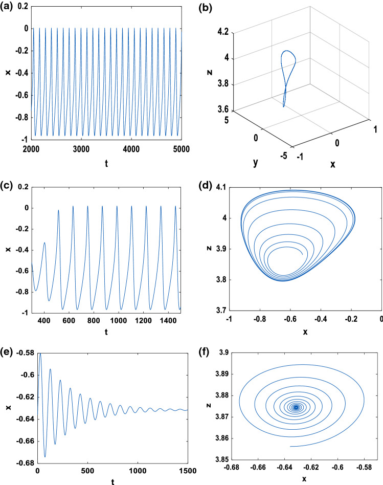
The bifurcating periodic solution is presented for in Fig. 11a, b and we observe that it is orbitally stable. For k1l < k1c, Fig. 11c illustrates that in the domain [k1l, k1c[, the origin is an unstable focus surrounded by a stable limit cycle for which the amplitude increases with . However, for k1u > k1c, in the domain [k1c, k1u[, Fig. 11e, f shows that the origin is a stable focus. The experimental results on PSpice in Fig. 12 also exhibit a good qualitative agreement between the experimental realizations and the numerical simulations.
Fig. 11.
Time series and phase portrait of system (4) with the initial condition while keeping . a, b for k1c = 3.2750; c, d for k1l = 3.2 < k1c; e, f for k1u = 3.4 > k1c
Fig. 12.
Time series and phase portrait of system (4) with the initial condition while keeping constant the other parameter using PSpice simulations. a, b For k1c = 3.2750; c, d for k1l = 3.21 < k1c; e, f for k1u = 3.39 > k1c
Optimal synchronization
Problem statement
In practice, the evolution of the electrical activity of the brain via the neurons is usually represented by a signal called electroencephalogram (EEG). Previous research has shown that this signal can have deterministic characteristics that can be likened to the Lorenz butterfly effect (deterministic chaos). Panahi and collaborators relevant works have shown that a healthy brain has a neuronal activity that is described by a chaotic EEG (Panahi et al. 2017). In the same way, the authors have demonstrated that, when the brain presents some pathology such as epilepsy, the EEG signal obtained is not chaotic but rather periodic. Considering all these results, our goal in this section is to propose through the optimal synchronization approach, a technique to force a sick neuron to have chaotic behaviour in order to correct an abnormality such as epilepsy. Recall that, since the brain is made up of billions of neurons, this technique is just a small example (because we consider only two neurons) which, thanks to future research (notably on the synchronization of neural networks), could be of considerable contribution. Thus, by a judicious choice of the parameters of the system (1), we consider two neurons, the first neuron that we assume as the master is healthy (that is to say, it has a chaotic behaviour). While the second neuron that we assume as the slave is sick (that is to say, it has a periodic behaviour). Our challenge now is to ensure that these two neurons have chaotic behaviour while optimizing the synchronization time.
The equation system of the healthy neuron considered as the master is as follows:
| 34 |
where X1 = (x1, y1, z1, φ1)T are state variables.
The equation system of the epileptic neuron considered as the slave is as follows:
| 35 |
where X2 = (x2, y2, z2, φ2)T are state variables and u is the feedback coupling. The synchronization error e = (e1, e2, e3, e4)T between the healthy neuron and the epileptic neuron is as follows:
| 36 |
Starting from there, it comes out the system below, which makes it possible to describe the error dynamics:
| 37 |
where ΔG is a smooth vector field defined as follows:
The synchronization problem that arises at this level amounts to ensuring that the error dynamics of Eq. (37) is asymptotically stable. In other words, feedback coupling should be powerful enough to provide overall stability of the error dynamics between the healthy neuron and the sick neuron after a finite time T, i.e.
| 38 |
In order to be able to satisfy the conditions of Eq. (38), let ζ1 = e2, ζ2 = e3 and ζ3 = e4. Then, system (37) can be changed into a canonical form (Bowong and Moukam 2004; Femat et al. 1999; Gonzalez et al. 1999) as follows:
| 39 |
where ye denotes the output of system (37), is the unobservable state vector (internal dynamics). The function Θ(e1, ζ, u) is uncertain and is given by:
However, the feedback coupling is function of e1 because it is the only variable that we choose as the output variable ye = e1. Due to the presence of the uncertain term Θ(e1, ζ, u), we perform in the system (39), a change of variable by following (Bowong and Moukam 2004; Femat et al. 1999; Gonzalez et al. 1999) and by letting η = Θ(e1, ζ, u). So, this system is rewritten as follows:
| 40 |
where
At this level, we are trying to show that, when e1 = 0, the zero dynamics subsystem tends asymptotically to the origin, which implies that the system (37) is minimum phase (i.e. the closed-loop system is internally stable). For this, we can prove that, and converge to the origin when e1 = 0.
Noting that ζ = (ζ1, ζ2, ζ3)T is bounded, the zero dynamic is written as follows:
where
Using the Routh–Hurwitz stability criterion, this zero dynamic is asymptotically stable (since r > 0 and k2 > 0). As a consequence on the error dynamics system (37), it is observed that, when the minimum phase property is satisfied, that is to say Ψ(e1, ζ) → Ψ(0, ζ) → 0 as t → ∞, the minimum phase character is observed, that is to say limt→Te1(t) = 0.
In order to achieve a synchronization which minimizes the energy consumption and which optimizes the synchronization time, we use for the following, the optimal controller defined in the “Appendix 2” (see Eq. 74) by:
| 41 |
where k is a strictly positive constant, the root couple and which represent respectively the approximate values of e1 and η are obtained thanks to the following high-gain observer (Kountchou et al.2016; Bowong and Moukam 2004; Gonzalez et al. 1999; Korobov et al. 1993):
| 42 |
In which, L is a strictly positive parameter generally called high-gain parameter. Note that, it is not physically possible to determine the exact value of η therefore of e1. However, to solve this problem, it is preferred to use the high-gain observer defined by Eq. (42) to reproduce the main characteristics of e1 and η through the approximate values and . Finally, thanks to Eq. (40), we reconstruct the dynamics of the variable e1 as well as that of the uncertain variable η from the output ye = e1. Indeed, several recent works have shown that, when the high-gain parameter is more significant than a threshold value (L > L*), the dynamics of the error estimation system (42) converge exponentially to zero (see Gauthier et al. 1992), which implies that, the closed-loop system is stable (Bowong and Moukam 2004; Femat et al. 1999; Gonzalez et al. 1999). Besides, as demonstrated in the “Appendix 2”, the synchronization time associated with the robust controller of Eq. (41) is determined by:
| 43 |
Numerical simulation
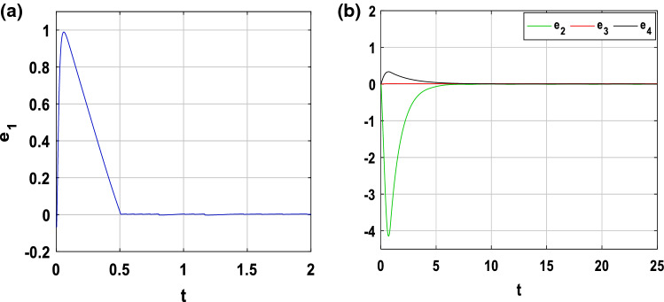
In order to show the feasibility and efficiency of the optimal controller chosen to force a sick neuron (slave system) to follow the electrical activity of a healthy neuron (master system), numerical simulations are performed. The parameters of healthy neuron are those shown in Fig. 2a and those of the sick neuron are shown in Fig. 3d. In other words, the parameters of the master system are as follows (a, b, c, d, h, r, s, α, β, f, k1, k2, Iext) = (1, 3, 1, 5, 1.6, 0.006, 4, 0.1, 0.02, 1, 1, 0.5, 3), while those of the slave system are (a, b, c, d, .h, r, s, α, β, f, k1, k2, Iext) = (1, 3, 1, 5, 1.6, 0.006, 4, 0.1, 0.02, 1, 0.4, 0.2, 3). The initial conditions are chosen to ensure that the healthy neuron will keep its chaotic behaviour while the sick neuron will also keep its periodic behaviour: and . By choosing L = 500 and using Eq. (43), the synchronization time is for k = 2 and . Through Fig. 13, we observe the time sequences of the synchronization error between the healthy neuron and the epileptic neuron. This figure shows that the error dynamics is stabilized at the origin, as a result, the two neurons evolve chaotically after a synchronization time. Especially for Fig. 13a, it is clear that the membrane potentials of the two neurons converge around 0.561094748 s, which corresponds to the finite horizon. The captivating effect of the minimum phase character is shown in Fig. 13b, where it is clear that the other synchronization errors e2, e3 and e4 also stabilize at the origin although the feedback coupling applied only to the state variable e1.
Fig. 13.
Time evolution of the synchronization error. a e1 = x2 − x1 and b e2 = y2 − y1, e3 = z2 − z1 and e4 = φ2 − φ1
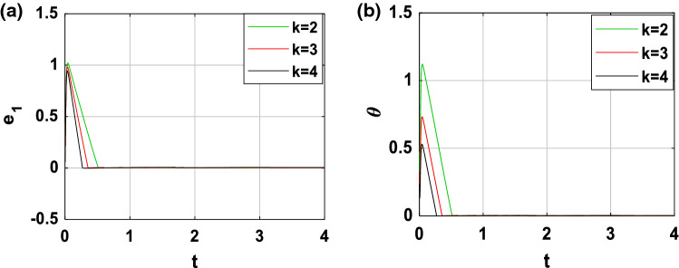
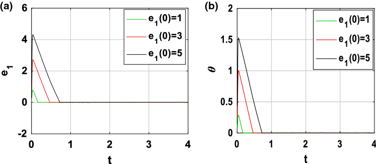
In order to show the robustness of the feedback coupling between the two neurons, we perform more simulations. Indeed, as mentioned previously (see Eq. 43), the synchronization time depends on the control gain k and the initial condition . When , Fig. 14 shows the time evolution of the variable e1(t) as well as that of the controllability function for three different values of k (k = 2, k = 3 and k = 4). We deduce from Fig. 14a that, the convergence of the synchronization error is established after a finite horizon estimate respectively in about 0.5611 s, 0.3558 s and 0.2692 s. From these values and thanks to Fig. 14b, it is evident that, when the control gain k increases, the synchronization time decreases. Moreover, by carrying out a similar study for k = 6, Fig. 15 presents the time series of the variable e1(t) as well as that of the controllability function for three different values of ( and ). It is clearly seen in these figures the opposite effect, that is to say, when increases, the synchronization time also increases.
Fig. 14.
Time evolution of a synchronization error state e1 and b controllability function performed for three different values of the control gain k when
Fig. 15.
Time evolution of a synchronization error state e1 and b controllability function performed for three values of when k = 6
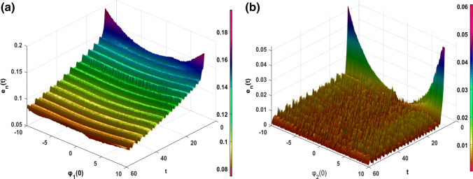
Recent research has shown that in memristor systems, the associated memory effect can lead to a great dependence of the output variables on their initial values (Wu et al. 2018). Consequently, the synchronization between two coupled oscillators can be influenced by the variation of the initial value of the variable associated with the memristor (i.e. the magnetic flux φ(t) in our case). Therefore, to quantitatively assess the sensibility of the initial conditions of the magnetic flux variables φ1(0) and φ2(0) on the performed synchronization approach, we define the following synchronization error norms . From Fig. 16a, b, we can observe that after the transient period, the variation of the initial conditions of the magnetic flux variables φ1 (0) and φ2 (0) have a very weak influence on the synchronization phenomenon between the two coupled neurons (en(t) < 1). This is largely justified by the used synchronization strategy/scheme, in particular through the robustness of the used control law (see “Appendix 2”) and the observed minimum phase character (i.e. the asymptotic convergence towards the origin of the zero dynamics subsystem (ζ1, ζ2, ζ3). In addition, briefly recall that for some dynamic systems, by only modifying the initial conditions of the state variables, this causes the switch from one attractor to another attractor in the phase space (e.g. from a chaotic attractor to a periodic attractor or vice versa). This phenomenon is known as the coexistence of attractors (Njitacke et al. 2019a, b). However, for the range of parameter that we have used in this work, this phenomenon has not been observed, this may further support the low sensitivity related to the initial conditions of the magnetic flux variables in the unidirectional synchronization process between the coupled neurons.
Fig. 16.
Time evolution of error norm when varied the initial value for magnetic flux variable of the a healthy neuron φ1(0) and b the sick neuron φ2(0)
Circuit design and PSpice verification
The main objective here is to implement an electronic circuit that can carry out the synchronization strategy proposed above to verify the effectiveness and practical feasibility of this method. For this, we use the parameters’ values defined in the subsection above to determine, using Eq. (18), the values of the equivalent electronic components. Also, in Figs. 17, 18 and 19, the electronic circuits of the complete master–slave–controller systems are presented, respectively. The implementation of the nonlinear controller parameters is performed using the following relation:
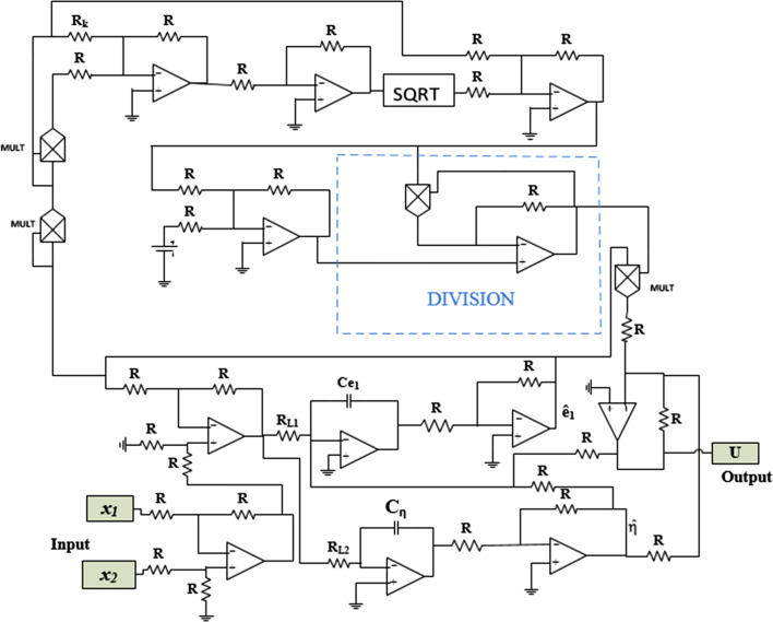
The equivalent of the square root function that appears in Eq. (41) is realized electronically thanks to the bloc ‘SQRT’ that we see in Fig. 19. Considering the synchronization time obtained previously through the Matlab numerical simulation (i.e. for k = 2 and ), we can deduce the equivalent synchronization time for a PSpice simulation thanks to the following relation:
| 44 |
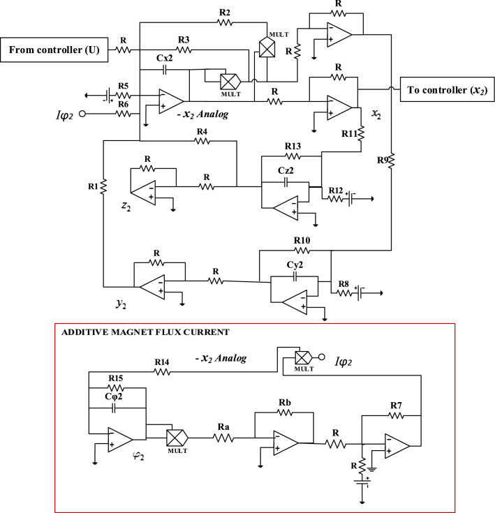
where TS and TM are respectively, the established synchronization time through PSpice simulations and Matlab numerical simulations. We have chosen R = 10 kΩ and C = 10 nF. We can remark that, by monitoring the resistor Rk and voltage Vk, the effects of varying parameter k on the finite horizon can be analysed. Assume that the initial conditions of the master system, slave system and feedback coupling were respectively chosen to be, and . The circuit component values of the feedback coupling were chosen to be and Rk = 2.5 kΩ. The voltage source is set at ± 18 Vdc.
Fig. 17.
Electronic circuit of the drive system (34)
Fig. 18.
Electronic circuit of the response system (35)
Fig. 19.
Circuit diagram of the feedback coupling (41)
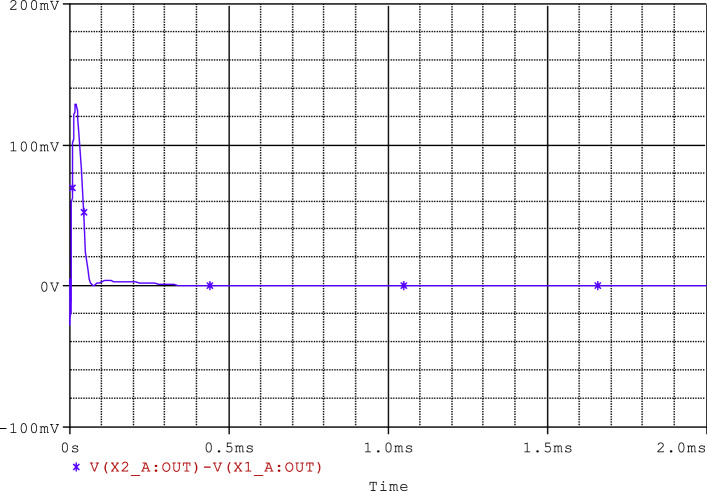
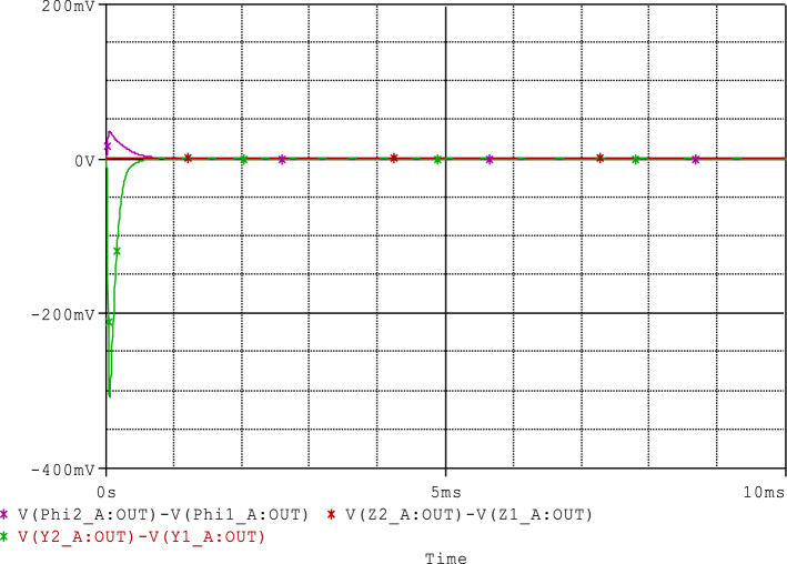
The PSpice simulations results illustrating the optimal synchronization of the two coupled neurons are presented in Figs. 20 and 21. From these results (see Fig. 20), it can clearly be seen that the synchronization time obtained via the PSpice simulation is about 60 μs, which corresponds to the finite horizon. Moreover, in Fig. 21, it is clear that the other synchronization errors e2, e3 and e4 also stabilize at the origin. As a result, we can say that the synchronization method/strategy presented throughout this part of our work is physically feasible and can be used in medical engineering as a new paradigm for treating epilepsy.
Fig. 20.
Time evolution of the synchronization error e1 = x2 − x1 using PSpice simulations
Fig. 21.
Time evolution of the synchronization errors e2 = y2 − y1, e3 = z2 − z1 and e4 = φ2 − φ1 using PSpice simulations
Conclusion
This paper has studied the dynamics and the optimal synchronization of the Hindmarsh–Rose neuron model under magnetic flow effect (mHR). We first studied some collective behaviours of the model. The bifurcation analysis, Lyapunov spectrum and time series have revealed rich and striking phenomena, including various firings patterns by applying appropriate magnetic strength and Hopf-fold bursting through fast–slow bifurcation. More interestingly, we have discovered that non-degenerate Hopf bifurcation occurs in this system when an appropriate chosen magnetic flux varies and reaches its critical value. Furthermore, the direction of the Hopf bifurcation and stability of the bifurcating periodic solutions are analyzed in detail by using Hassard algorithm. We have found an excellent agreement between the results obtained using the electronic circuit and numerical simulation of the system. Later, the synchronization between two mHR neurons models was addressed to propose a new paradigm in the treatment of epilepsy. An optimal robust control scheme using the controllability functions method has been investigated. Then, in other to take into account the behaviour of transient response and the feedback coupling effort (i.e. the energy wasted by the feedback coupling action), we have proposed a robust feedback coupling. The proposed strategy allows setting the time horizon accurately for the synchronization of two mHR. Both numerical and PSpice simulations are presented to show the effectiveness and feasibility of the proposed synchronization scheme.
Acknowledgements
The authors thank the reviewer for their multiple advices which helped to improve this work. WKM especially thanks Patrick Louodop, Romaric Kengne, Anicet Mezatio and Lawrence Gninzanlong for valuable and instructive exchanges.
Appendix 1: Some mathematical expressions concerning the Hopf bifurcation analysis
Some mathematical expressions obtained during calculus are presented here.
| 45 |
| 46 |
| 47 |
| 48 |
| 49 |
in which,
where
| 50 |
| 51 |
| 52 |
| 53 |
Appendix 2: Design procedure for the optimal control law of Eq. (41)
The optimal control problem of the error dynamic system (37) is considered as
| 54 |
| 55 |
for which the objective is to minimize the functional
| 56 |
where are symmetric matrices (assumed as a suitable positive constants here), k is a strictly positive constant gain, t0 ≥ 0 is the time at which the synchronization behavior starts and T ≥ t0 is the time at which the error dynamics system (37) perform the desired trajectory (e = 0). This functional (i.e. Eq. 56) is considered to be a mixed cost function (Korobov et al. 1993). The major challenge now is to find an optimal positional control in feedback form for the error dynamics system of Eq. (37) with a mixed cost functional. In order words, the goal is to find a function u = u(e1), such as:
- , the root of the Cauchy problem
exists on some interval and is unique.57 58 The couple (e1(t), u(e1(t))) is the root of the optimal control problem (54–56).
For these purposes, the controllability function (i.e. robust optimal control law) is designed as follows:
| 59 |
where be a continuous strictly positive function, and solution of the Cauchy problem (57) for the Riccati equation below:
| 60 |
Let us introduce, for T > 0 and , that
| 61 |
| 62 |
We remark that, at each achieves its minimum. Indeed, the function v(T, e1) is continuous and analytic on . As ‖N(T)‖−1‖e1‖ < (N−1(T))e21 and limT→+0‖N(T)‖ = 0, thus limθ→+0v(θ, e1) = +∞, which means that limT→+∞v(T, e1) = +∞, thus, the statement is verified.
We are referring to the function that is defined for e1 ≠ 0 by equality of Eq. (56) and defined for e1 = 0 by Eq. (59) with θ(0) = 0 as the controllability function (Korobov et al. 1993). For any e1 ≠ 0, the value of this function corresponds to the minimal positive solution of the equation υ(θ, e1) = 0, at which v(θ, e1) = 0 achieves its global minimum (see Korobov et al. 1993). Thus, the finite time horizon T is given by expression of θ(e1(0)) which is deduced by solving the equation υ(θ, e1) = 0.
In the sequel, we give some main properties of the controllability function θ(e1) as mentioning in (Korobov et al. 1993).
Property 1
From θ(e1) → 0, it follows that e1 → 0.
Indeed,
| 63 |
Thus,
| 64 |
From Eqs. (63) and (64), we have
| 65 |
Let us consider any positive number μ such that
| 66 |
Letting ℓ > 0 such that, if 0 < θ(e1) < ℓ, then ‖N(θ(e1))‖ < μ; that is ‖N(θ(e1))‖−1 > 1/μ. Then, when 0 < θ(e1) < ℓ, using Eqs. (65) and (66), one obtains:
| 67 |
Since Eq. (67) is satisfied, property 1 is fulfilled.
Property 2
When θ(e1) → 0, then v(θ(e1), e1) → 0.
Suppose any positive number μ and choose μ > ℓ > 0 so small that when θ(e1) < ℓ, N−1(μ)e21 < μ. Then v(θ(e1), e1) ≤ v(μ, e1) = (k2 + 1)μ, which justifies the second property.
Property 3
For any initial condition for every t ∊ [0, θ(e1(0))](see Korobov et al. 1993for the proof of Property 3).
Proposition 1
Let θ(e1) be the controllability function, under the optimal control law (59), the synchronization error e1(t) converges asymptotically to the origin at an established finite time T = θ(e1(0)). Besides, the closed loop performance has a value of the functional (56),
Proof
Considering property 3, the fact that follows from
| 68 |
Assume μ > 0, consider the value of Eq. (56) at the feedback coupling u(e1) and the solution e1(t) corresponding to it, we obtain
| 69 |
This achieves the proof.□
Considering the estimated variables of Eq. (42), the optimal control (59) is
| 70 |
where N is the solution of the Riccati equation (60). Thus, by simply solving this Riccati equation for W = 1 and U = 1, we obtain the following solution:
| 71 |
The expressions of v and υ are
| 72 |
By for θ gives
| 73 |
The other root is discarded because the relation is verified. Finally, the optimal control law is
| 74 |
Footnotes
Publisher's Note
Springer Nature remains neutral with regard to jurisdictional claims in published maps and institutional affiliations.
References
- Abeles M. Time is precious. Sciences. 2004;304:523–524. doi: 10.1126/science.1097725. [DOI] [PubMed] [Google Scholar]
- Arena P, Fortuna L, Frasca M, La Rosa M. Locally active Hindmarsh–Rose neurons. Chaos Solitons Fractals. 2006;27(2):405–412. [Google Scholar]
- Badoni D, Bertazzoni S, Buglioni S, Salina G, Amit DJ, Fusi S. Electronic implementation of an analogue attractor neural network with stochastic learning. Netw Comput Neural Syst. 1995;6(2):125–157. [Google Scholar]
- Bao B, Hu A, Bao H, Xu Q, Chen M, Wu H. Three-dimensional memristive Hindmarsh-Rose neuron model with hidden coexisting asymmetric behaviors. Complexity. 2018 doi: 10.1155/2018/3872573. [DOI] [Google Scholar]
- Bao B, Hu A, Xu Q, Bao H, Wu H, Chen M. AC-induced coexisting asymmetric bursters in the improved Hindmarsh–Rose model. Nonlinear Dyn. 2018;92(4):1695–1706. [Google Scholar]
- Bao H, Hu A, Liu W, Bao B. Hidden bursting firings and bifurcation mechanisms in memristive neuron model with threshold electromagnetic induction. IEEE Trans Neural Netw Learn Syst. 2019 doi: 10.1109/TNNLS.2019.2905137. [DOI] [PubMed] [Google Scholar]
- Bi Q, Ma R, Zhang Z. Bifurcation mechanism of the bursting oscillations in periodically excited dynamical system with two time scales. Nonlinear Dyn. 2015;79:101–110. [Google Scholar]
- Boccaletti S, Latora V, Moreno Y, Chavez M, et al. Complex networks: structure and dynamics. Phys Rep. 2006;424(4–5):175–308. [Google Scholar]
- Boccaletti S, Bianconi G, Criado R, Wang Z, Zanin M, et al. The structure and dynamics of multilayer networks. Phys Rep. 2014;544(1):1–122. doi: 10.1016/j.physrep.2014.07.001. [DOI] [PMC free article] [PubMed] [Google Scholar]
- Bowong S, Moukam KFM. Synchronization of uncertain chaotic systems via backstepping approach. Chaos Solitons Fractals. 2004;21:999–1011. [Google Scholar]
- Chay TR. Chaos in a three-variable model of an excitable cell. Phys D. 1985;16:233–242. [Google Scholar]
- Coombes S, Bressloff PC. Bursting: the genesis of rhythm in the nervous system. London: World Scientific; 2005. [Google Scholar]
- Djeundam SRD, Yamapi R, Kofane TC, Azizalaoui MA. Deterministic and stochastic bifurcations in the Hindmarsh–Rose neuronal model. Chaos. 2013;23:033125. doi: 10.1063/1.4818545. [DOI] [PubMed] [Google Scholar]
- Ermentrout GB, Terman DH. Mathematical foundations of neuroscience. Berlin: Springer; 2010. [Google Scholar]
- Estrada E. The structure of complex networks: theory and applications. Oxford: Oxford University Press; 2012. [Google Scholar]
- Femat R, Alvarez-Ramirez J, Castillo-Toledo B, Gonzalez J. On robust chaos suppression of nonlinear oscillators: application to Chuas circuit. IEEE Trans Circuits Syst-I. 1999;46(9):1150–1152. [Google Scholar]
- Fetz EE. Temporal coding in neural populations? Science. 1997;278:1901–1902. doi: 10.1126/science.278.5345.1901. [DOI] [PubMed] [Google Scholar]
- Fitzhugh R. Impulses and physiological states in theoretical models of nerve membrane. Biophys J. 1961;1(6):445. doi: 10.1016/s0006-3495(61)86902-6. [DOI] [PMC free article] [PubMed] [Google Scholar]
- Gauthier JP, Hammouri H, Othman S. A simple observer for a nonlinear systems applications to bioreactors. IEEE Trans Autom Contr. 1992;37:857–858. [Google Scholar]
- Ge M, Jia Y, Xu Y, Yang L. Mode transition in electrical activities of neuron driven by high and low frequency stimulus in the presence of electromagnetic induction and radiation. Nonlinear Dyn. 2018;91:515–523. [Google Scholar]
- Gonzalez J, Femat R, Alvarez-Ramirez J, Aguilar R, Barron MA. A discrete approach to the control and synchronization of a class of chaotic oscillators. IEEE Trans Circuits Syst-I. 1999;46:1139–1143. [Google Scholar]
- Guckenheimer J, Holmes P. Nonlinear oscillations, dynamical systems and bifurcation of vector field. New York: Springer; 1983. [Google Scholar]
- Hassard B. Bifurcation of periodic solutions of the Hodgkin–Huxley model for squid giant axon. J Theor Biol. 1978;71:401–420. doi: 10.1016/0022-5193(78)90168-6. [DOI] [PubMed] [Google Scholar]
- Hassard B, Wan Y. Bifurcation formulae derived from center manifold theory. J Math Anal Appl. 1978;63:297–312. [Google Scholar]
- Hassard B, Kazarinof N, Wan Y. Theory and application of Hopf bifurcation. Cambridge: Cambridge University Press; 1982. [Google Scholar]
- Hindmarsh JL, Rose RM. A model of the nerve impulse using two first-order differential equations. Nature. 1982;296:162–164. doi: 10.1038/296162a0. [DOI] [PubMed] [Google Scholar]
- Hindmarsh JL, Rose RM. A model of neuronal bursting using three coupled first order differential equations. Proc R Soc Lond B Biol Sci. 1984;21:87–102. doi: 10.1098/rspb.1984.0024. [DOI] [PubMed] [Google Scholar]
- Hodgkin AL, Huxley AF. The dual effect of membrane potential on sodium conductance in the giant axon of Loligo. J Physiol. 1952;116(4):497–506. doi: 10.1113/jphysiol.1952.sp004719. [DOI] [PMC free article] [PubMed] [Google Scholar]
- Hu X, Liu C, Liu L, et al. An electronic implementation for Morris–Lecar neuron model. Nonlinear Dyn. 2016;84:2317–2332. [Google Scholar]
- Innocenti G, Genesio R. On the dynamics of chaotic spiking-bursting transition in the Hindmarsh–Rose neuron. Chaos. 2009;19(2):023124. doi: 10.1063/1.3156650. [DOI] [PubMed] [Google Scholar]
- Izhikevich EM. Neural excitability, spiking and bursting. Int J Bifurc Chaos. 2000;10:1171–1266. [Google Scholar]
- Jia C, Wang J, Deng B, Wei X, Che Y. Estimating and adjusting abnormal networks with unknown parameters and topology. Chaos. 2011;21:013109. doi: 10.1063/1.3539815. [DOI] [PubMed] [Google Scholar]
- Kemwoue FF, Dongo JM, Mballa RN, Gninzanlong CL, Wouapi KM, Mokhtari, et al. Bifurcation, multistability in the dynamics of tumor growth and electronic simulations by the use of PSpice. Chaos Solitons Fractals. 2020;134:109689. [Google Scholar]
- Kengne J, Chedjou JC, Kenne G, Kyamakya K, Kom GH. Analog circuit implementation and synchronization of a system consisting of a van der Pol oscillator linearly coupled to a Duffing oscillator. Nonlinear Dyn. 2012;70:2163–2173. [Google Scholar]
- Kivelä M, Arenas A, Barthelemy M, Gleeson JP, Moreno Y, Porter MA. Multilayer networks. J Complex Netw. 2014;2(3):203–271. [Google Scholar]
- Korobov VI, Krutin VI, Sklyar GM. An optimal control problem with a mixed cost function. SIAM J Contr Optim. 1993;31:624–645. [Google Scholar]
- Kountchou M, Louodop P, Bowong S, Fotsin H. Optimization of the synchronization of the modified Duffing system. J Adv Res Dyn Control Syst. 2014;6:25–48. [Google Scholar]
- Kountchou M, Louodop P, Bowong S, Fotsin H, Saidou Analog circuit design and optimal synchronization of a modified Rayleigh system. Nonlinear Dyn. 2016;85:399. [Google Scholar]
- Kuznetsov YA. Elements of applied bifurcation theory. New York: Springer; 1998. [Google Scholar]
- Li L, Gu H, Yang M, Liu Z, Ren W. A series of bifurcation scenarios in the firing pattern transitions in an experimental neural pacemaker. Int J Bifurc Chaos. 2004;14(5):1813–1817. [Google Scholar]
- Li-Xia D, Qi-Shao L. Codimension-two bifurcation analysis in Hindmarsh–Rose model with two parameters. Chin Phys Lett. 2005;22:1325. [Google Scholar]
- Lu L, Jia Y, Liu W, Yang L. Mixed stimulus-induced mode selection in neural activity driven by high and low frequency current under electromagnetic radiation. Complexity. 2017;7628537:1–11. [Google Scholar]
- Lv M, Ma J. Multiple modes of electrical activities in a new neuron model under electromagnetic radiation. Neurocomputing. 2016;205:375–381. [Google Scholar]
- Lv M, Wang CN, Ren GD, Ma J. Model of electrical activity in a neuron under magnetic flow effect. Nonlinear Dyn. 2016;85(3):1479–1490. [Google Scholar]
- Ma J, Wu F, Wang C. Synchronization behaviors of coupled neurons under electromagnetic radiation. Int J Mod Phys B. 2017;31:1650251. [Google Scholar]
- Ma J, Zhang G, Hayat T, Ren GD. Model electrical activity of neuron under electric field. Nonlinear Dyn. 2019;95(2):1585–1598. [Google Scholar]
- Marco S, Daniele L, De Lange E. The Hindmarsh–Rose neuron model: bifurcation analysis and piecewise-linear approximations. Chaos. 2008;18(3):033128. doi: 10.1063/1.2975967. [DOI] [PubMed] [Google Scholar]
- Megam NEB, Fotsin HB, Louodop FP, Kamdoum VT, Cerdeira AH. Bifurcations and multistability in the extended Hindmarsh–Rose neuronal oscillator. Chaos Solitons Fractals. 2016;85:151–163. [Google Scholar]
- Mezatio BA, Motchongom MT, Tekam BRW, Kengne R, Tchitnga R, Fomethe A. A novel memristive 6D hyperchaotic autonomous system with hidden extreme multistability. Chaos Solitons Fractals. 2019;120:100–115. [Google Scholar]
- Mondal A, Upadhyay RK, Ma J, Yadav BK, Sharma SK, Mondal A. Bifurcation analysis and diverse firing activities of a modified excitable neuron model. Cogn Neurodyn. 2019;13:393–407. doi: 10.1007/s11571-019-09526-z. [DOI] [PMC free article] [PubMed] [Google Scholar]
- Morris C, Lecar H. Voltage oscillations in the barnacle giant muscle fiber. Biophys J. 1981;35:193–213. doi: 10.1016/S0006-3495(81)84782-0. [DOI] [PMC free article] [PubMed] [Google Scholar]
- Njitacke ZT, Kengne J, Fonzin TF, Leutcha BP, Fotsin HB. Dynamical analysis of a novel 4-neurons based Hopfield neural network: emergences of antimonotonicity and coexistence of multiple stable states. Int J Dyn Control. 2019;7:823–841. [Google Scholar]
- Njitacke ZT, Kengne J, Fotsin HB. A plethora of behaviors in a memristor based Hopfield neural networks (HNNs) Int J Dyn Control. 2019;7:36–52. [Google Scholar]
- Panahi S, Aram Z, Jafari S, Ma M, Sprott JC. Modeling of epilepsy based on chaotic artificial neural network. Chaos Solitons Fractals. 2017;105:150–156. [Google Scholar]
- Parastesh F, Rajagopal K, Karthikeyan A, Alsaedi A, Hayat T, Pham VT. Complex dynamics of a neuron model with discontinuous magnetic induction and exposed to external radiation. Cogn Neurodyn. 2018;12:607–614. doi: 10.1007/s11571-018-9497-x. [DOI] [PMC free article] [PubMed] [Google Scholar]
- Parastesh F, Azarnoush H, Jafari S, et al. Synchronizability of two neurons with switching in the coupling. Appl Math Comput. 2019;350:217–223. [Google Scholar]
- Perc M. Optimal spatial synchronization on scale-free networks via noisy chemical synapses. Biophys Chem. 2009;141:175–179. doi: 10.1016/j.bpc.2009.01.012. [DOI] [PubMed] [Google Scholar]
- Pinto RD, Varona P, Valkovskii AR, Szücs A, Abarbanel HD, Rabinovich MI. Synchronous behavior of two coupled electronic neurons. Phys Rev E. 2000;62(2):2644. doi: 10.1103/physreve.62.2644. [DOI] [PubMed] [Google Scholar]
- Qigui Y, Meili B. A new 5D hyperchaotic system based on modified generalized Lorenz system. Nonlinear Dyn. 2016;88:189–221. [Google Scholar]
- Ren G, Xu Y, Wang C. Synchronization behavior of coupled neuron circuits composed of memristors. Nonlinear Dyn. 2017;88(2):893–901. [Google Scholar]
- Rigatos G, Wira P, Melkikh A. Nonlinear optimal control for the synchronization of biological neurons under time-delays. Cogn Neurodyn. 2019;13:89–103. doi: 10.1007/s11571-018-9510-4. [DOI] [PMC free article] [PubMed] [Google Scholar]
- Rinzel J. Ordinary and partial differential equations. Lect Notes Math. 1985;1151:304. [Google Scholar]
- Rostami Z, Jafari S. Defects formation and spiral waves in a network of neurons in presence of electromagnetic induction. Cogn Neurodyn. 2018;12(2):235–254. doi: 10.1007/s11571-017-9472-y. [DOI] [PMC free article] [PubMed] [Google Scholar]
- Sejnowski TJ. Time for a new neural code? Nature. 1995;376:21–22. doi: 10.1038/376021a0. [DOI] [PubMed] [Google Scholar]
- Selverston AI, Rabinovich MI, Abarbanel HDI, Elson R, Szücs A, Pinto RD, et al. Reliable circuits from irregular neurons: a dynamical approach to understanding central pattern generators. J Physiol Paris. 2000;94(5–6):357–374. doi: 10.1016/s0928-4257(00)01101-3. [DOI] [PubMed] [Google Scholar]
- Shi X, Wang Z. Adaptive synchronization of time delay Hindmarsh–Rose neuron system via self-feedback. Nonlinear Dyn. 2012;69:21472153. [Google Scholar]
- Tchitnga R, Mezatio BA, Fonzin Fozin T, Kengne R, Louodop Fotso PH, Fomethe A. A novel hyperchaotic three-component oscillator operating at high frequency. Chaos Solitons Fractals. 2019;118:160–180. [Google Scholar]
- Uhlhaas PJ, Singer W. Neural synchrony in brain disorders: relevance for cognitive dysfunctions and pathophysiology. Neuron. 2006;52(1):155–168. doi: 10.1016/j.neuron.2006.09.020. [DOI] [PubMed] [Google Scholar]
- Valera F, Lachaux JP, Rodriguez E, Martinerie J. The brainweb: phase synchronization and large-scale integration. Nat Rev Neurosci. 2001;2:229–239. doi: 10.1038/35067550. [DOI] [PubMed] [Google Scholar]
- Wang Z, Shi X. Electric activities of time delay memristive neuron disturbed by Gaussian white noise. Cogn Neurodyn. 2020;14:115–124. doi: 10.1007/s11571-019-09549-6. [DOI] [PMC free article] [PubMed] [Google Scholar]
- Wiggins S. Introduction to applied nonlinear dynamical systems and chaos. New York: Springer; 1990. [Google Scholar]
- Wolf A, Swift JB, Swinney HL, Wastano JA. Determining Lyapunov exponents from time series. Phys D. 1985;16(3):285–317. [Google Scholar]
- Wouapi KM, Fotsin BH, Feudjio KF, Njitacke TZ. Hopf bifurcation, offset boosting and remerging Feigenbaum trees in an autonomous chaotic system with exponential nonlinearity. SN Appl Sci. 2019;1(12):1715. [Google Scholar]
- Wouapi KM, Fotsin BH, Louodop FP, Feudjio KF, Njitacke ZT, Djeudjo TH. Various firing activities and finite-time synchronization of an improved Hindmarsh–Rose neuron model under electric field effect. Cogn Neurodyn. 2020;14:375–397. doi: 10.1007/s11571-020-09570-0. [DOI] [PMC free article] [PubMed] [Google Scholar]
- Wu FQ, Ma J, Ren GD. Synchronization stability between initial-dependent oscillators with periodical and chaotic oscillation. J Zhejiang Univ Sci A. 2018;19(12):889–903. [Google Scholar]
- Wu F, Ma J, Zhang G. A new neuron model under electromagnetic field. Appl Math Comput. 2019;347:590–599. [Google Scholar]
- Xu Q, Zhang Q, Bao B, Hu Y. Non-autonomous second order memristive chaotic circuit. IEEE Access. 2017;5:21039–21045. [Google Scholar]
- Xu F, Zhang J, Jin M, Huang S, Fang T. Chimera states and synchronization behavior in multilayer memristive neural networks. Nonlinear Dyn. 2018;94(2):775–783. [Google Scholar]
- Yang Z, Lu Q. Transitions from bursting to spiking due to depolarizing current in the Chay neuronal model. Commun Nonlinear Sci Numer Simul. 2007;12(3):357–365. [Google Scholar]
- Zhu J, Liu X. Measuring spike timing distance in the Hindmarsh–Rose neurons. Cogn Neurodyn. 2018;12:225–234. doi: 10.1007/s11571-017-9466-9. [DOI] [PMC free article] [PubMed] [Google Scholar]


