Abstract
Summary: A data acquisition protocol for postoperative imaging of cochlear implants by using multisection CT (MSCT) is described. The improved image quality of MSCT allows assessment of the precise intracochlear position of the electrode array and visualization of individual electrode contacts. Such images can aid in fitting the speech processor, especially in difficult cases.
Cochlear implantation has become widely available and permits successful treatment of severe or profound sensorineural hearing loss in patients who do not receive adequate benefit from hearing aids. The American Medical Association and the American Academy of Otolaryngology—Head and Neck Surgery have recognized that the cochlear implant is a standard treatment for patients with profound sensorineural hearing loss (1). An electrode array is inserted into the scala tympani for direct electrical stimulation of spiral ganglion cells of the auditory nerve, thereby bypassing damaged hair cells. Postoperative imaging is performed to confirm intracochlear positioning and integrity of the electrode array and detection of electrode kinking. Plain radiographs, which are inexpensive and not difficult to obtain, are most commonly used for this assessment.
New insights into the mechanism of electrical stimulation that produces hearing have led to new developments in electrode design. The new generation of cochlear implants is designed to be in a perimodiolar position rather than lying along the outer wall of the cochlea. The precurved design of perimodiolar electrodes (also called “modiolus-hugging” electrodes) brings the electrode contacts somewhat closer to the modiolus and thus closer to the spiral ganglion cells than earlier straight designs that follow the outer wall of the cochlea. The closer proximity of the contacts to the nerve fibers to be stimulated is believed to have beneficial effects on stimulus thresholds, power consumption, spatial selectivity, and dynamic range (2). Thus, there is a growing interest in precisely documenting the position of the individual electrode contacts in relation to cochlear structures and the insertion depth of the electrode array. Another important issue is the documentation of potential insertion trauma, such as perforation of the basilar membrane, which may lead to degeneration of neuronal elements and scar or bone formation within the cochlea.
Several imaging techniques have been described to achieve this goal in both temporal bone studies and clinical practice. They include conventional radiography (“cochlear view”) (3), (video) fluoroscopy (4, 5), phase-contrast radiography (6), cone beam CT (7), fusion of conventional radiographs and CT images by using either electrodes as fiducial markers (8) or stereophotogrammetry (by using a stereo pair of radiographs to compute the 3D locations of individual electrodes) (9), and spiral CT (10).
Conventional radiography can resolve each electrode contact, but it cannot provide 3D details. Whereas conventional radiography is based on absorption contrast, phase-contrast radiography is based on phase or refraction effects. A microfocus radiographic tube source is used to ensure a sufficiently high level of spatial coherence of the radiograph. Large projection distances allow further wave propagation and interference effects to occur, resulting in observable changes in intensity (phase contrast) in the image plane. The images provide better visualization of anatomic details of the inner ear and of the structure of the electrode array (7). Both phase-contrast radiography and cone beam CT, however, have been used successfully in vitro only and are not likely to be clinically relevant alternatives in the near future. The main disadvantage of CT in the postoperative assessment of a cochlear implant is image degradation by partial voluming and metallic artifacts rendering individual electrodes indistinguishable (3, 8–10). By using multisection CT (MSCT), we produced in vivo images of cochlear implants on which individual electrode contacts can be distinguished. To the best of our knowledge, this is the first report of postoperative imaging of cochlear implants with such spatial detail made on a commercially available clinical scanner.
Imaging Technique
Data acquisition was performed on a MSCT imaging scanner (Aquilion 4, Toshiba Medical Systems Europe; Zoetermeer, the Netherlands) by using the following parameters: four times 0.5-mm section thickness; 0.5 seconds rotation time; 0.75 pitch factor; 120 kV tube voltage; 150 mA tube current; and a 240-mm scan field of view (FOV). Images with a nominal thickness of 0.5 mm were reconstructed by using a 0.3-mm reconstruction increment, 90-mm reconstruction FOV, 512 × 512 matrix, and high-resolution reconstruction algorithm (FC81). The radiation risk of the CT scan is best expressed by the effective dose. The effective dose of the used CT acquisition is about 0.8 mSv, which is well below the annual radiation exposure from natural sources. The dose to the eye lens is of no major concern. The estimated threshold for visual impairment (cataract) of the lens in the average human adult, expressed as the absorbed dose in the eye lens, is 5 Sv for a single exposure and 8 Sv for fractionated exposures (11). Even repeated diagnostic CT scans do not approach such high levels of absorbed dose to the eye lens. The voxels produced with this technique are practically isotropic (voxel size, 0.47 × 0.47 × 0.50 mm), which allows reformations in any plane with virtually no loss in resolution. The images were transferred to a workstation running a software package for postprocessing (Easy Vision; Philips, Best, the Netherlands) to generate 2D reformations and 3D reconstructions. Multiplanar reconstructions (MPRs) through the cochlea were made parallel to the basal turn of the cochlea and perpendicular to the modiolus and thus in the plane of the electrode array. A second set of MPRs was made perpendicular to the basal turn and parallel to the modiolus rendering coronal images of the scala tympani and vestibuli. These images might be helpful in the assessment of insertion trauma to the basilar membrane. Three-dimensional reconstructions were made by using a volume-rendering (VR) technique. Window width and window level were adjusted until both the cochlear tissues and the individual electrodes could be visualized.
Case Reports
Case 1
A 2.5-year-old girl with normal language development developed sudden profound sensorineural hearing loss following bacterial meningitis. She did not benefit from hearing aids, and within 6 months she presented with a delay in language development of 10–16 months. MR imaging and CT scanning of the temporal bone were performed. Partial obliteration of the cochleovestibular system due to ossification, more pronounced on the right side than on the left side, was seen. The diagnosis of ossifying labyrinthitis was made. On the basis of these findings, the patient was selected for cochlear implant surgery in the left ear.
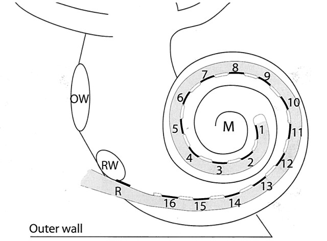
Peroperatively fibrous and osseous tissue was removed from the scala tympani, and after several attempts, a Clarion CII cochlear implant (Advanced Bionics Corp., Sylmar, CA) with Hifocus I electrode array (Fig 1) was fully inserted. The electrode array was brought into a perimodiolar position by secondary insertion of a so-called positioner, which could not be completely inserted.
Fig 1.
Schematic representation of a HiFocus I (Clarion CII Bionic ear) electrode array, which is inserted into the scala tympani via a cochleostomy near the round window niche (RW). The electrode array has a reference electrode (R) and 16 equidistantly spaced contacts (black lines), numbered from the tip of the electrode array to the basal end, which are facing the modiolus (M). They are positioned on a silastic carrier (gray) and are separated by silastic blebs (white lines). The oval window (OW) and outer wall of the cochlea (outer wall) are indicated.
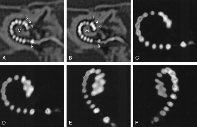
Postoperative MSCT imaging was performed immediately after the surgery under the same anesthesia as used for the surgery. MPRs and volume-rendered images showed kinking of the tip of the electrode array (Fig 2). Accordingly, the two most distal contacts were deprogrammed to anticipate problems in mapping. Because mapping of a cochlear implant is done on a subjective basis, which is difficult to obtain in children of this age, imaging provided essential information to optimize the function of the cochlear implant. Two years after the implantation, the girl’s oral language development is within the range of normal for her age.
Fig 2.
Case 1. A and B, Oblique MPRs of high-resolution MSCT images in the plane of the electrode array demonstrate 16 electrode contacts within the scala tympani. The tip of the electrode (contacts 1–3) projects cranial to contacts 4–6, indicating kinking of the electrode array. C–F, 3D VR images confirm this finding. On conventional radiography (cochlear view) electrode contacts 1–6 would be superimposed on each other, as compared with image 2C. R indicates reference electrode; M, modiolus.
Case 2
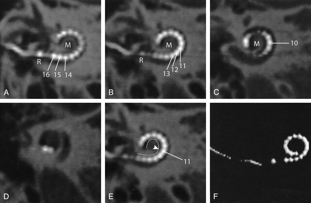
A 25-year-old male patient presented with familial progressive sensorineural hearing loss resulting in postlingual severe deafness (average hearing loss at 1, 2, and 4 kHz, >115 dB). MR imaging and CT scanning of the temporal bone did not show any abnormalities. The patient received a Clarion CII cochlear implant with a Hifocus I electrode with positioner. During the operation, both the electrode array and the positioner could be inserted smoothly. Postoperative MSCT imaging was performed, and MPRs were obtained. The electrode contacts at the basal end of the array are lying in close proximity to the modiolus, confirming the expected medial displacement due to the use of a positioner (Fig 3).
Fig 3.
Case 2. A–D, Oblique multiplanar reformatting of high-resolution MSCT of a HiFocus I electrode array with positioner. The reference electrode (R) is positioned at the level of the cochleostomy. Sixteen individual contacts can be discerned. Contacts 16–12 are positioned in close proximity to the modiolus (M) because of the use of a positioner, which was secondarily inserted along the basal end of the electrode array. On its further course, the electrode array is positioned more laterally within the cochlear lumen. E, Same image as Fig 2B; the modiolar contour is marked (white line). The more lateral position of the distal electrode contacts starting at electrode contact 11 (arrowhead) is shown more clearly. F, 3D VR.
To evaluate the postoperative performance with the implant, speech perception scores were measured in a free-field condition by using the standard CVC (consonant-vowel-consonant) word list (prerecorded female speaker) of the Dutch Society of Audiology at 65 dB SPL and compared with preoperative measurements. The test consists of CVC monosyllabic words, which are presented to the patient in a free-field condition. The score represents the percentage of correctly reproduced phonemes or words (12). The average preoperative phoneme score was 0%. One year after implantation, the average phoneme and word scores were, respectively, 93.5% and 86%.
Case 3
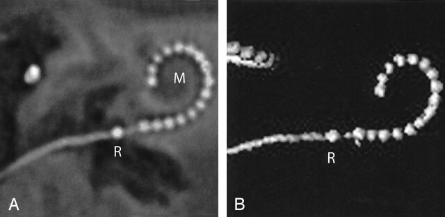
The third case concerns a 65-year-old female patient with progressive sensorineural hearing loss. She had suffered from deafness for 45 years (average hearing loss at 1, 2, and 4 KHz, >120 dB). Preoperative CT and MR imaging showed no abnormalities within the temporal bones or on the auditory pathway. A Clarion CII cochlear implant with a Hifocus I electrode was inserted without the use of a positioner (because changes in design by the manufacturer). As a result, the proximal electrode array could not be placed in a perimodiolar position. After insertion, the electrode array tended to be pushed back, and only a shallow insertion could be achieved. Reformatted postoperative MSCT images clearly show that the electrode array is positioned along the lateral wall of the scala tympani over its entire length (Fig 4).
Fig 4.
Case 3. A, Oblique multiplanar reformatting of high-resolution MSCT of a HiFocus I electrode array without positioner. The reference electrode (R) projects proximal to the cochleostomy. All 16 electrode contacts are positioned within the cochlea. The electrode array courses along the lateral wall of the cochlear lumen over its entire length, leading to a less deep insertion than with the positioner (compare Fig 3). B, On a VR image, a rather shallow insertion of the electrode can be seen. M, modiolus.
Phoneme scores on the CVC word test in quiet (free field, sound only, 65 dB hearing loss) measured preoperatively and 1 year after implantation were, respectively, 0% and 86%, and the word score was 73%.
Discussion
The patients presented in this report received a Clarion CII Bionic ear cochlear implant with a HiFocus I electrode array (in cases 1 and 2 combined with a positioner to achieve a perimodiolar position) (Fig 1). This electrode array is one of the new generation cochlear implants, designed to place the stimulating contacts in close proximity to the spiral ganglion cells located within the modiolus. Preferably, postoperative assessment of this implant should include documentation of the precise location of individual electrode contacts in relation to the modiolus as well as the insertion depth. In this technical note, a MSCT data acquisition protocol that allows detailed evaluation of the final intracochlear position of the electrode array and the individual electrode contacts is described.
To achieve good image quality on postoperative CT images as presented in this article, one has to deal with two problems. The most important one is the image degradation due to artifacts. For accurate visualization of the small electrode contacts and to reduce metallic artifacts, high-resolution scanning and a high-resolution reconstruction filter is required. The other problem is that only part of the electrode array is seen on each section.
The HiFocus I electrode array has 16 contacts, each measuring 0.4 × 0.5 mm with a center-to-center distance of 1.1 mm for neighboring contacts. In addition, there is a reference-contact about 2.5 mm basal to the array of the primary contacts. The contacts and the connecting leads are made of a platinum-iridium alloy (90–10%). To distinguish such small contacts an in-plane and cross-plane resolution of at least 2.5 line pairs per millimeter (lp/mm) is required. For separate visualization of neighboring contacts, a resolution of at least 1.1–1.2 lp/mm is required. The limiting resolution of scanners depends mainly on the scanner design, the reconstruction algorithm (determining mainly the in-plane resolution, measured in the xy plane), the smallest available section thickness and the z axis filtering algorithm (both determining cross-plane resolution, measured along the z axis).
MSCT imaging yields the maximum detail resolution available at present in a clinical setting and provides an (almost) isotropic voxel size when appropriate data acquisition protocols are used. The minimum section thickness of 0.5 mm, and the high-speed multisection cone-beam tomography reconstruction method (MUSCOT) used in our scanner, improve resolution in both the longitudinal and transverse direction. The in-plane visualization of details of 0.4–0.5 mm and cross-plane visualization of details of 0.5–0.7 mm, corresponding with, respectively, 1.0–1.25 lp/mm in plane and 0.7–1.0 lp/mm cross-plane, approaches the requirements for visualization of the individual contacts. Unfortunately, because of blooming, the actual shape of the electrodes cannot yet be visualized accurately (13). Although we do not have experience with cochlear implants of other manufacturers we expect similar results due to similarity in dimensions and alloy. The multisection scanner used at our institution provides an acquisition configuration of 4 × 0.5 mm and uses a high-resolution reconstruction algorithm. Other multisection scanners currently on the market provide a similar acquisition configuration, and further improvements are to be expected in the near future. Therefore, we expect similar results can be yielded with other CT scanners, provided a dedicated imaging protocol is used.
To solve the problem regarding the scan plane, reconstructions can be made to optimize the visualization of the electrode array. The quality of reconstructed images depends crucially upon the resolution of the cross-sectional source data. The (near) isotropic volumetric imaging available with MSCT allows one to reconstruct images in arbitrary planes (Fig 2A, B, 3A–D, 4A, 5B, C) and to make 3D reconstructions of superior image quality (Fig 2C–F, 3F, 4B). Two-dimensional reformations are a useful tool for comprehensive visualization of the electrode array within the complex architecture of the cochlea, because both the electrode contacts and small anatomic structures such as the modiolus and outer cochlear wall can be distinguished.
Fig 5.
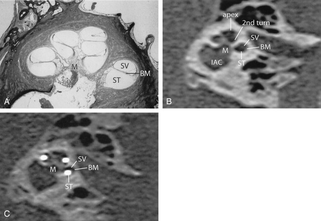
A, Midmodiolar cross-section of human cochlea. The basilar membrane (BM) separates the scala tympani (ST) and scala vestibuli (SV). B, An oblique coronal MPR of a preoperative MSCT at a midmodiolar level is shown. The scala tympani (ST), the scala vestibuli (SV), and the presumed level of the basilar membrane (BM) are indicated in the basal turn of the cochlea. 2nd turn indicates second turn of the cochlea; apex, apical turn of the cochlea, M, modiolus; IAC, internal auditory canal. C, MPR of a postoperative high-resolution MSCT image parallel to the modiolus and perpendicular to the basal turn of the cochlea. Although the basilar membrane (BM) itself cannot be visualized, the position of the electrode contacts does correspond with full insertion of the array in the scala tympani (ST).
Oblique axial reformations, parallel to the basal turn of the cochlea and perpendicular to the modiolus, correspond to the plane of the electrode array. They provide a comprehensible image of the precise intracochlear position of the electrode array and its relation to the modiolus (Figs 2–4). Accurate evaluation of the exact position of the electrode array might lead to a better understanding of the wide variability in fitting parameters (e.g., T levels) and for speech perception in cochlear implant recipients. This will have implications in the development and selection of speech-processing programs and improvement of insertion techniques and electrode design.
Insertion of a cochlear implant bears the risk of rupturing fine intracochlear structures, which might lead to further neuronal losses and osteoneogenesis (14). Until now, assessment of insertion trauma has only been done by means of histologic studies (4, 14, 15) or in vitro temporal bone imaging (4, 6, 7, 14). On the basis of the findings in this study, MSCT might become a useful tool for in vivo examination of such peroperative intracochlear trauma. Oblique coronal images, reconstructed perpendicular to the basal turn of the cochlea and parallel to the modiolus, can be used for this assessment. Although the osseous spiral lamina and basilar membrane cannot be discerned on these images, the position of the electrode contacts indicates whether the array is situated in the scala tympani or in the scala vestibuli (Fig 5). Although subtle traumatic lesions cannot be shown, this is a clear advantage over conventional radiographs and the obtained images are at least comparable to previously reported in vitro imaging with cone beam CT (7).
More gross effects on the inserted array can be evaluated on 3D reformations by using a VR technique. The images are comparable to conventional radiographs but yield the possibility to view the electrode array under arbitrary angles. As shown in case 1, where two contacts were left out of the map (Fig 2), imaging findings will influence programming.
Conclusion
The data acquisition protocol presented in this report enables visualization of both the individual contacts and anatomic details of the cochlea within the plane of the electrode array, thus providing useful information to optimize the function of the cochlear implant in individual patients. Until now, CT scanning in cochlear implant recipients was reserved for patients with suspected complications. The technological advances of MSCT might, however, lead to expansion of the clinical applications, provided that dedicated acquisition parameters are used.
Footnotes
We wish to thank Dr. F. Linthicum from the House Ear Institute for kindly providing the histologic cross-section.
References
- 1.NIH Consensus Statement. Cochlear implants in adults and children. NIH Consensus Development Conference . May 15–17,1995;13:1–30 [PubMed] [Google Scholar]
- 2.Frijns JHM, Briaire JJ, De Laat JAPM, Grote JJ. Initial evaluation of the Clarion CII cochlear implant: speech perception and neural response imaging. Ear Hear 2002;23:184–197 [DOI] [PubMed] [Google Scholar]
- 3.Xu J, Xu SA, Cohen LT, Clark GM. Cochlear view: postoperative radiography for cochlear implantation. Am J Otol 2000;21:49–56 [PubMed] [Google Scholar]
- 4.Roland JT, Fishman AJ, Alexiades G, Cohen NL. Electrode to modiolus proximity: a fluoroscopic and histologic analysis. A J Otol 2000;21:218–225 [DOI] [PubMed] [Google Scholar]
- 5.Balkany TJ, Eshraghi AA, Yang N. Modiolar proximity of three perimodiolar cochlear implant electrodes. Acta Otolaryngol 2002;122:363–369 [DOI] [PubMed] [Google Scholar]
- 6.Xu J, Stevenson AW, Gao DC, et al. The role of radiographic phase-contrast imaging in the development of intracochlear electrode arrays. Otol Neurotol 2001;22:862–868 [DOI] [PubMed] [Google Scholar]
- 7.Husstedt HW, Aschendorff A, Richter B, et al. Nondestructive three-dimensional analysis of electrode to modiolus proximity. Otol Neurotol 2002;23:49–52 [DOI] [PubMed] [Google Scholar]
- 8.Whiting BR, Bae KT, Skinner MW. Cochlear implants: three-dimensional localization by means of coregistration of CT and conventional radiographs. Radiology 2001;221:543–549 [DOI] [PubMed] [Google Scholar]
- 9.Yang SY, Wang G, Skinner MW, et al. Localization of cochlear implant: electrodes in radiographs. Med Phys 2000;27:775–777 [DOI] [PubMed] [Google Scholar]
- 10.Ketten DR, Vannier MW, Skinner MW, et al. In vivo measures of cochlear length and insertion depth of nucleus cochlear implant electrode arrays. Ann Otol Rhinol Laryngol 1998;107:1–16 [PubMed] [Google Scholar]
- 11.International Commission on Radiological Protection. Recommendations of the International Commission on Radiological Protection. ICRP publication 60. Oxford: Pergamon Press;1990
- 12.Bosman AJ, Smoorenburg GF. Intelligibility of Dutch CVC syllables and sentences for listeners with normal hearing and with three types of hearing impairment. Audiology 1995;34:260–284 [DOI] [PubMed] [Google Scholar]
- 13.Hsieh J. Computed tomography: principles, design, artifacts, and recent advances. Bellingham: SPIE—the International Society for Optical Engineering;2003. :1–388
- 14.Richter B, Jaekel K, Aschendorff A, et al. Cochlear structures after implantation of a perimodiolar electrode array. Laryngoscope 2001;111:837–843 [DOI] [PubMed] [Google Scholar]
- 15.Tykocinski M, Cohen LT, Pyman BC, et al. Comparison of electrode position in the human cochlea using various perimodiolar electrode arrays. Am J Otol 2000;21:205–211 [DOI] [PubMed] [Google Scholar]


