Abstract
Summary: We report the successful stent placement and secondary coil placement in a wide-necked persistent trigeminal artery (TA) aneurysm, in which the internal carotid artery (ICA) was preserved and the TA “jailed.” Nine-month follow-up angiography revealed a completely obliterated aneurysm and patent parent ICA and TA. MR images obtained at 16-mo follow-up showed no infarction of the brain in the distribution of the jailed TA. The risks of stent jailing and possible solutions are discussed.
Recently, investigators have reported combining porous metallic stents with coil technology to treat complex wide-necked aneurysms that otherwise would not be accessible for standard endovascular treatment (1). Although current stent technology is successful in sidewall aneurysms, bifurcation aneurysms remain a challenge because of the risks involving the patency of side branches. We report our experience with an aneurysm located at the origin of the persistent trigeminal artery (TA) that we successfully occluded by using stent-assisted coil placement, preserving the internal carotid artery (ICA) and “jailing” the TA.
Case Report
Clinical Presentation
A 58-year-old woman with a sudden onset of headaches and vomiting was admitted to an outside hospital. Emergency CT findings confirmed a subarachnoid hemorrhage. According to the report, the angiogram obtained at that institution showed a posterior communicating artery aneurysm (PComA). During angiography, a left-sided hemiparesis developed as a result of a thromboembolic lower-division occlusion of the right middle cerebral artery (MCA).
Twelve days after the initial ictus and partial recovery from neurologic symptoms, the patient was taken to the operating room for surgical clipping of the aneurysm. Surgery was terminated when the aneurysm could not be found and a cavernous carotid artery aneurysm was suspected. The patient was transferred to our institution for further treatment.
When admitted, the patient was alert and oriented and had a left-sided hemiparesis. Her angiogram showed an aneurysm of the persistent TA on the right side. The basilar artery was supplied from both the large persistent TA and the right PComA. The basilar trunk was well supplied through both vertebral arteries. An endovascular approach was chosen because of the difficulty of exploring and clipping the aneurysm at surgery.
Endovascular Intervention
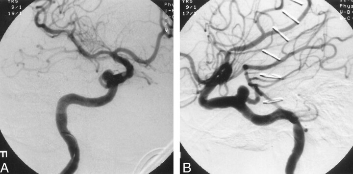
The right ICA angiogram obtained at our institution showed a persistent TA aneurysm measuring 4.5 × 5 × 5 mm, with a wide neck measuring 4.5 mm (Fig 1). The previously occluded lower division of the right MCA had completely recanalized, and no other vessel abnormalities were found. The diagnostic catheter was then exchanged for a 6F guiding catheter (Envoy; Cordis Endovascular Systems/Johnson & Johnson, Miami, FL) and placed in the distal cervical ICA. A two-tip marked microcatheter (Prowler 14; Cordis Endovascular Systems) was navigated with a 0.014-in microguidewire (Transend; Boston Scientific, Natick, MA) through the guide catheter into the aneurysm sac. Coil placement was attempted by using a three-dimensional (3D) Guglielmi detachable coil (GDC) (GDC-10; helix size, 5 mm; length, 10 cm); it failed because the coil mass kept herniating into the parent artery or occluding the origin of the TA.
Fig 1.
Right ICA angiograms obtained after failed surgical clipping of the aneurysm. Views of the wide-necked persistent TA aneurysm show the relationship of the parent vessel to the aneurysm.
A, Oblique.
B, Lateral.
We decided to place a stent in the ICA and perform a secondary coil procedure in the aneurysm. The patient received intravenous anticoagulation with a 5000-U heparin bolus. The activated clotting time was maintained at approximately 250 s. The microcatheter was removed. A 4 × 12-mm coronary stent (Medtronic AVE GFX II; Santa Rosa, CA) was advanced over a 0.014-in guidewire (Wizard, Cordis Endovascular Systems) (Fig 2A). The stent was deployed in the cavernous ICA segment, bridging the aneurysm neck (Fig 2B).
Fig 2.
Angiograms illustrate stent-assisted coil placement in a persistent TA aneurysm.
A, Lateral view shows the stent bridging the aneurysm prior to deployment (arrows). The guidewire for the stent delivery system has been introduced into the angular artery. The stiff guidewire causes visible kinking of the ICA.
B, The stent is fully deployed (solid arrows), and the first detached coil, placed through the stent struts, is visible. The lower part of the coil helix covers the origin of the persistent TA (open arrow).
C, After additional coils are inserted, the first coil is pushed back into the aneurysm dome, opening the origin of the persistent TA (open arrow). The stent supports the coil mass. The small end of the coil is trapped between the vessel wall and the aneurysm (solid arrow).
The procedure was performed with a biplane fluoroscopic and roadmapping technique. Use of zoom fluoroscopy ensured that the stent was properly placed, especially at the skull base. The proximal and distal radiopaque markers on the balloon were used as reference points. Optimal placement required that at least 2 mm of the stent at the proximal and distal ends be embedded in the healthy arterial segment. The balloon was inflated for 30 s at 8 atm. After full expansion of the stent was verified, the balloon was deflated and withdrawn. The flow pattern in the aneurysm-parent artery complex showed some changes but no substantial flow stasis was visible. The flow in the TA was normal. A microcatheter (Prowler 14) was easily navigated over a microguidewire (Transend 0.014 in) through the stent struts and into the aneurysm sac (Fig 2C). We removed the wire and packed the aneurysm with seven GDC-10 coils, preserving the ICA and jailing the TA. The lower part of the initial 3D coil helix covered the origin of the persistent TA. After additional regular coils were inserted, the first coil was pushed back into the aneurysm dome; this opened the origin of the persistent TA. The stent easily supported the coil mass. A small section of the last coil herniated, but it was trapped between the ICA wall and the stent. The microcatheter was easily removed. The postprocedural angiogram showed an excellently placed stent and a completely obliterated aneurysm with normal flow in the TA. No peri- or postprocedural neurologic deficit occurred. MR imaging of the brain was not performed at that time.
The patient was under conscious sedation and analgesia (Versed, Dilaudid, fentanyl) for periprocedural neurologic monitoring. She was then transferred to a neurologic intensive care unit, where she received intravenous heparin for 24 h and Plavix 75 mg and aspirin 375 mg by mouth every day. Two days after the endovascular procedure, she was moved to a regular unit, where she began intense physical and speech therapies. When discharged, the patient had substantially regained her left-sided motor functions.
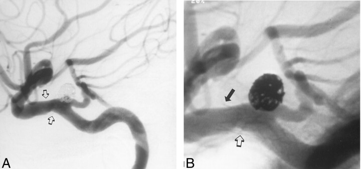
A 9-mo follow-up angiogram showed a completely obliterated aneurysm and patency both of the TA and the carotid artery (Fig 3). Intimal hyperplasia caused minor narrowing of the ICA at the stented segment. These changes were seen at the distal end of the stent as well as at the inner curve of the stented segment. At that time, the patient had no new neurologic symptoms, and her left arm and shoulder weakness had improved.
Fig 3.
Lateral 9-mo follow-up angiograms.
A, Image shows complete aneurysm obliteration, a patent persistent TA, and mild narrowing of the ICA at the stented segment (arrows).
B, The distal narrowing is around the distal end of the stent (solid arrow). Further intimal hyperplasia is seen on the inner curve of the arterial wall, which already shows some minor changes prior to stent placement (open arrow) (see also Fig 1).
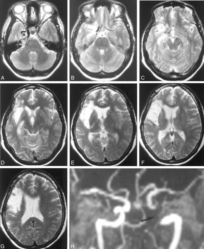
MR imaging obtained 16 mo after the procedure did not show any evidence of thromboembolic events in the distribution of the TA (Fig 4A–G). However, they revealed the right insular infarction associated with the initial angiogram. MR imaging and MR angiographic findings were inconclusive because of a signal void within the stented arterial segment (Fig 4A and H).
Fig 4.

T2-weighted (2800/90, TR/TE) MR images and MR angiograms obtained 16 mo after stent implantation.
A, MR image shows a signal void in the area of the right ICA with the stent (open arrow). Note that the stent covers the origin of the primitive TA (solid arrow).
B–G, MR images do not show any infarction from thromboembolic events. Note the old insular infarction associated with the initial diagnostic angiography.
H, 3D TOF MR angiogram depicts a signal void within the stented lumen of the right ICA and persistent TA (arrow).
Discussion
Until recently, the transfer of coronary stent technology to the intracranial vascular system has been limited by the lack of available stents and delivery systems capable of safe and effective navigation to the neurovascular system. Stent placement was limited to the extracranial circulation because the stents were too stiff or large, but with the introduction of a new generation of highly flexible delivery systems and appropriate microguidewires with low-profile stents, as well as recent advances in angiographic imaging equipment, the stent-based endovascular treatment of intracranial vascular diseases has become reality. However, while stent placement in an artery with sidewall aneurysms is technically easy, bifurcation lesions remain a challenge. To overcome this problem, current efforts are focusing on the development of bifurcation stents. Concepts related to the inverted Y-shaped aortoiliac graft serve as a platform, but, so far, no device has been approved for clinical application.
In our patient, the aneurysm was located at the origin of the persistent TA. A previous attempt at surgical clipping had failed. We tried conventional endovascular coil insertion by using a 3D GDC system, but we were unsuccessful because of the wide neck of the aneurysm. We proceeded with stent-assisted coil placement, which required jailing of the TA. The 9-mo follow-up angiogram showed a patent TA, no stenosis of the stented ICA, and a completely occluded aneurysm. No ischemic event occurred during the 17-mo clinical follow-up. MR images obtained 16 mo after stent placement showed no infarctions in the distribution of the TA. On the basis of our in vitro findings with neurostents, in which no substantial deflection or rotation in a 1.5-T magnet was detected, no adverse events (eg, stent displacement or shearing of clots) should be expected, even if MR imaging is performed immediately after stent implantation.
Jailing of side branches during stent placement in atherosclerotic occlusive disease is a well-described procedure in coronary intervention, and it has a favorable outcome (2). However, as many as 6–13% of side branches may become occluded or stenotic because of plaque shifting during stent placement in the parent vessel (3); this process is known as the snowplow effect. Several technical modifications have been suggested to overcome this problem. The simplest approach seems to be stent implantation in the parent vessel and subsequent angioplasty in the side branch through the stent interstices or by using the kissing balloon technique (4). A more complex technique uses one stent at the ostium of the side branch followed by one or two stents in the parent vessel (T, inverted V, or Y technique). This method provides a complete reconstruction of the bifurcation and reduces the 10% risk of side-branch dissection associated with angioplasty alone (3). Although the short-term results are promising (as reported from one study of the complex technique), rates of major cardiac events were higher at 18-mo follow-up (3–5).
In selected cases, to keep side branches patent and coils in place, bifurcation stent implantation with reconstructive coronary techniques may be helpful, until appropriate devices are available. The snowplow effect is not seen when stents are used for the treatment of aneurysms. However, the risk of occluding larger branches and important brain perforating-arteries covered by the stent might be increased. In a recently published report, stent placement in the aneurysms required jailing of the ophthalmic artery in two patients and jailing of the anterior inferior cerebellar artery (AICA) in two other cases. No clinical or angiographic evidence of thrombosis was observed in any of these vessels, probably because of the high porosity of the stents used (1). Later, the same group reported a total of 19 successfully deployed intracranial stents (Medtronic AVE GFX II and INX) in cases of atherosclerotic disease and aneurysms at various locations (6). Eleven angiographically visible branches were jailed, including the posterior inferior cerebellar artery, AICA, ophthalmic artery, and lenticulostriate artery. Follow-up angiograms obtained at mean of 19 wk after stent deployment showed patent side branches without any origin stenosis. Clinically, no ischemic events occurred in the vascular distribution. However, no MR images of the distribution of the jailed arteries were obtained. Similar findings were observed in experimental studies of nondiseased arteries. Stents were placed in a canine model across muscular branches arising from the vertebral artery (approximately 0.5 mm in diameter) or in a rabbit model to jail lumbar arteries (average, 0.65 mm) arising from the aorta (7, 8). Follow-up images obtained at 3 mo did not show any occlusion of the jailed arteries or origin stenosis.
MR imaging or MR angiography are desirable noninvasive tools for the follow-up of neurostents. However, because currently used stents are made of metallic alloys, signal void might be of concern, as they were in our case. The surrounding tissues are adequately visualized, but the stent lumen is not seen. This limitation leads to an inaccurate appraisal of the function of the stent. Although MR stent artifacts present a barrier for adequate neurostent follow-up, many stent and MR parameters that can be improved have been identified; the result with improvements is superior imaging of the vascular space. These parameters are variables involving both stent design and MR sequences.
Impurities of stent alloys and its ferromagnetic properties contribute to the homogeneity of the magnetic field (9–11). Most commercially available stents are made of nitinol, stainless steel, cobalt, or tantalum; these are nonferromagnetic materials, and they do not disturb the homogeneity of the static magnetic field. However, study findings have shown that varying degrees of susceptibility artifact are based on the relative impurities of each particular alloy (10, 12). The inability to visualize the stent lumen is correlated to the inherent RF permeability (stent shielding effect). In addition, RF pulse induces eddy currents around the stent struts that lead to local magnetic field inhomogeneity. The stent, acting as a Faraday cage, attenuates the signal from the stent lumen on its way to the receiver coils. Most recent stent designs have improved the visualization of the stent lumen (Wakhloo and Sandhu, unpublished data, 2001). In addition, different MR imaging sequences can be used to reduce the signal void. Study findings have shown that T1-weighted spin-echo pulse sequences produce artifacts smaller than those of fast spoiled gradient-recalled echo pulse sequences. Shorter TEs also decrease stent artifacts, and contrast-enhanced MR angiography may help to better delineate the stent lumen (11).
Conclusion
Stent-assisted coil insertion can be used to manage wide-necked intracranial aneurysms at vessel branching points. The stent prevents the coil from migrating into the parent vessel or side branches. For complex bifurcation lesions, various reconstructive techniques are available, as described in the coronary literature. Signal void artifacts that prevent sufficient evaluation of the lumen of current metallic neurostents limit the diagnostic value of MR imaging and MR angiography. However, with the advent of new technologies that optimize stent geometry, alloy properties, and imaging technology, the use of MR techniques for patient follow-up will be feasible.
Addendum
A recent 2-year follow-up angiogram showed no changes to the previous 9-mo follow-up angiogram.
Acknowledgments
We wish to thank Dagmar Schnau for her editorial assistance.
References
- 1.Lanzino G, Wakhloo AK, Fessler RD, Hartney ML, Guterman LR, Hopkins LN. Efficacy and current limitations of intravascular stents for intracranial internal carotid, vertebral, and basilar artery aneurysms. J Neurosurg 1999;91:539–547 [DOI] [PubMed] [Google Scholar]
- 2.Fischman DL, Savage MP, Leon MB, et al. Fate of lesion-related side branches after coronary artery stenting. J Am Coll Cardiol 1993;22:1641–1646 [DOI] [PubMed] [Google Scholar]
- 3.Caputo RP, Chafizadeh ER, Stoler RC, et al. Stent jail: a minimum security prison. Am J Cardiol 1996;77:1226–1230 [DOI] [PubMed] [Google Scholar]
- 4.Pan M, de Lezo JS, Medina A, et al. Simplex and complex stent strategies for bifurcated coronary arterial stenosis involving the side branch origin. J Am Cardiol 1999;83:1320–1325 [DOI] [PubMed] [Google Scholar]
- 5.Chevalier B, Glatt B, Royer T, Guyon P. Placement of coronary stents in bifurcation lesions by the “culotte” technique. Am J Cardiol 1998;82:943–949 [DOI] [PubMed] [Google Scholar]
- 6.Lopes DK, Ringer AJ, Boulos A, Guterman LR, Hopkins LN. Patency of arterial branches crossed by intracranial stents: fate of the “jailed” artery. Paper presented at: 1st American-Japanese Meeting for Surgical and Endovascular Treatment of Cerebrovascular Disorders, AANS/CNS and ASITN; February 9–12, 2001; Hawaii, HI
- 7.Wakhloo AK, Tio FO, Lieber BB, Schellhammer F, Graf M, Hopkins LN. Self-expanding nitinol stents in canine vertebral artery: hemodynamics and tissue response. AJNR Am J Neuroradiol 1995;16:1043–1051 [PMC free article] [PubMed] [Google Scholar]
- 8.Masuo O, Terada T, Tsuura M, et al. Can the perforating arteries remain patent after intracranial arterial stenting: initial experiment using experimental model. 39th Annual Meeting, American Society of Neuroradiology; April 23–27, 2001; Boston, MA
- 9.Klemm T, Duda S, Machann J, et al. MR Imaging in the presence of vascular stents: a systematic assessment of artifacts for various stent orientations, sequence types, and field strengths. J Magn Reson Imaging 2000;12:606–615 [DOI] [PubMed] [Google Scholar]
- 10.Hilfiker PR, Quick HH, Debatin JF. Plain and covered stent-grafts: in vitro evaluation of characteristics at three-dimensional MR angiography. Radiology 1999;211:693–697 [DOI] [PubMed] [Google Scholar]
- 11.Shellock FG, Shellock VJ. Metallic stents: evaluation of MR imaging safety. AJR Am J Roentgenol 1999;173:43–547 [DOI] [PubMed] [Google Scholar]
- 12.Lenhart M, Voelk M, Manke C, et al. Stent appearance at contrast-enhanced MR angiography: in vitro examination with 14 stents. Radiology 2000;217:173–178 [DOI] [PubMed] [Google Scholar]


