

Abstract
BACKGROUND AND PURPOSE: Aneurysm embolization is not without risk: numerous technical aspects are considered before, during, and after the procedure. The purpose of this study was to show the position of the detachment zone of a Guglielmi detachable coil (GDC) with respect to the catheter tip for various microcatheters and marker alignments.
METHODS: Six types of commonly used microcatheters were tested (Excel-14, Excelsior, FasTracker-10, Prowler-10, Prowler-14, and Rebar-14). First, the catheter markers and the distance from the catheter tip to the distal end of the proximal and distal markers of each catheter were compared. Second, the coil maker was aligned with the catheter marker. Third, the distal 3 cm of the microcatheter was modified by random shaping, with or without steaming. Last, marker alignment was tested with resterilized microcatheters (ethylene oxide gas sterilization).
RESULTS: The length of the catheter marker and the distance between the catheter tip and the distal end of the proximal and distal catheter markers varied among the microcatheters. Sometimes, they varied even within the same microcatheter type. When a GDC was advanced until the proximal end of the marker on the delivery wire was exactly distal to the proximal catheter marker, the coil detachment zone was positioned at approximately 1.0 to 1.5 mm outside the catheter tip. Steaming or shaping of the distal 3 cm of the microcatheters resulted in the GDCs protruding more from the catheter tip. Resterilization also had an effect of marker distance shortening. Microcatheters were easily stretched by usual handling, such as removing a shaping mandrel from the catheter tip.
CONCLUSION: Our study shows that proper marker alignment is influenced by many factors, including microcatheter type, steaming, shaping, sterilization, and manual handling.
Aneurysm embolization with Guglielmi detachable coils (GDCs) (Boston Scientific, Natick, MA) is not without risk. It is performed with special care by interventionists. Numerous technical aspects are considered and reconsidered before, during, and after the procedure. Even minor techniques are readjusted and modified in each case for safe and effective coil packing. Proper marker alignment is one of the important technical considerations. For safe and effective aneurysm embolization, neurointerventionists should be able to advance or retrieve GDCs according to their intention and with the appropriate degree of anticipation. Such precision will be possible only when they know exactly what is moved and by how much with their handling.
The manufacturer recommends that a GDC should be advanced until the proximal end of the radiopaque marker on the delivery wire is exactly distal to the proximal marker on a two-tip microcatheter of a 3-cm marker distance (“Capital T alignment”). Regardless of manufacturers, almost all the available two-tip microcatheters for detachable platinum coils have a 3-cm marker distance. With increasing experience, we have come to the conclusion that marker distance may differ among various microcatheters and that it may also be affected by various catheter manipulations. For practical requirements, we performed this study to determine where the coil detachment zone is positioned with respect to the catheter tip at various marker alignments, whether it changes according to individual microcatheter type, and how it is altered by usual modifications or manipulations.
Methods
Six types of commonly used two-tip microcatheters were tested: Excel-14 (Boston Scientific), Excelsior (Boston Scientific), FasTracker-10 (Boston Scientific), Prowler-10 (Cordis Endovascular Systems, Miami Lakes, FL), Prowler-14 (Cordis Endovascular Systems), and Rebar-14 (Micro Therapeutics, Inc., Irvine, CA). Five of each type of microcatheter were used for comparisons. We did not measure or compare the distance between two catheter markers, because the distance between the catheter tip and the distal end of the proximal catheter marker has a more practical meaning. We herein call that measurement the marker distance. Each catheter was photographed together with a 0.01-mm scaled micrometer (Olympus, Tokyo, Japan), and all measurements were obtained three times by a single investigator (O.K.K) using the magnified photographic images.
Various types and sizes of GDCs (total, 16) were used for the marker alignment test: non-SyngerG GDC (GDC-18) (2), GDC-10 (5), SynerG GDC (GDC-10) (3), GDC-10 3D (1), GDC-10 Soft (2), GDC-10 Soft Stretch-Resistant (2), and GDC-10 Ultrasoft Stretch-Resistant (1). After flushing the microcatheter and attaching a rotating hemostatic valve, a coil was introduced and advanced into the microcatheter. First, the proximal end of the coil marker was positioned exactly distal to the distal end of the proximal catheter marker. We described this alignment as usual alignment. Second, without regard for marker alignment, the coil was advanced until the coil detachment zone extended approximately 0.2 to 0.3 mm from the microcatheter tip. This was considered to be the ideal alignment because the coil detachment zone was positioned just outside the catheter tip. For each alignment, fluoroscopic images and photographs were obtained. A 1-cm stainless steel ball was used as a reference for the radiologic images.
Changes in position of the coil detachment zone with respect to the catheter tip were tested with two commonly practiced manipulations: steaming and catheter curving. Steam was applied for 20 seconds. Tortuous vessels were simulated by the random construction of catheter curves. First, to achieve proximal tortuosity, several curves were made on a 5F conventional angiographic catheter and a microcatheter was inserted through it. Second, to achieve distal tortuosity, curves were made on the distal 3 cm of the microcatheters with shaping mandrels. The distal catheter curves were made either with or without steaming. Additionally, changes of the marker distance were tested in resterilized microcatheters (ethylene oxide gas sterilization).
Results
Detachment Zone of GDC
The detachment zone of the SynerG GDC has a peculiar structure that differs from that of the non-SyngerG GDC. It has a polymer coverage that blocks electric current to the coil part. This is apparent as a small transparent zone in fluoroscopy (Fig 1A). The distance from the proximal end of the coil maker to the detachment zone of the SynerG GDC was the same or approximately 0.2 to 0.3 mm shorter than that of the non-SyngerG GDC (Fig 1A and B). We used a non-SyngerG GDC or a SyngerG GDC with the same marker distance to that of the non-SyngerG GDC for the marker alignment test. The length of the marker on the delivery wire could be different, but even with these coils, the distance from the proximal end of the coil maker to the detachment zone was similar to that of the other GDCs (Fig 1C).
Fig 1.

Fluoroscopic images show distance from proximal end of coil maker to detachment zone of GDC. The diameter of the black circle is 1 cm.
A, Distance from proximal end of coil maker to detachment zone of SynerG GDC is approximately 0.2 to 0.3 mm shorter than that of non-SyngerG GDCs. Note the small transparent zone near the real detachment zone (arrow) of the SynerG GDC.
B, Fluoroscopic image shows same distance from proximal end of coil maker to detachment zone in both SynerG and non-SynerG GDCs. The microcatheter is an Excelsior. Note the marker alignment and the position of the coil detachment zone from the catheter tip.
C, GDC has shorter marker (arrow). Despite the shorter length, the distance from the proximal end of the coil maker to the detachment zone is similar to that of another GDC.
Catheter Markers, Marker Distance, and Radiographically Transparent Zone of Catheter Tip
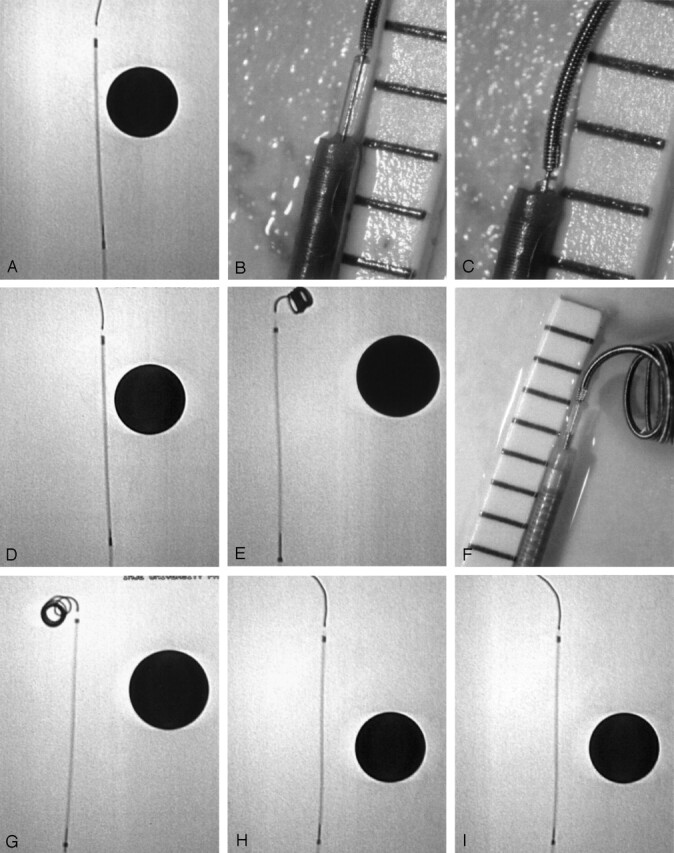
The proximal catheter markers were similar in length, whereas the Prowler had a longer marker (approximately 2–2.5 times as long as those of other catheters). The length of the distal marker of the Rebar-14 was approximately 1.5 times as long as that of the Excel-14 (Fig 2A). The length of the radiographically transparent zone that extended from the distal catheter marker was similar for the Excel, Excelsior, and Rebar catheters, whereas the Prowlercatheters had the shortest transparent zone (Table, Fig 2A). One of Excel catheters tested showed a longer transparent zone than those of the other Excel catheters (Fig 2B). The distance between the catheter tip and the distal end of the proximal catheter marker was similar in the Excel, Excelsior, Prowler, and FasTracker GDCs, whereas it was approximately 0.5 mm longer in the Rebar GDC (Fig 2C and D). In one Excelsior catheter, it was approximately 0.5 mm shorter than in other Excelsior catheters (Fig 2E).
Fig 2.

Photographs and fluoroscopic images show proximal and distal catheter markers, catheter part extended from distal catheter marker (real end of microcatheter), and distance between catheter markers. The diameter of the black circle in the fluoroscopic image is 1 cm. A division of the ruler shown in the photographs (A and C) is 1 mm.
A, Photograph shows proximal catheter markers. From left: Excel-14, Rebar-14, Excelsior, Prowler-14, and FasTracker-10.
B, Photograph shows that one Excel catheter (left) has longer catheter part beyond distal catheter marker than that of Excelsior (right). It measured 1.68 mm.
C, Photograph shows proximal catheter markers. The distal ends of the microcatheters are arranged in the same position as shown in A. Arrow indicates the distal parts of the catheters.
D, Fluoroscopic image shows relative locations of proximal catheter markers when distal ends of microcatheters are arranged in similar positions. From left: Excel-14, Rebar-14, Excelsior, Prowler-14, and FasTracker-10.
E, Fluoroscopic image shows that one Excelsior has shorter marker distance than another Excelsior. From left: Excelsior, Excelsior, and Excel-14.
Length profiles of the microcatheters tested
| Excel-14* | Rebar-14 | Prowler-14 | Excelsior | FasTracker-10 | Prowler-10 | |
|---|---|---|---|---|---|---|
| Proximal marker | 0.59 ± 0.01 | 0.66 ± 0.05 | 1.28 ± 0.04 | 0.60 ± 0.03 | 0.62 ± 0.04 | 1.27 ± 0.03 |
| (0.57 ∼ 0.60) | (0.58 ∼ 0.70) | (1.25 ∼ 1.36) | (0.57 ∼ 0.63) | (0.58 ∼ 0.65) | (1.25 ∼ 1.36) | |
| Distal marker | 0.61 ± 0.01 | 0.93 ± 0.02 | 1.41 ± 0.05 | 0.59 ± 0.03 | 0.61 ± 0.02 | 1.44 ± 0.07 |
| (0.59 ∼ 0.62) | (0.90 ∼ 0.95) | (1.33 ∼ 1.47) | (0.56 ∼ 0.63) | (0.60 ∼ 0.62) | (1.34 ∼ 1.52) | |
| Radiographically transparent zone of the catheter tip | 0.80 ± 0.05 | 0.82 ± 0.10 | 0.50 ± 0.09 | 0.74 ± 0.04 | 0.79 ± 0.12 | 0.44 ± 0.04 |
| (0.75 ∼ 0.88) | (0.73 ∼ 0.93) | (0.43 ∼ 0.65) | (0.68 ∼ 0.77) | (0.65 ∼ 0.88) | (0.40 ∼ 0.50) | |
| Position of the coil detachment | 1.50 ± 0.23 | 1.18 ± 0.21 | 1.43 ± 0.15 | 1.56 ± 0.27 | 1.33 ± 0.15 | 1.42 ± 0.17 |
| zone from the catheter end with usual alignment | (1.22 ∼ 1.73) | (0.08 ∼ 1.29) | (1.24 ∼ 1.57) | (1.22 ∼ 1.80) | (1.21 ∼ 1.50) | (1.18 ∼ 1.57) |
Note.—Average (mm) ± SD (minimum ∼ maximum); usual alignment refers to the marker alignment with which non-SyngerG GDC is advanced until the proximal end of the radiopaque marker on the delivery wire is exactly distal to the proximal marker on a microcatheter.
An Excel-14 microcatheter with a long transparent zone of the catheter tip (1.68 mm) is excluded.
Marker Alignment Test
When a GDC marker was aligned according to the manufacturer’s recommendation (usual alignment) (ie, the GDC was advanced until the proximal end of the radiopaque marker on the delivery wire was exactly distal to the proximal marker on the microcatheter), the coil detachment zone was positioned at approximately 1.5 mm outside the catheter tip for the Excel, Excelsior, FasTracker, and Prowler and at approximately 1 mm for the Rebar (Table, Fig 3A–N). In one of the Excelsior catheters tested, which had a 0.5-mm-shorter marker distance, it was positioned at approximately 2 mm from the tip (Fig 3M). When the GDC was slightly retrieved and positioned to the ideal alignment, the radiologic marker alignment differed from the usual alignment as a matter of course (Fig 3A–N). Steaming shortened the marker distance, but the degree of shortening according to steaming time was not investigated. The degree of catheter shortening appeared to be the same for all braided catheters.
Fig 3.

Photographs and fluoroscopic images show position of coil detachment zone with usual marker alignment and marker alignment at ideal alignment. The diameter of the black circle in the fluoroscopic images is 1 cm. A division of the ruler shown in the photographs (B, C, and F) is 1 mm.
A, Fluoroscopic image shows usual alignment in Prowler-14.
B, Photograph shows position of coil detachment zone in this alignment.
C, GDC is retrieved to ideal alignment.
D, Proximal end of coil marker is aligned with proximal end of proximal catheter marker.
E, Marker alignment and position of coil detachment zone in Excel-14 (fluoroscopic image).
F, Marker alignment and position of coil detachment zone in Excel-14 (photograph).
G, Ideal alignment in Excel-14.
H, Marker alignment and position of coil detachment zone in Rebar-14.
I, Ideal alignment in Rebar-14.
J, Marker alignment and position of coil detachment zone in Excelsior.
K, Marker alignment and position of coil detachment zone in Excelsior. An Excelsior that has a 0.5-mm-shorter marker distance than the other Excelsior catheters (see Fig 2E) is used.
L, Ideal alignment in Excelsior.
M, Marker alignment and position of coil detachment zone in FasTracker-10.
N, Ideal alignment in FasTracker-10.
Catheter Modifications and Manipulations
Proximal catheter curves did not influence marker alignment. However, the catheter curves on the distal 3 cm had an effect of marker distance shortening, causing the coil detachment zone to protrude further from the catheter tip (Fig 4A–C). Catheter curving with steaming (steam shaping) made the coil protrude more from the catheter tip (Fig 4D–F). Ethylene oxide gas sterilization also had an effect of marker distance shortening (Fig 4G). The degree of catheter shortening appeared to be similar for all catheter types. All catheters tested were easily stretched by gentle manual stretching, vigorous rubbing with saline-soaked gauze, or rough removal of shaping mandrels. With these manipulations, the marker distance could be elongated by ≥2 to 3 mm (Fig 4H).
Fig 4.
Fluoroscopic images and photograph show changes in position of coil detachment zone from catheter tip with catheter manipulations. The diameter of the black circle in the fluoroscopic images is 1 cm. A division of the ruler shown in the photograph (E) is 1 mm.
A, Fluoroscopic image shows that random catheter curve (Prowler-10) on distal 3 cm causes coil detachment zone to protrude further from catheter tip.
B, Fluoroscopic image shows marker alignment at ideal alignment in same catheter as that shown in A.
C, Schematic illustrations show effect of marker distance shortening with catheter curves. The stiff delivery wire maintains a relatively straight course within a tortuous microcatheter (right). The coil is thus more protruded than with a straight catheter (left). Catheter curves without steaming simulate vascular tortuosity.
D, Fluoroscopic image shows that steam shaping of an Excel-14 makes coil protrude more from catheter tip than with unmodified Excel-14.
E, Photograph shows that steam shaping of Excel-14 makes coil protrude more from catheter tip than with unmodified Excel-14.
F, Fluoroscopic image shows marker position at ideal alignment in same catheter.
G, Fluoroscopic image shows shortening of marker distance after ethylene oxide gas sterilization. The catheter is an Excel-14.
H, Fluoroscopic image shows various lengthening of catheters after gentle manual stretching. All catheters are Excel-14s.
Discussion
Basically, safe and precise positioning of a GDC within an aneurysm is accomplished with the aid of direct fluoroscopic visualization of a radiopaque platinum coil part and precise marker alignment. However, fluoroscopic visualization is rarely possible because the previously deployed coil part interferes with direct visualization of the detachment zone. Therefore, marker alignment is practically important for precise coil positioning. The manufacturer recommends that the GDC should be advanced until the radiopaque coil marker on the delivery wire is exactly distal to the proximal marker on the two-tip microcatheter.
We could not find any report emphasizing the clinical importance of the location of the coil detachment zone from the catheter tip. In an early published article, Guglielmi et al (1) described detaching a GDC with the detachment zone positioned 3 mm beyond the tip of the microcatheter. Although this was stated during the early preliminary experience with GDCs and although many technical and instrumental aspects have changed, we do think that the delivery wire should not protrude too much into an aneurysm. The distal part of the delivery wire is much softer than the proximal stainless steel core wire (2), but it is still too stiff. We cannot confidently suggest the best position of the detachment zone, whether just beyond or several millimeters over the catheter tip. It may be desired to insert the coil detachment zone deeply into an aneurysm, either to reduce thromboembolic complications by placing the thrombus formed by the electric current around the detachment zone inside the aneurysm or to prevent inadvertent displacement of the most proximal part of the coil into the parent artery after detachment. However, in our experience, inserting the very last 2 or 3 mm of a GDC into an aneurysm usually involves difficulty and anxiety. Serious complications may occur by direct transmission of the force to the fragile aneurysm walls and by unpredictable movement of the stiff wires after detachment. Especially for the SynerG Stretch-Resistant GDC, which is commonly used for the last coil, the straight coil part near the detachment zone is longer than that of a conventional GDC. Therefore, forceful insertion may produce more stress against fragile aneurysm walls. In addition, forceful insertion may lead to coil kinking, wedging, and potential risk of coil stretching.
Our study has confirmed that marker distance is influenced by many factors, including microcatheter type, steaming, shaping, manual handling, and sterilization. First, marker size and marker distance may vary among different microcatheters. The length of the radiographically transparent zone extended from the distal catheter marker may also vary among different microcatheters. Moreover, both the marker distance and the length of the transparent zone may also vary even among catheters of the same type. The latter is very important, because the real position of the catheter tip within an aneurysm is not the distal end of the catheter marker but the end of this transparent zone. Second, unlike figures provided by the manufacturer, the coil detachment zone is protruded approximately 1.0 to 1.5 mm from the catheter tip with the marker alignment of the manufacturer’s recommendation. We think that it was more than expected. Third, catheter tortuosity, except for the distal 3 cm, does not influence marker alignment, because the changes in marker alignment and the degree of coil protrusion from the catheter tip is an issue within only the distal 3 cm of the microcatheter. Catheter curves on the distal 3 cm have the effect of marker distance shortening, because the stiff delivery wire maintains a relatively straight course within the tortuous microcatheter. We can easily imagine that a microcatheter with a larger lumen and more tortuous shaping will cause more coil protrusion than will a smaller microcatheter with less distal tortuosity. Fourth, as expected, steaming shrinks a microcatheter. The degree of catheter shrinkage depends on the catheter material, catheter braiding, and duration of steaming. Tracker (Boston Scientific), the first introduced microcatheter in the field of neurointervention, is a nonbraided catheter that undergoes shortening even after steaming for only 1 or 2 seconds. On the other hand, newly developed braided microcatheters made of relatively strong polymers and featuring catheter braiding are not easily shortened by steaming. However, as our study shows, it does occur. Combining the steaming and the curving (steam shaping) further shortens marker distance. This leads the GDC delivery wire to protrude further from the catheter tip. Fifth, ethylene oxide gas sterilization also has an effect of marker distance shortening. Neurointerventionists should be careful of marker alignment when they use resterilized microcatheters. Last, microcatheters were easily lengthened with commonly practiced catheter handling. For example, we have experienced it during removal of a shaping mandrel after steam shaping. Sometimes catheters can be elongated even after the shaping mandrel is removed without significant friction.
We conducted this study only for practical requirements: to determine where the coil detachment zone is positioned with respect to the catheter tip at various marker alignments, whether this positioning changes according to individual microcatheter types, and how it is altered by usual modifications or manipulations in practice. Evaluating peculiar features of each microcatheter or determining the best microcatheter was not the purpose of this study and is beyond the scope of our ability. We tested only five of each microcatheter type and a small number of coils from limited product lots. Therefore, the measurement results provided herein may not represent the real average or typical value. Considering the manufacturing process of the microcatheters (many are handmade), the range of difference may be wider. However, we do not think that this study shows extreme or unusual results, because we have already perceived similar findings during GDC embolization.
We still cannot confidently determine the best position of the detachment zone from the catheter tip, whether just beyond it or several millimeters over it. However, whatever the best marker alignment is, we do think that the coil should be advanced or retrieved according to our intention and with appropriate anticipation. And such precision will be possible only when we know exactly what is moved and by how much with our handling. Our study shows that many factors, both predictable and unpredictable, influence marker alignment. Therefore, it may be very difficult to anticipate the actual location of the detachment zone for a certain marker alignment. We think the best way to make such a determination is by direct vision of the catheter tip and the coil detachment zone while deploying the first coil. If this is expected to be impossible because of the radiopaque distal coil part, the marker alignment may be tested before inserting the microcatheter into a guiding catheter.
Conclusion
The coil detachment zone is protruded approximately 1.0 to 1.5 mm from the catheter tip when the coil and the catheter markers are aligned according to the manufacturer’s recommendation. Many factors influence marker alignment, including microcatheter type, curving on the distal 3 cm of the microcatheter, steaming, manual handling, and ethylene oxide gas sterilization. Considering that the coil should be advanced or retrieved only according to our intention and with appropriate anticipation and considering that such precision will be possible only when we know exactly what is moved and by how much with our handling, we think that this study provides useful and practical information for safe GDC embolization.
References
- 1.Guglielmi G, Viñuela F, Dion J, Duckwiler G. Electrothrombosis of saccular aneurysms via endovascular approach: part 2. preliminary clinical experience. J Neurosurg 1991;75:8–14. [DOI] [PubMed] [Google Scholar]
- 2.Guglielmi G, Viñuela F, Sepetka I, Macellari V. Electrothrombosis of saccular aneurysms via endovascular approach: part 1. electrochemical basis, technique, and experimental results. J Neurosurg 1991;5:1–7. [DOI] [PubMed] [Google Scholar]