Abstract
This paper presents active noise cancelation (ANC) based on MEMS resonant microphone array (RMA) which offers very high sensitivities (and thus very low noise floors) near resonance frequencies and also provides filtering in acoustic domain. The ANC is targeted to actively cancel out any sound between 5 – 9 kHz (above the speech range of 300 – 3,400 Hz). The ANC works best around the resonance frequencies of the resonant microphones where the sensitivities are high. The ANC has been implemented with analog inverter, digital phase compensator, digital adaptive filter, and deep learning, and shown to perform better with a digital adaptive filter for both RMA-based and flat-band-microphone-based ANC. At the same time, when the sound intensity over 5 – 9 kHz is low, RMA-based ANC with adaptive filter works the best among different approaches tested. Automatic speech recognition under different noises (of different intensity levels) has been tested with ANC. In all the tested cases, word error rate improves with ANC.
Keywords: Active noise cancellation (ANC), automatic speech recognition (ASR), hearing aids, microelectromechanical systems (MEMS), noise reduction (NR), resonant microphone array (RMA)
I. Introduction
About 27.7 million adults in age 20-69 years old in the United States [1] suffer from hearing loss, and need hearing aids. In spite of marked improvements on hearing aids, they still do not offer clear and understandable speech in noisy environment [2]. Noises can be reduced with analog filters or digital signal processing on the signals picked up by a microphone [3] or a resonant microphone array (RMA) [4]. But they cannot cancel the noises getting to the ear directly without being picked up by a microphone, as illustrated in Fig. 1 [5]. Such noises can be cancelled or suppressed only through active noise cancellation (ANC). Present research on ANC for hearing aids uses flat band microphones on the feedforward and feedback paths to actively cancel the noise leakage through a secondary path [5–7]. This approach, however, is limited by the noise floor of the microphones.
Fig. 1.
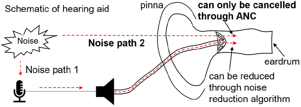
In hearing aids, noise through Path 2 can only be reduced by active noise cancellation (ANC).
This paper presents an ANC based on two sets of MEMS resonant microphone arrays (RMAs) which senses speech and noise (or undesirable sounds) separately with extremely low noise floor (albeit only near the resonance frequencies). The noise levels with and without the ANC are measured and compared. Also, automatic speech recognition (ASR) is used to test understandability of speech with and without the ANC.
II. EXPERIMENT
A. Resonant microphone arrays (RMAs)
For the ANC, we use two sets of resonant microphone arrays shown in Fig. 2. Each array is composed of multiple piezoelectric cantilever microphones with different resonance frequencies covering two frequency ranges: one between 0.8 and 5 kHz and the other between 5 and 9 kHz. The microphones provide high sensitivities and natural filtering effect near the resonance frequencies.
Fig. 2.

Photos of the fabricated RMAs (a) with resonance frequencies from 856 to 4,889 Hz to sense speech and (b) with resonance frequencies from 5,380 to 8,820 Hz to actively cancel any sound in that frequency range. (c) Photo of a resonant microphone in the array
The basic structure of each cantilever microphone [8] is 5 pm thick Si paddle, a cantilever-like structure with narrower width near the anchor (Fig. 2c). This structure reduces the footprint of each microphone compared to a traditional rectangular cantilever for a given resonance frequency. The size and resonance frequency of each microphone in the two arrays are shown in Tables 1 and 2. The gap between the edge of the microphone paddle and Si substrate is controlled as small as 20 pm to reduce the sound leak through the gap (for a good low frequency response). A patterned 0.5 μm thick piezoelectric ZnO film is only on the narrow area (near the anchor) of the paddle to convert the sound to voltage.
TABLE I.
Resonance frequency and size of the microphones in the RMA Fig. 2a.
| Leg# | Resonance freq. (Hz) | Size D (mm) |
|---|---|---|
| 1 | 856 | 2.5 |
| 2 | 1,342 | 2.3 |
| 3 | 1,759 | 2.0 |
| 4 | 2,179 | 1.8 |
| 5 | 2,591 | 1.6 |
| 6 | 3,011 | 1.5 |
| 7 | 3,458 | 1.3 |
| 8 | 3,793 | 1.2 |
| 9 | 4,356 | 1.2 |
| 10 | 4,889 | 1.2 |
TABLE II.
Resonance frequency and size of microphones in the RMA Fig. 2b.
| Leg# | Resonance freq. (Hz) | Size D (mm) |
|---|---|---|
| 1 | 5,380 | 0.90 |
| 2 | 5,940 | 0.85 |
| 3 | 6,500 | 0.85 |
| 4 | 6,760 | 0.80 |
| 5 | 7,120 | 0.80 |
| 6 | 7,580 | 0.75 |
| 7 | 8,260 | 0.72 |
| 8 | 8,600 | 0.70 |
| 9 | 8,820 | 0.70 |
The fabrication process of the device is briefly illustrated in Fig. 3. Each cantilever microphone works independently so that any of them can be combined to cover different frequency range. The microphone array shown in Fig. 2a has thirteen such resonant microphones [8], and we use ten of them with resonance frequencies 856 – 4,833 Hz to sense speech, as main speech spectrum is within 300 – 4,000 Hz. Another array (Fig. 2b) has nine microphones with resonance frequencies 5,380 – 8,820 Hz, and is used to pick up sound in that range so that we may actively cancel the sound or noise within that range.
Fig. 3.
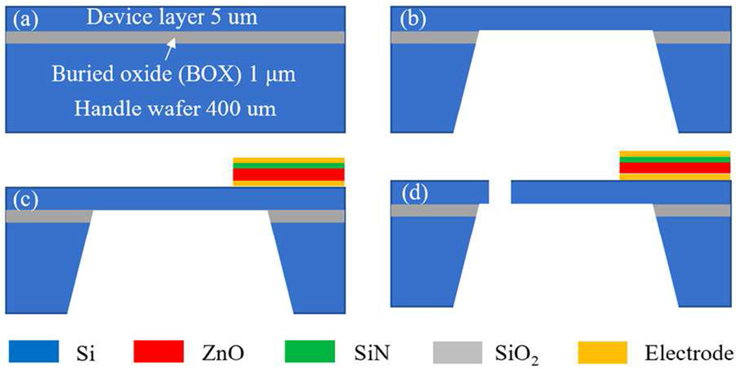
Brief fabrication process of the resonant microphone array: (a) SOI wafer; (b) patterning and etching of backside Si and buried oxide; (c) deposition and patterning of 0.2 μm sputtered Al ground, 0.5 μm sputtered ZnO, 0.1 μm PECVD SiN and 0.2 μm sputtered Al top electrode; (d) cantilever microphone release through deep reactive iron etching (DRIE)
The measured frequency response and quality factor of the resonant microphones in each array are shown in Figs. 4 and 5. The unamplified sensitivities at the resonance frequencies are higher than that of a typical commercial MEMS microphone which is usually lower than 12.5 mV/Pa. The highest unamplified sensitivity of the fabricated RMA is 202.1 mV/Pa at 856 Hz, 16 times that of the commercial MEMS microphone. The quality factors of the resonant microphones in RMA for speech sensing are 21.6 – 50.9 (Fig. 4), and those for noise cancellation are 35.7 – 75.1 (Fig. 5).
Fig. 4.
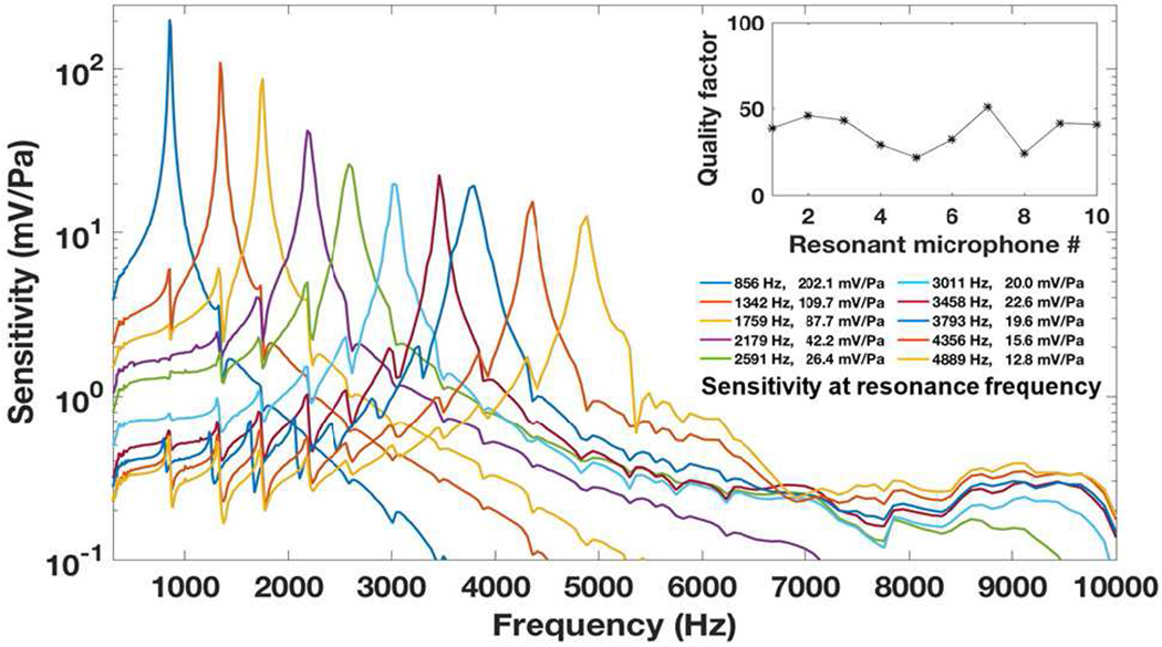
Measured frequency response of the resonant microphones to sense the speech with high unamplified sensitivity from 856 to 4,889 Hz which covers the main spectrum of speech.
Fig. 5.
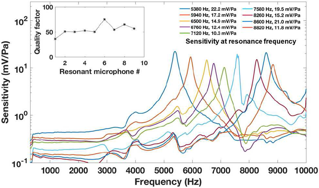
Measured frequency response of the resonant microphones to sense the high frequency noise with high unamplified sensitivity from 5,380 to 8,820 Hz for active noise cancellation in this frequency range
B. Experimental set up for ANC
The experimental setup for testing the active noise cancellation (ANC) is illustrated in Fig. 6, which mimics Fig. 1 which clearly illustrates the need for ANC to cancel out the noise through the Path 2. The target noise cancellation in this study is to actively cancel out any and every sound (whether useful or not) over 5 – 9 kHz (which is above the range where main speech information resides); in order to obtain better speech recognition, and that without presence of the high frequency (or high pitched) sounds bothering some, especially those with hyperacusis.
Fig. 6.
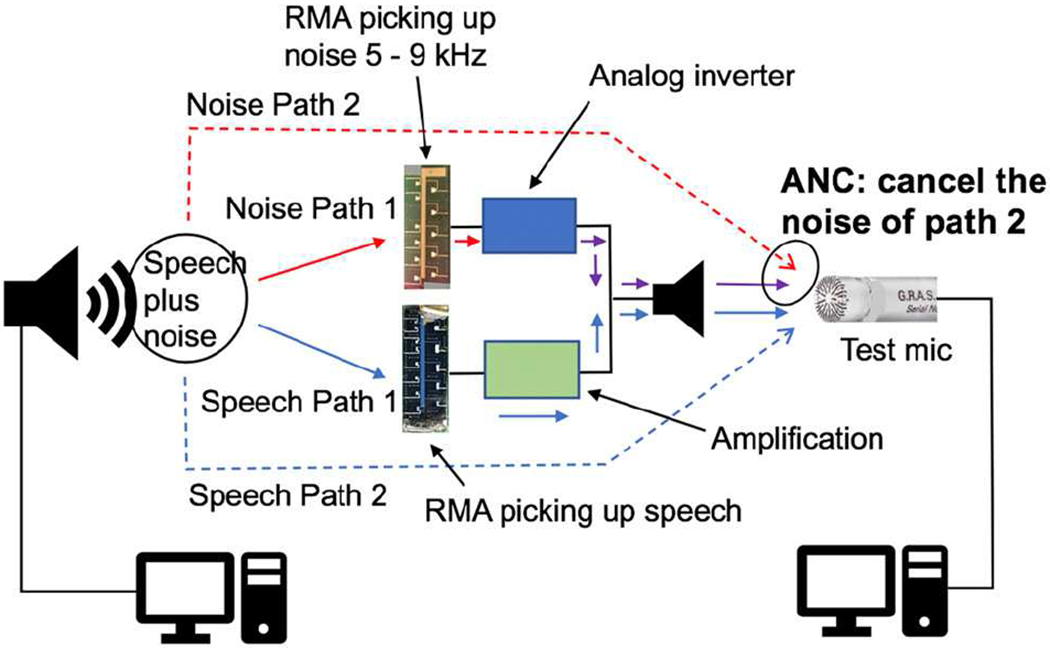
Schematic for testing the ANC with analog inverter which mimics the situation illustrated in Fig. 1.
In the experimental setup (Fig. 7), the resonant microphone array with resonance frequencies 856 – 4,889 Hz, called the speech RMA, picks up the speech over the frequency range where most of speech information is present, while the other resonant microphone array with resonance frequencies 5,380 – 8,820 Hz, called the ANC RMA, picks up all the sounds in the frequency range where very little speech information is present. The signal picked up by the ANC RMA is processed and then played to cancel the noise that would have reached the ear drum through the Path 2. A reference microphone (GRAS 40AO) mimicking the ear drum is used to test the ANC performance.
Fig. 7.
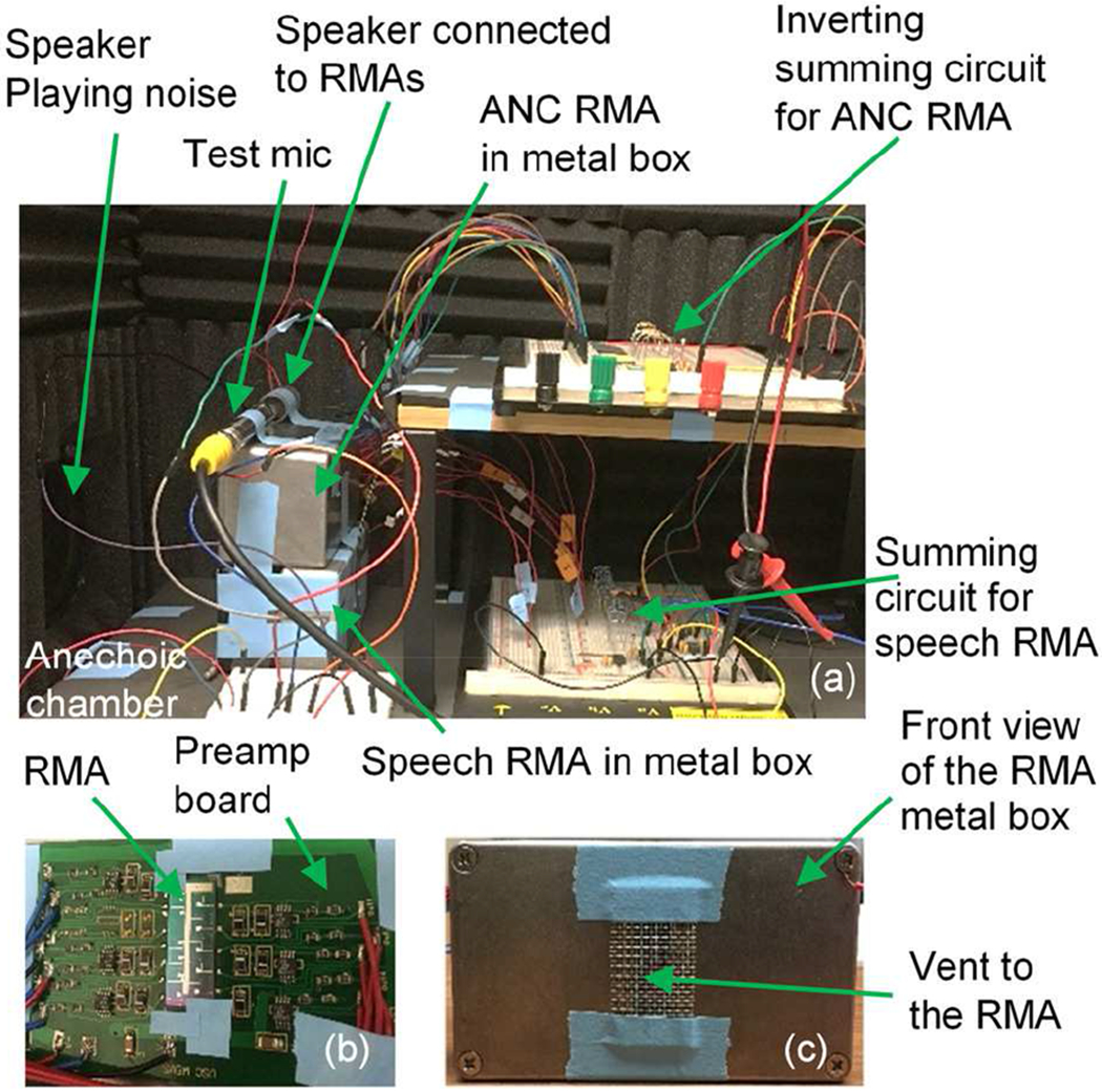
Photos of (a) the ANC experimental set up in an anechoic chamber, (b) the RMA with preamplifiers, which is placed in a metal box, (c) front view of the metal box with holes for sound transmission to RMA
For comparison, ANC with a traditional flat-band electret condenser microphone (ECM) (POM-3535L-3-LW100-R from PUI Audio, amplified sensitivity 17.8 mV/Pa, SNR 68 dB) also is implemented by replacing the ANC RMA (and its accompanying electronics) with the flat band microphone in Fig. 6 and Fig. 7a.
Analog summing and inverting circuit based on an op amp shown in Fig. 8a is connected to the ANC RMA to sum and invert the noise signals picked up by the resonant microphones to actively cancel the noise with 180° out-of-phase sound, as illustrated in Fig. 6. For ANC with a flat band microphone, a high pass (>5 kHz) op amp inverter shown in Fig. 8b is applied to the output of the flat band microphone so that only the signal beyond 5 kHz may pass through. Such a high pass filter is not required for the ANC RMA which picks up sound from 5 – 9 kHz with its resonances spread over that range, as RMA has inherent filtering in acoustic domain with high quality factor. The analog gains in Fig. 8 were optimized manually for maximum noise reduction through adjusting R11-R19 in Fig. 8a and R2 in Fig. 8b such that the amplitude of the noisecancelling sound played by the speaker may be close to that of the noise. Although adaptive (or automatic) gain control is needed for ANC in real applications, it is not necessary for comparing the analog approach based on RMA with that based on a flat-band microphone. The gain of the amplification circuit for the speech RMA can be adjusted separately without affecting ANC performance as illustrated in Fig. 6.
Fig. 8.

Schematics of (a) the analog inverter for ANC RMA and (b) the high pass inverting amplifier with fc = 5 kHz for ANC with flat band microphone.
C. Digital algorithms for ANC
Besides the ANC experiments with analog inverter described in the previous paragraphs, digital signal processing was also used on the signals picked up by the ANC RMA and the flat-band microphone to compare the various ANC approaches.
1). ANC with phase compensator for RMA
The resonant microphone can be considered to be a second order system with a transfer function H(s)
| (1) |
where k is DC gain, ω0 and Q are the resonance frequency and quality factor at resonance, respectively, and are obtained from Figs. 4 and 5 to be used with Eq. 1 for implementing the phase compensator described below. According to Eq. 1, there is a 90° phase shift at the resonance frequency, which impacts the ANC performance.
Consequently, a digital algorithm illustrated in Fig. 9 is designed to compensate the phase shift. First, we note that the resonant microphone’s transfer function converts the input signal s(n) to output signal x(n), as follows in frequency domain
| (2) |
where X(ejω) and S(ejω) are the Fourier transforms of x(n) and s(n), respectively, while H(ejω) is the transfer function of the resonant microphone.
Fig. 9.

Digital phase compensator: s(n) is the noise signal; H(s) is transfer function of the resonant microphone; y(n) is the output of the phase compensator.
If the digitized values of x(n) are flipped in time (i.e., the signal in a buffer is convoluted from right to left), the reversing order of x(n) is xinv(n), which in frequency domain is
| (3) |
where Xinv(ejω) is the Fourier transform of Xinv(n), flipped x(n). If Xinv(ejω) is passed through the transfer function of the resonant microphone H(ejω), we get
| (4) |
Then through flipping Yinv(n), which is the inverse Fourier transform of Yinv(ejω), in time domain, we have
| (5) |
Since the phase of y(n), which is the inverse Fourier transform of Y(ejω), is the same as the original noise s(n), the digital phase compensator shown in Fig. 9 restores phase shift near the resonance of the resonant microphone.
For ANC with RMA and the digital phase compensator, the gain of y(n) at 9 different channels of the ANC RMA are optimized so that the &, which is the noise energy after ANC, is minimized.
| (6) |
where s0(n) is the noise reaching to the test microphone, Gi is the gain of y(n) at different channel, G is the gain of summed y(n) for ANC. This optimization is currently implemented in a laptop computer, and takes 13 msec.
2). ANC with a digital adaptive filter
A digital adaptive filter (Fig. 10) has been used for both RMA and flat band microphone. A least mean square (LMS) optimizer is used to optimize a 101 order (100 taps) FIR (finite impulse response) causal filter, with step size of 0.1 for the gradient descent process, so that the error noise energy E(Σ(s(n) – y(n))2) may be minimized. There is a tradeoff between the convergence rate (determined by the step size) and noise reduction performance.
Fig. 10.
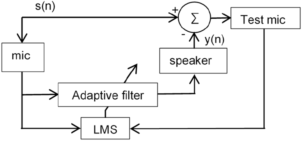
Schematic of ANC with a digital adaptive filter.
3). ANC with deep learning
Deep learning (Fig. 11) also has been applied to process the noise signal picked up by the ANC RMA and the flat band microphone to evaluate the performance of the RMA-based and flat-band-microphone-based approach ANC. The deep learning algorithm is based on temporal convolutional network (TCN) [9] which regresses the noise at the current time by tracing back 0.09 seconds for historic data picked up by the ANC microphone after training with a set of noises (e.g., white noise, mixed sinusoidal noise, etc.). During training, it converges to the best performance by tracing 11 seconds of training sounds under learning rate of 0.02.
Fig. 11.

Schematic of the deep learning with TCN for ANC
III. Results and discussion
A. ANC performance
The noise levels before and after the ANC with RMA and analog inverter are shown in Fig. 12 for white noise over 5,380 – 8,820 Hz. The noise reduction is not uniform over the frequency range. At most frequencies, the noise reduction is 0 – 10 dB. At some frequencies such as 5.985, 7.500, 8.160, and 8.500 kHz, the noise reduction is −20 to −25 dB. These frequencies are close to the resonance frequencies (vertical dash line in Fig. 12) of the ANC RMA. Thus, the resonance frequencies of the ANC RMA can be designed especially for specific noise frequencies for best noise reduction. In general, noise reduction can be improved with a larger number of resonant microphones in the ANC RMA so that noise at more frequencies can be cancelled out well. However, the size of the RMA would be larger, and there is a trade-off between ANC performance and device size. Also, the ANC with RMA can be more effective, if the phase shift issue at the microphone’s resonance frequency is compensated, as can be seen in Fig. 12 with the experimental data obtained with the digital phase compensator (Fig. 9).
Fig. 12.
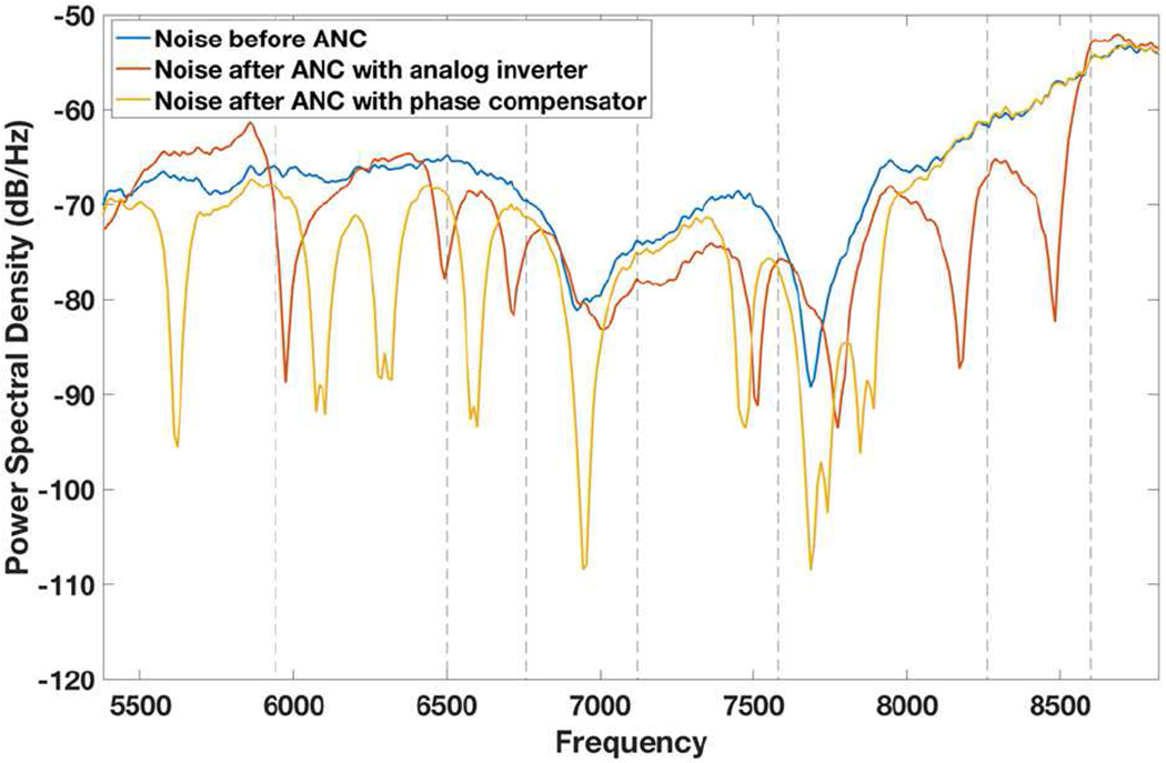
Noise power spectral densities before and after ANC with RMA, with analog inverter and with digital phase compensator.
In comparison, the noise reduction with ANC through flat band microphone is uniform but the reduction level is very limited as shown in Fig. 15. Figure 17 shows the percentage of a particular noise reduction level within this frequency range 5,380 – 8,820 for the two approaches. We can see that noise reduction of −10 to −30 dB is more often with the RMA-based approach than the flat-band-microphone-based approach.
Fig. 15.
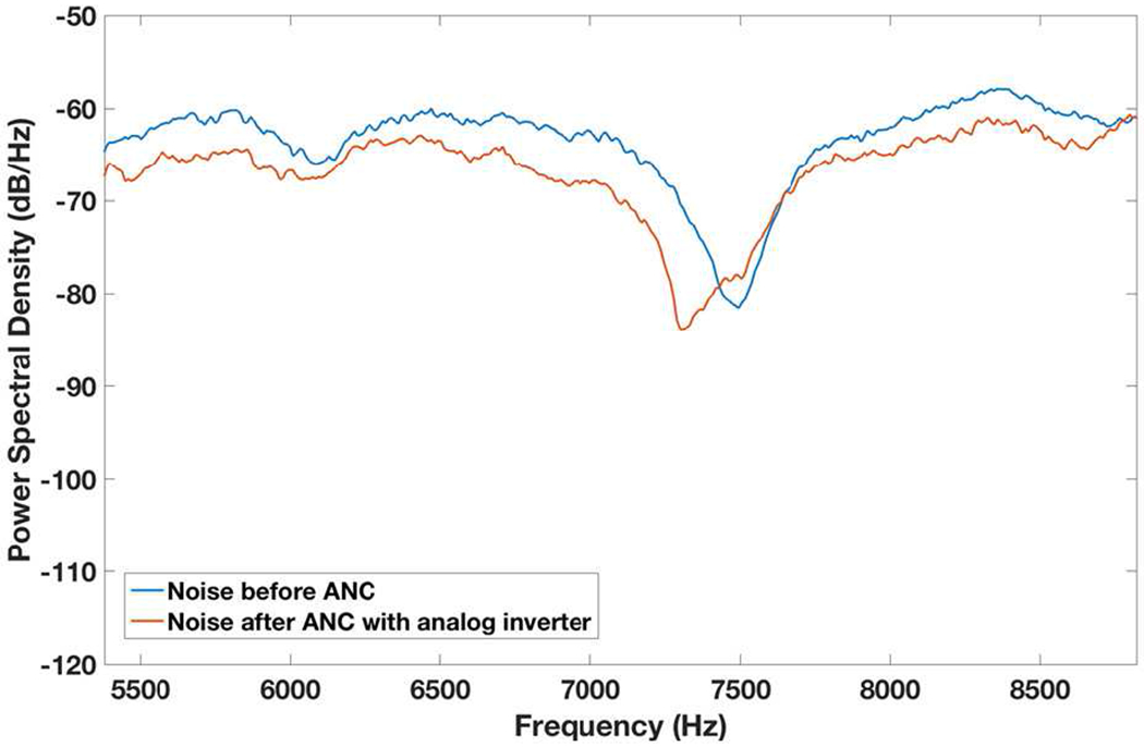
Noise power spectral density before and after ANC with flat band microphone plus analog inverter
Fig. 17.

Percentage of noise reduction levels for ANC with analog inverter for RMA and flat band microphone.
The ANC with a digital adaptive filter (Fig. 10) improves the ANC performance with both RMA and flat band microphone over the ANC with deep learning, as shown in Figs. 13 and 16. We can see that −20 dB to −10 dB noise reduction can be achieved at most frequencies for white noise over 5,380 – 8,820 Hz. However, the noise reduction with the adaptive filter is still limited when the noise signal level before ANC is low, as shown in Fig. 13 at 7.6 kHz and Fig. 16 at 7.5 kHz. In this situation, the RMA-based approach performs better than the flat-band-microphone-based approach, as shown in Fig. 14, which plots the noise change after ANC versus the noise level. The reason is that when the noise signal level is lower than the equivalent input-referred noise (or the noise floor) of the flat band microphone, the microphone is unable to pick up the noise for ANC. Thus, the highly sensitive RMA (with much lower noise floor than the flat band microphone at the RMA’s resonance frequencies) offers a means for better ANC in the case of low level of sound/noise.
Fig. 13.
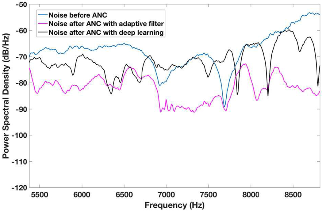
Noise power spectral densities before and after ANC with RMA plus adaptive filter and with RMA plus deep learning.
Fig. 16.

Noise power spectral density before and after ANC with flat band microphone plus adaptive filter and with flat band microphone plus deep learning.
Fig. 14.
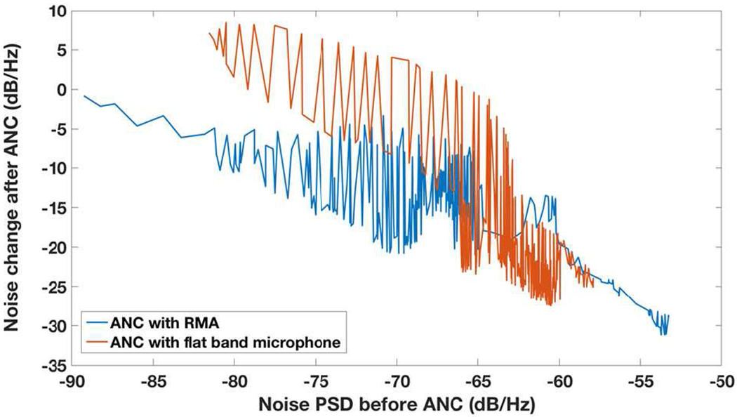
Noise change after ANC with adaptive filter for both RMA and flat band microphone vs the noise power spectral density (PSD) before ANC.
The noise reduction with the deep learning is lower than that with the adaptive filter, but can be improved with an optimized deep learning. However, deep learning technique works only for noises that can be trained into deep learning, and cannot cancel any and every kind of noise. Moreover, long training time undermines the application of deep learning to real time ANC with time-varying noises. In the case of the ANC with the adaptive filter, the noise energy reduction varies as 30, 85 and 96% with the filter-optimization time of 0.016, 0.172 and 3.127 sec, respectively. For fast time-varying noise, high convergence rate and short settling time is necessary for good ANC performance.
B. Speech recognition
The measured word error rates (WERs) of the ASR with and without the RMA-based ANC with analog inverter for both the white noise and sinusoidal noises (5.985, 7.500, 8.160, 8.500 kHz, which are close to resonance frequencies of the ANC RMA) are shown in Fig. 18. Overall, the WER with the ANC is lower than that without the ANC, as expected. The marginal improvement of WER with the ANC is the best for speech with signal-to-noise ratio (SNR) around −25 dB. As the acceptable WER is typically 25% [11], we can see that the minimum SNR acceptable without the ANC is −22 dB, while it is −26 dB with the ANC. If the frequencies of noises in real environment are not near the resonance frequencies of the ANC RMA, WER in ASR will suffer, and more resonant microphones in the ANC RMA (at the cost of larger device size) or a digital adaptive filter (e.g., Fig. 10 with its optimization time substantially reduced) may be needed.
Fig. 18.
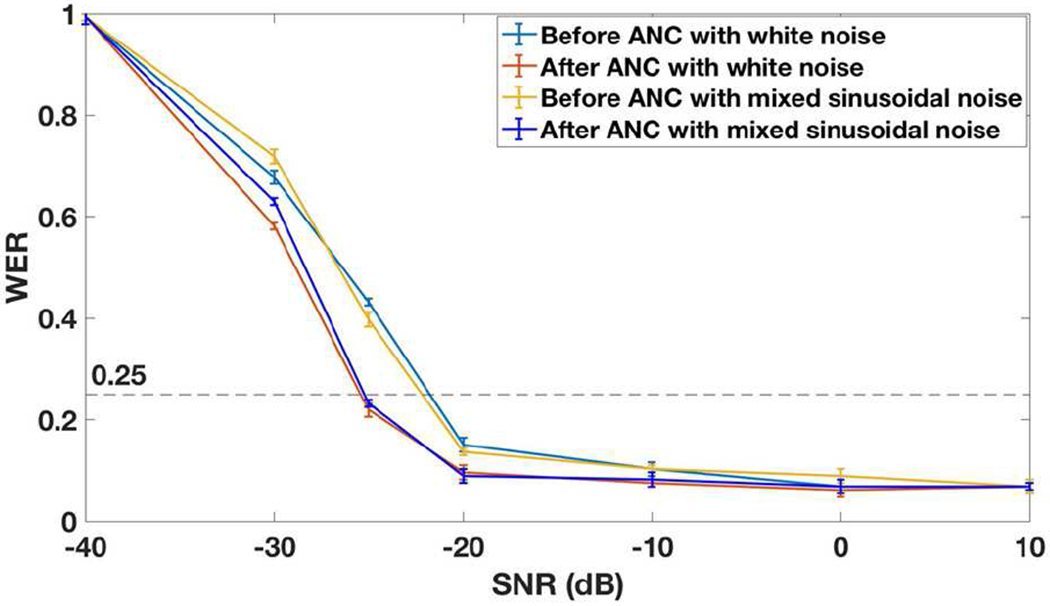
Word error rate (WER) of ASR before and after the ANC with RMA and analog inverter for the speech with different SNR (with the 70 dB SPL on the test microphone for all the speech files).
Since the Test mic (in Fig. 6) has a noise floor, the sound pressure level (SPL) of the speech also has effect on speech recognition, for a given SNR in the environment. As shown in Fig. 19, the measured WER increases with lower SPL for the same SNR of −20 dB of the speech. The worsening slope of the WER with ANC is lower than that without the ANC, as the SPL is decreased. The minimum acceptable SPL (defined by the minimum acceptable WER of 25%) is 67 dB when ANC is used, lower than 69 dB when no ANC is used. The significance of this finding is that the hearing-aid wearer can understand speech without going closer to the speaker. It is noted that the noise floor of the test microphone (in this case the reference microphone GRAS 40AO) affect the net SNR, as the SPL of the speech is reduced, for a given SNR in the environment.
Figure 19.

Word error rate (WER) of ASR before and after the ANC with RMA and analog inverter for the speech with same SNR of −20 dB but with different SPL of the speech on the test microphone.
IV. Summary
Active noise cancellation (ANC) based on two sets of MEMS resonant microphone array (RMA) (one for speech and the other for ANC) is presented, and shown to be effective in actively cancelling the noise over 5 – 9 kHz (above the range where most of speech information resides) and in improving speech recognition. Compared to a similar ANC based on a flat band microphone, ANC with RMA can cancel more noise around its resonance frequencies, because of very high sensitivities at those frequencies. The ANC performance with RMA can be improved with a digital phase compensator that takes care of the phase shift issue near the resonance frequency. Also, there is more noise reduction for ANC with RMA than flat band microphone when the noise loudness level is low. Furthermore, the ANC with RMA and analog inverter is tested for ASR as a function of (1) signal-to-noise ratio in the environment and (2) the sound pressure level of speech with two types of noises added. The ANC is shown to improve ASR performance.
Acknowledgments
This work was supported by National Institute of Health under grant number R21 DC016468
Biographies

Hai Liu (M’19) received the B.S. and M.S. degrees in materials science and engineering from the Harbin Institute of Technology, Harbin, Heilongjiang, China, in 2006. He is currently pursuing the Ph.D. degree in electrical engineering at University of Southern California, Los Angeles, CA, USA.
From 2006 to 2016, he was a senior R&D engineer in Samsung Semiconductor China R&D Co., Ltd, Suzhou, Jiangsu, China. He is the author of 8 papers and holds 5 issued patents. His research interests include developing highly sensitive MEMS microphone for electronic stethoscope, hearing aids and voice human-machine interface, human auditory system inspired MEMS acoustic sensors, and advanced electronic packaging.
Mr. Liu’s awards and honors include R&D Gold Award (2009, Samsung Electronics China), Annenberg Fellowship (2016 – 2020, University of Southern California), and Outstanding Student Paper Nominee (2020, MEMS conference).

Song Liu received the B. S. degree in sensing technology and instrumentation from Shandong University, Jinan, China, in 2012, and the Ph.D. degrees in control science and engineering from University of Chinese Academy of Sciences, Beijing, China, and City University of Hong Kong (CityU), HK, respectively, in 2017. From June 2017 to 2018, he served as a postdoctoral fellow in Robot Vision Research Lab in the department of mechanical engineering, CityU.
Dr.Liu is currently working as a postdoctoral scholar in MEMS Group in University of Southern California, CA, USA. He will be an assistant professor in School of Information Science and Technology, ShanghaiTech University, Shanghai, China. His current research interests include ultrasonic MEMS, robotics sensors, visual servo control, and robot learning. Please visit his Google Scholar for more relevant publications at https://scholar.google.com/citations?user=n2rWxVQAAAAJ&hl=en.

Anton A. Shkel (M’10) received the B.S. degree in electrical engineering from the University of California at Los Angeles, CA, USA, and the M.S. and Ph.D. degrees in electrical engineering from the University of Southern California at Los Angeles, in 2018.
His research interests include acoustic MEMS transducers, beamforming arrays, and ubiquitous and wearable sensing, and their integration with machine learning processing techniques. He is a recipient of the USC-Chevron Fellowship in 2013. He was also a student representative of the Administrative Committee of the IEEE Ultrasonics, Ferroelectronics, and Frequency Control Society. Dr. Shkel is currently a Senior Wireless Systems consultant with Facebook, working on next-generation wireless technologies for wearable devices and telecom infrastructure.

Eun Sok Kim (M’91-SM’01-F’11) received the B.S., M.S., and Ph.D. degrees in electrical engineering from the University of California at Berkeley, CA, USA, in 1982, 1987, and 1990, respectively.
He was with the IBM Research Laboratory, San Jose, CA, USA, NCR Corporation, San Diego, CA, USA, and Xicor Inc., Milpitas, CA, USA, as a Co-Op Student, Design Engineer, and Summer- Student Engineer, respectively. From Spring 1991 to Fall 1999, he was with the Department of Electrical Engineering, University of Hawaii at Manoa, as a Faculty Member. He joined the University of Southern California (USC) at Los Angeles, Los Angeles, in Fall 1999, where he is currently a Professor of the Ming Hsieh Department of Electrical and Computer Engineering. From July 1, 2009 to June 30, 2018, he chaired the Electrophysics division of the department, and oversaw a net tenure-track-faculty growth of 2.5 (from 15.25 to 17.75), 6.5 new tenure-track-faculty hires, 3 new tenure-track-faculty offers and acceptances in the last year as the chair. During his tenure as the chair, US News’ ranking raw score on USC EE’s Graduate Program rose from 3.9 to 4.2 (out of 5.0).
He is an expert in piezoelectric and acoustic MEMS as well as electromagnetic vibration-energy harvesters (VEHs), having published about 250-refereed papers in the fields. He holds 16 issued US patents in piezoelectric and acoustic MEMS as well as in VEHs.
Dr. Kim is a Fellow of the Institute of Physics. He has received the Research Initiation Award (1991–1993) and the Faculty Early Career Development Award (1995–1999) from the National Science Foundation. He has also received the Outstanding Electrical Engineering Faculty of the Year Award from the University of Hawaii at Manoa in 1996 and the IEEE TRANSACTIONS ON AUTOMATION SCIENCE AND ENGINEERING 2006 Best New Application Paper Award. He currently serves as an Editor for the IEEE/ASME JOURNAL OF MICROELECTROMECHANICAL SYSTEMS.
Contributor Information
Hai Liu, Electrical Engineering Department, University of Southern California, Los Angeles, CA 90089 USA.
Song Liu, Electrical Engineering Department, University of Southern California, Los Angeles, CA 90089 USA.
Anton A. Shkel, Electrical Engineering Department, University of Southern California, Los Angeles, CA 90089 USA. He is now with Facebook, Menlo Park, CA 94025 USA.
Eun Sok Kim, Electrical Engineering Department, University of Southern California, Los Angeles, CA 90089 USA.
References
- [1].Hoffman HJ, Dobie RA, Losonczy KG, Themann CL, and Flamme GA, “Declining Prevalence of Hearing Loss in US Adults Aged 20 to 69 Years,” JAMA Otolaryngology Head Neck Surg, vol. 143, no. 3, pp. 274–285, March. 2017. [DOI] [PMC free article] [PubMed] [Google Scholar]
- [2].Picou EM, “MarkeTrak 10 (MT10) Survey Results Demonstrate High Satisfaction with and Benefits from Hearing Aids,” Seminars in Hearing, vol. 41, no. 01, pp. 021–036, October. 2020. [DOI] [PMC free article] [PubMed] [Google Scholar]
- [3].Chung K, “Challenges and Recent Developments in Hearing Aids: Part I. Speech Understanding in Noise, Microphone Technologies and Noise Reduction Algorithms,” Trends in Amplification, vol. 8, no. 3, pp. 83–124, January. 2004. [DOI] [PMC free article] [PubMed] [Google Scholar]
- [4].Shkel AA, Baumgartel L, and Kim ES, “A resonant piezoelectric microphone array for detection of acoustic signatures in noisy environments,” in Proc. IEEE MEMS, Estoril, Portugal, 2015, pp. 917–920. [Google Scholar]
- [5].Ho C-Y, Shyu K-K, Chang C-Y, and Kuo SM, “Integrated active noise control for open-fit hearing aids with customized filter,” Applied Acoustics, vol. 137, pp. 1–8, August. 2018. [Google Scholar]
- [6].Serizel R, Moonen M, Wouters J, and Jensen SH, “A zone of quiet based approach to integrated active noise control and noise reduction in hearing AIDS,” in Proc. IEEE WASPAA, New Paltz, NY, USA, 2009, pp. 229–232. [Google Scholar]
- [7].Dalga D and Doclo S, “Combined feedforward-feedback noise reduction schemes for open-fitting hearing aids,” in Proc. IEEE WASPAA, New Paltz, NY, USA, 2011, pp. 185–188. [Google Scholar]
- [8].Baumgartel L, Vafanejad A, Chen S-J, and Kim ES, “Resonance-Enhanced Piezoelectric Microphone Array for Broadband or Prefiltered Acoustic Sensing,” J. Microelectromech. Syst, vol. 22, no. 1, pp. 107–114, February. 2013. [Google Scholar]
- [9].Lea C, Flynn MD, Vidal R, Reiter A, and Hager GD, “Temporal Convolutional Networks for Action Segmentation and Detection,” in Proc. IEEE CVPR, Honolulu, HI, USA, 2017, pp. 156–165. [Google Scholar]
- [10].IBM Watson speech to text service. Available: https://speech-to-text-demo.ng.bluemix.net, Accessed on: May 10th 2020.
- [11].Munteanu C, Penn G, Baecker R, Toms E, and James D, “Measuring the Acceptable Word Error Rate of Machine-Generated Webcast Transcripts,” in Proc. ICSLP, Pittsburgh, PA, USA, pp. 157–160, 2006. [Google Scholar]


