Abstract
Permanent magnet localization (PML) is designed for applications requiring non-line-of-sight motion tracking with millimetric accuracy. Current PML-based tongue tracking is not only impractical for daily use due to many sensors being placed around the mouth, but also requires a large training set of tracer motion. Our method was designed to overcome these shortcomings by generating a local magnetic field and removing the need for the localization to be trained with tracer rotations. An inertial measurement unit (IMU) is used as a tracer that moves in a local magnetic field generated by a magnet strip. The magnetic strength can be optimized to enable the strip to be placed further away from the tracer, thus hidden from view. The tracer is small (6×6×0.8 mm3) to reduce hindrance to natural tongue movements, and the strip is designed to be worn as a neckband. The IMU’s magnetometer measures the local magnetic field which is compensated for the tracer’s orientation by using the IMU’s accelerometer and gyroscope. The orientation-compensated magnetic measurements are then fed into a localization algorithm that estimates the tracer’s 3D position. The objective of this study is to evaluate the tracking accuracy of our method. In a 8×8×5 cm3 volume, positional errors of 1.6 mm (median) and 2.4 mm (third quartile, Q3) were achieved on a tracer being rotated ±50° along both pitch and roll. These results indicate this technology is promising for tongue tracking applications.
Index Terms—: inertial measurement unit, magnet, magnetic localization, motion tracking, neural network, orientation estimation, permanent magnet localization, tongue tracking
I. Introduction
MOTION tracking technologies play a vital role in various applications such as robotics, sports, virtual/augmented reality, and entertainment. Chief among them is the tracking of body motion for medical applications which, for example, is included as part of assistive technologies to assist in the rehabilitation of physical disabilities, or as an alternative control used by people with quadriplegia. However, tracking the motion of the tongue remains a challenge despite its valuable use in speech rehabilitation [1], [2], as part of a silent speech interface [3]–[5], and as an alternative method of controlling devices [6]. There are many technical difficulties in tracking the motion of the tongue that render most available motion tracking systems unsuitable. For instance, opticalbased tracking (i.e. computer vision, reflective markers) cannot be used due to the lack of visibility of the inside of the mouth, and any suitable technology must be minimally obtrusive to avoid impeding natural tongue motion.
Commercially available tracking technologies such as the Electromagnetic Articulograph (EMA) are well known for tracking with millimetric accuracy the 3D position and 2D orientation of multiple tracers on the tongue [7]–[9]. EMA functions by emitting a strong electromagnetic field that surrounds the user’s oral cavity in which coil-like tracer(s) are glued on the tongue [10]. EMA is generally considered the most accurate tongue tracking system currently available, but its use is primarily restricted to speech science research because its limitations include a lack of portability due to the need for large electromagnetic transmitters and a high cost. The Electropalatograph (EPG) detects the points of contact between the tongue and the palate using electrodes embedded in an over-the-palate mouthpiece, enabling a discretized 2D view of the tongue surface [11]. EPG is mainly used in speech therapy [12] because its lack of continuous motion tracking prevents its widespread use since many phonemes are produced without palatal contact. Ultrasound Tongue Imaging (UTI) relies on high frequency sound waves to generate a 2D image of the sagittal plane of the oral cavity [13]. Although the cross-section of the tongue is captured, the tongue tip is usually not visible on the images due to the hyoid and/or the jaw bone [14]. Additionally, the ultrasound probe must be held under the user’s jaw which is not hands-free and can restrict jaw motion during speech.
More recently, there has been a growing body of research on the development of a permanent magnet localization (PML) method to track the motion of a small magnet [15]–[17]. Tongue tracking was achieved by placing the magnet on the tongue [18], [19]. The basic principle of PML relies on capturing the magnetic field, generated from the magnet, by an array of magnetometers. The changes in the magnetic field due to the motion of the magnet are fed into a localization algorithm that estimates the magnet’s position and orientation. PML has the potential to overcome many of the shortcomings of the current tongue tracking technologies since the tracer (i.e. magnet) is small enough to not be obtrusive, provides continuous tracking in the whole 3D space, and is capable of providing millimetric tracking accuracy that is required for typical tongue tracking applications such as speech recognition [10]. However, in its usual design, PML has significant limitations that hinder its practical use for tongue tracking. For instance, its localization algorithm requires input from multiple magnetometers which must be placed close to the mouth to measure the weak magnetic field produced by the small magnet. These magnetometers must remain fixed in place to provide a stable frame of reference which requires these sensors to be mounted on a headset that can be cumbersome in activities of daily living and subject to social stigma. Using a larger magnet is not a solution because the natural motion of the tongue should not be impeded which causes this restriction on the distance between the magnet and the magnetometers. Additionally, PML is incapable of tracking multiple magnets since the magnetic field generated by each magnet cannot be uniquely measured or identified.
The tongue tracking system proposed in this paper aims to improve upon the shortcomings of existing technologies. Specifically, our portable system has been designed for use in activities of daily living, and to enable multiple tracers to be tracked simultaneously to enhance its tongue tracking capabilities for speech applications. As illustrated in Fig. 1, our technology centers around the use of an inertial measurement unit (IMU), as the tongue tracer, that moves in a local magnetic field generated by a magnet strip composed of an array of permanent magnets. An IMU combines into one package a magnetometer, an accelerometer, and a gyroscope. The novelty of our system comprises the implementation of a reverse PML in which the local magnetic field is constant but the magnetometer is moving within this field. Importantly, our method allows us to shape the local magnetic field without changing the features of the tracer (e.g. dimension, shape). More specifically, the magnetic field intensity can be increased by adding more magnets to the strip, and/or increasing their size, which enables the strip to be placed further away from the user’s head. For example, the strip can be hidden in a neckband and thus would not require a bulky, cumbersome headset to be worn. Tracers can be tracked independently because each tracer provides its own position and orientation information. Additionally, the accelerometer and gyroscope readings are used to estimate the orientation of the tracer to re-orient the sensor’s magnetic field reading to a reference frame. The orientation-compensated magnetic field is then used to estimate the position of the tracer by a feedforward neural network. Although the end goal is to design wireless tracers, a wired tracer connected to a controller is used at this stage to demonstrate the proof-of-concept of our novel tracking method. In this paper, the objective is to evaluate the tracking accuracy of our system in a volume greater than an typical oral cavity (8×8×5 cm3) with a tracer being rotated by ±50° for both pitch and roll, which are the rotations of interest for the tongue.
Fig. 1.
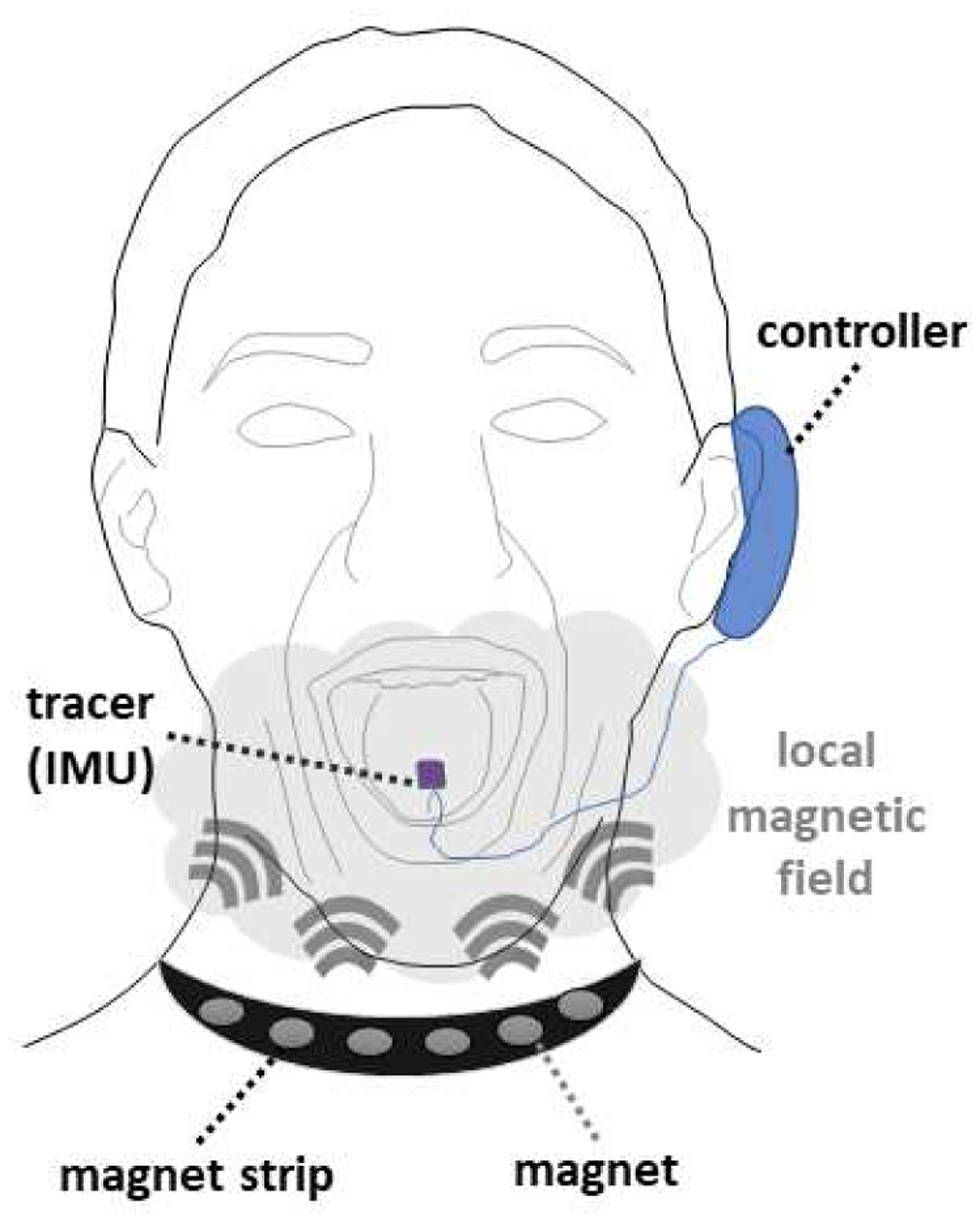
Overview of our tongue tracking system composed of a magnet strip that produces a local magnetic field, a tracer comprising an IMU, and a controller that transmits the IMU’s data to a localization algorithm that estimates the 3D position and 3D orientation of the tracer.
The rest of the paper is organized as follows: Section II provides a detailed description of our tracking method, Section III describes our data collection setup, Section IV presents our results on tracking accuracy, and Section V concludes by summarizing the significance and impact of this work.
II. Tracking Method
An overview of our tracking method is provided in Fig. 2 and can be split into the following processes: (A) generating raw data from the tracking hardware which are (B) processed to output calibrated data before being used to estimate (C) the orientation and (D) the position of the tracer. These processes are described in more details in the subsections below.
Fig. 2.
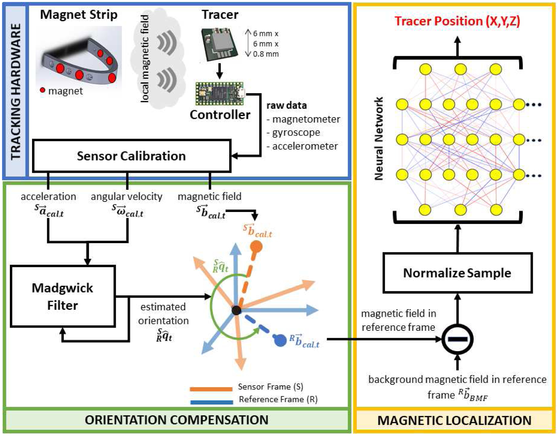
Overview of our tracking method based on a magnetic localization with orientation compensation of the magnetic field measured by the tracer’s magnetometer. The orientation of the tracer is estimated from the angular velocity and acceleration provided by its IMU and processed by a Madgwick filter. The magnetic localization is based on a neural network that estimates the tracer’s 3D position.
A. Tracking Hardware
The tracking hardware comprises a magnet strip, a tracer, and a controller. The magnet strip is a custom-designed and 3D-printed semi-ellipse with a length of 6 cm and a width of 7 cm. In this version, five permanent magnets are evenly distributed around the strip as shown in Fig. 2 (top left). Each magnet (D32-N52, K&J Magnetics, Pipersville, Pennsylvania) is cylindrical, N52 grade, and measures 4.8 mm in diameter and 3.2 mm in thickness. Because of the geometric arrangement of the magnets, the magnet strip generates a unique and local magnetic field. The dimensions, numbers, position, and orientation of the magnets are chosen empirically and have not yet been optimized for performance. Our objective in this work is to provide a proof-of-concept rather than an exhaustive study of the influence of all these parameters on the tracking accuracy. Therefore, better performance could potentially be obtained in the future.
The tracer is based on an LSM9DS1 inertial measurement unit (STMicroelectronics, Geneva, Switzerland) that measures 3-axis acceleration, 3-axis angular velocity, and 3-axis magnetic field. This IMU is embedded in a custom printed circuit board (PCB) with a size of 6×6×0.8 mm3. When used on the tongue, the tracer is coated with a bio-compatible material and attached using an FDA-approved dental adhesive such as PeriAcryl (GluStitch Inc., Delta, British Columbia, Canada). The tracer is wired to a controller composed of a Teensy microcontroller (PJRC, Sherwood, OR, USA) and a custom PCB to facilitate the connection to the tracer. Custom firmware was developed for obtaining the IMU’s data using I2C communication protocol and transmitting raw data packets to a host computer every 10 ms for further processing.
B. Sensor Calibration
Because our application requires tracking with millimetric accuracy, the IMU must be calibrated to compensate for the non-idealities that are inherent to any sensor. To calibrate the accelerometer , an ellipsoid fit method was used to provide a 3×3 gain matrix (Ga) and a 3×1 offset vector [20]. Regarding the gyroscope , a computer vision method based on colored markers was developed to estimate the angular position of the IMU relative to a reference point. These angles were used as reference values to derive the optimal gain matrix (Gω) and offset bias using a least square error method on the estimated angles by the gyroscope. Finally, the magnetometer was calibrated by randomly rotating the IMU in all orientations. The ellipsoid described by the 3-axis magnetic readings was then generated using an ellipsoid fit method [21] that also returns a 3×3 gain matrix (Gm) and a 3×1 offset bias . The resulting sensor calibration is summarized below as a set of linear transformations,
| (1) |
| (2) |
| (3) |
C. Orientation Compensation
A primary challenge for magnetic localization on a moving (wearable) system is the cancellation of the background magnetic field (BMF). The BMF is composed of the Earth’s magnetic field, which varies not only with location on Earth but also with time [22], and any surrounding magnetic sources (e.g. ferromagnetic materials). In traditional PML, the magnetometers are fixed in place which simplifies the BMF cancellation process by capturing the BMF with no magnet in the vicinity of the sensors [18], [19]. However, in a movable setup, the BMF can be seen as a rotating vector in a magnetometer’s viewpoint. Therefore, the magnetometer’s orientation must be known to cancel the BMF which is the main reason for the use of an IMU rather than solely a magnetometer in our tracer.
The added benefit of using an IMU is to circumvent the need to include the tracer’s orientation as part of the training of the localization algorithm. Indeed, the magnetic field read by a magnetometer is dependent on both position and orientation of the magnetic source. In traditional PML, the magnet is rotated in various orientations when training a localization algorithm [19] which makes the resulting model more complex and likely less accurate in practice since different combinations of position and orientation produce a same magnetic field (refer to section IV-B). Since our tracer is an IMU, its orientation can be estimated on its own and used to reduce the number of variables to be estimated by the magnetic localization model from 6 (3 positions and 3 angles) down to 3 positions only.
The Madgwick filter was chosen to estimate the tracer’s orientation due to its simplicity and efficiency. The orientation is expressed as the rotation from the sensor frame (S) to a reference frame (R) set to be orthogonal to Earth’s gravity vector which results in an absolute value of 0° for pitch and roll. Because the magnetometer is already used for magnetic localization and in the presence of a strong local magnetic field, the tracer’s yaw cannot be determine with absolute value by estimating the tracer’s heading using the Earth’s magnetic poles. Therefore, in our reference frame, the zero yaw is set to be aligned with the major axis of our magnet strip. The orientation is represented as a quaternion , estimated from the calibrated acceleration and angular velocity, and a tuning parameter β sets the robustness of the filter against sensor noise. For our IMU, a β value of 0.071 results in an estimation accuracy of 1.09°, 1.04°, and 1.10° root-mean-square errors for pitch (θ), roll (φ), and yaw (ψ), respectively.
D. Magnetic Localization
The main purpose of our orientation-compensated magnetic localization is to use the estimated orientation to rotate the measured magnetic field from the sensor frame to our reference frame using the standard equation for quaternion rotation,
| (4) |
where ⊗ and * denotes quaternion multiplication and conjugate, respectively.
The same rotation is applied to the BMF which is collected once before the start of a data collection and with no magnet strip in the tracer’s vicinity. Once both are in the same reference frame, the BMF is subtracted from the magnetic field, and the resulting orientation and BMF compensated magnetic field is fed into a feedforward neural network responsible for estimating the tracer’s 3D position. Prior to being fed into the neural network, the magnetic values are normalized to be in the range of ±1.0.
The training of the neural network was performed by collecting magnetic samples of the tracer traversing a trajectory with predefined positions as the reference. The L2 norm of the difference between the 3D position estimated by the model and its reference was used as the loss function (Epos) to be minimized during training,
| (5) |
A validation set was used to prevent overfitting to the training set by stopping the training of the neural network when the validation Q3 error did not improve after 100 epochs. It was found empirically that the architecture of the neural network that provides the lowest errors is as follows: 3 hidden layers, 50 neurons per layer, exponential linear unit as the activation function, and RMSprop as the optimizer with 256 batch size and 0.05 learning rate.
III. Data Collection Setup
To collect the datasets needed to train the neural network and evaluate the tracking accuracy of our method, a 5D positioning stage was designed to enable the tracer to be positioned and oriented to desired values with great precision. More details are provided in the following subsections.
A. 5D Positioning Stage
A similar 5 degree-of-freedom positioning stage as used in our previous work [19] has been redesigned for this study (Fig. 3). The linear stage comprises three motorized XSlides (Velmex Inc., Bloomfield, NY, USA) that can position the tracer in the 3D space (X, Y, and Z) with a reported accuracy of 76 m. The rotational stage is capable of orienting the tracer along its pitch and roll thanks to a pulley/belt system driven by two stepper motors in half-step mode, resulting in an accuracy of 0.9°. In the current design, the yaw cannot be changed because of many practical issues. Chief among them is the need for any motor to be placed far enough from the tracer (>15 cm) to prevent their induced magnetic field to be read by the magnetometer. This prevents any practical design based on standard motors, but could be overcome in the future with the use of nonmagnetic piezoelectric motors if they are more affordable.
Fig. 3.
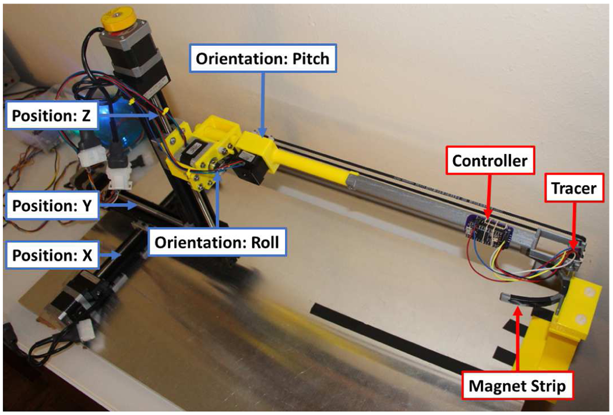
5D positioning stage that can place a tracer at a desired 3D position and 2D orientation (pitch and roll).
B. Reference Trajectories
Training and evaluating the accuracy of a neural network in estimating the position of the tracer require a training, validation, and testing set (Fig. 4). These datasets are continuous trajectories inscribed in a volume of 8×8×5 cm3 which is wider than most typical oral cavities [23], [24] and thus adequate for our tongue tracking application. The number of magnetic samples collected for the training set is ~378,000, validation is ~285,000, and testing is ~265,000. The validation set follows a similar trajectory than the training set but with a positional shift in each axis to ensure that the model will not overfit to the training set. The testing set is a unique trajectory designed to randomly sample the volume, traverse positions unseen in the training and validation sets, and represent curved movement similar to that of the tongue.
Fig. 4.
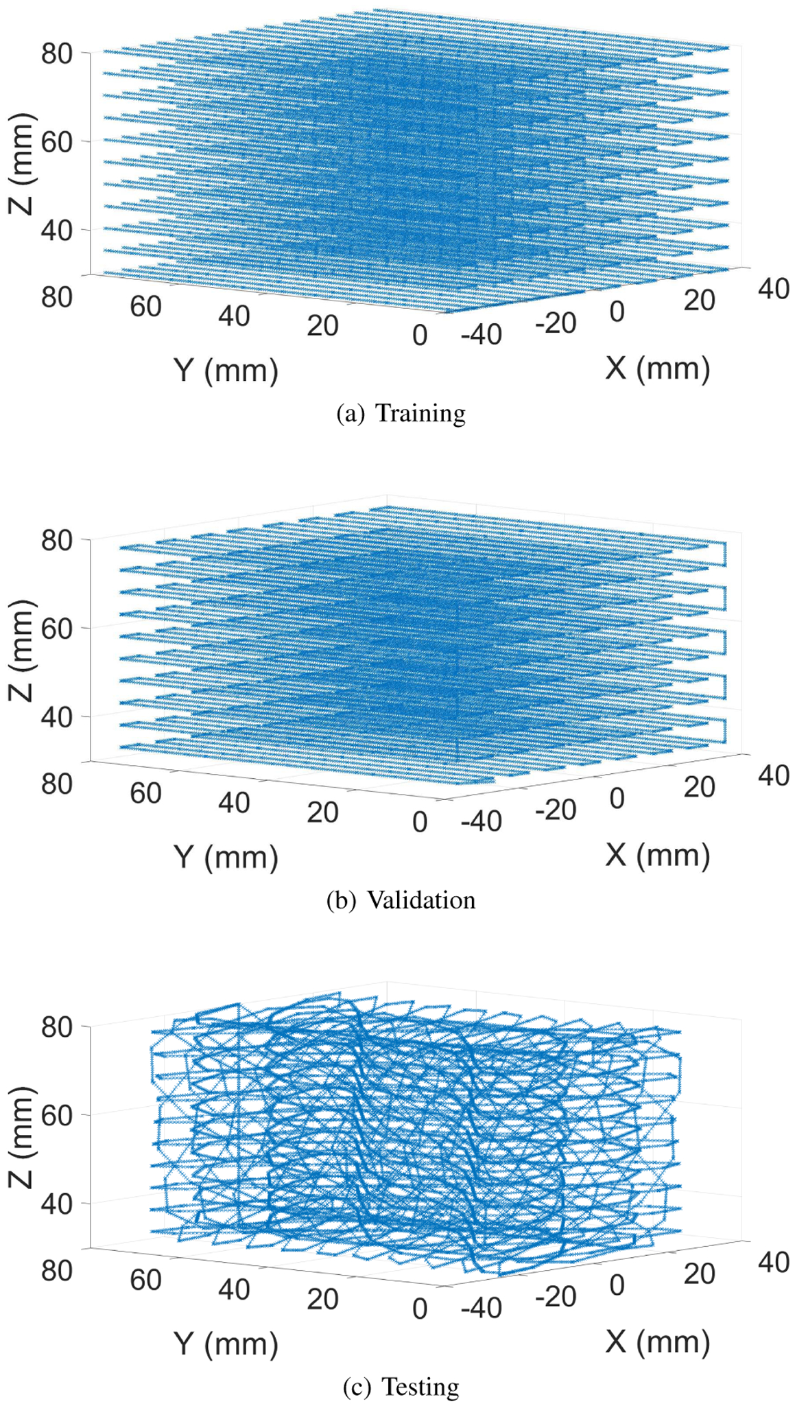
3D positions of the trajectories used for (a) training, (b) validation, and (c) testing of the neural network.
C. Comparative Assessment of Tracking Accuracy
The objective of our orientation compensation method is to reduce the complexity of the model that the neural network must learn by removing the need to account for the orientation of the tracer. To evaluate this objective, there are three assumptions that can be tested: (1) a model trained with trajectories that do not include any rotation of the tracer should generalize well to datasets with compensated rotations, (2) the model should provide a greater tracking accuracy than that of a neural network that must learn the relationship between the magnetic measurements and both 3D position and 3D (uncompensated) rotation of the tracer, and (3) the model should provide a similar level of tracking accuracy than a model trained with compensated rotations.
To validate these assumptions, the neural network described in section II-D is trained with different datasets that were collected by traversing the reference trajectories first without any rotation (Fig. 5a, top row), and then traversed again with the tracer being rotated with varying pitch and roll (Fig. 5a, center row). For both rotations, the angles are following a sinusoidal waveform with a ±50° amplitude but different frequencies to generate many combinations of pitch and roll values. To evaluate the effect of our orientation compensation method, the magnetic measurements of the trajectories with a rotated tracer are compensated (Fig. 5a, bottom row).
Fig. 5.
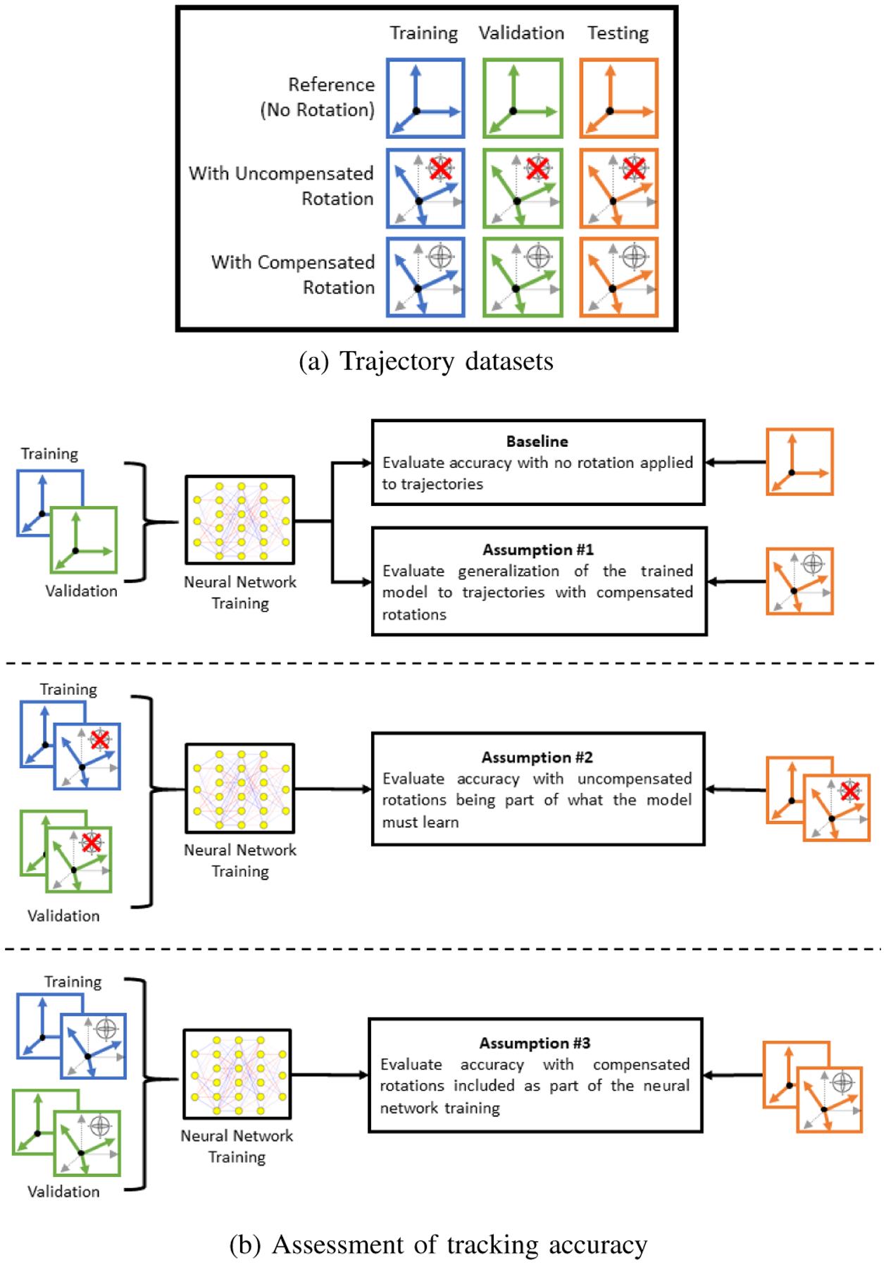
Comparative analysis of the tracking accuracy of a neural network trained with different datasets that are selected to validate specific assumptions.
A baseline of tracking accuracy (Fig. 5b, top) is first evaluated to compare our assumptions against. This baseline is composed of a neural network that is trained and tested with the datasets that do not contain rotation. The resulting model is then tested with the testing set with compensated rotation to validate our first assumption. Secondly, a neural network is trained and tested with uncompensated rotations to validate our second assumption. Finally, our third assumption is validated by training and testing a neural network with compensated rotations.
IV. Results & Discussion
This section presents the results of the comparative assessment of tracking accuracy of our system. Using the same metric as used in our previous work [19], the accuracy is represented as a positional error which is the L2 norm of the difference between the actual and estimated 3D position of the tracer, as expressed in (5). The results for each assumption is presented and discussed in a subsection below, with the positional errors shown as a heat map for the testing sets and as box plots to facilitate their analysis and comparison.
A. Tracking Accuracy for Model Trained Without Rotation
The positional errors of this model is shown in Fig. 6 with the training set having a median and Q3 values of 1.8 mm and 2.4 mm, respectively. The validation set has a median error of 1.7 mm and a Q3 error of 2.4 mm. We can observe that overfitting did not occur since the errors for validation and training sets are similar. The baseline accuracy of our system is estimated from the reference testing set with a median error of 2.0 mm and a Q3 of 2.8 mm. Overall, these results show that 75% of the errors are within 3 mm for any position of the tracer in a volume of 8×8×5 cm3.
Fig. 6.
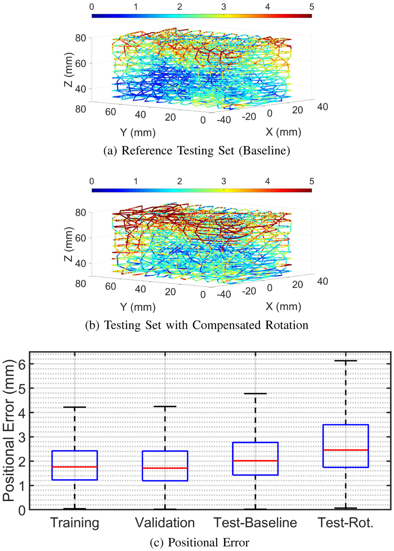
Positional errors of the baseline model shown as a heat map for the (a) reference testing set, and (b) testing set with compensated rotation. A box plot of all errors are provided in (c).
While trained on trajectories without rotation, this model generalizes well to the testing set containing compensated rotations since the median error (2.5 mm) and Q3 (3.5 mm) are only ~0.5 mm greater than the baseline.
It is consistently observed that the tracking accuracy is better in the lower and center parts of the volume. However, the accuracy tends to worsen with increased Z-axis position which can be explained by the tracer moving further from the magnet strip, resulting in a reduced signal-to-noise ratio due to a weaker magnetic field. A feature of our system is the ability to adjust the magnetic strength of the local magnetic field by varying the number, size, and geometric arrangement of the magnets in the strip. Such optimization of the magnetic strip has the potential to reduce the errors observed with higher Z values.
B. Tracking Accuracy for Model Trained with Uncompensated Rotation
The positional errors for a model trained and tested on trajectories with an uncompensated rotating tracer are provided in Fig. 7. These errors are significantly higher with a median centered around 5 mm and Q3 values greater than 10 mm. Although a better accuracy could potentially be achieved with a more complex architecture for the neural network, the values of these reported errors are consistent throughout our empirical evaluations of simple feedforward neural networks with varying number of neurons (10–100), number of layers (1–4), activation functions, along with other hyper-parameters. Since increasing the size of the neural network and changing various hyper-parameters did not have any significant effect on the tracking accuracy, this provides evidence in support of our second assumption that using an orientation compensation method to reduce the complexity of the model to be learned results in more accurate tracking.
Fig. 7.
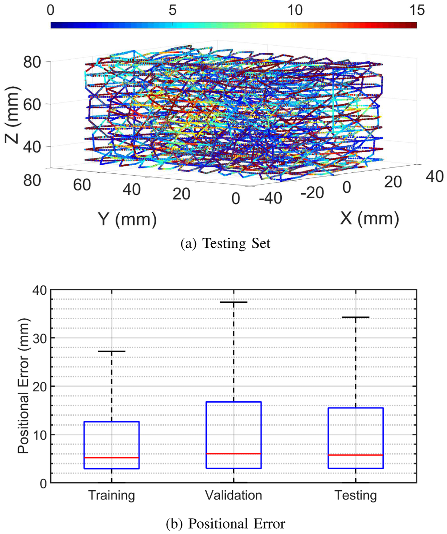
Positional errors of the model trained with uncompensated rotation shown (a) as a heat map for its testing set, and (b) as a box plot of all errors.
C. Tracking Accuracy for Model Trained With Compensated Rotation
Fig. 8 shows that this model has similar positional errors than our baseline for its training set (median: 1.8 mm, Q3: 2.9 mm), validation set (median: 1.7 mm, Q3: 2.5 mm), and testing set (median: 1.6 mm, Q3: 2.4 mm). These results provide additional evidence for our second assumption since compensating for orientation facilitates the learning of the neural network by simplifying the underlying model. Our third assumption is somewhat valid because although this model performs better at generalizing to trajectories with rotation than the baseline model, the errors are only decreased by ~1 mm. Therefore, one could consider collecting trajectories without a rotating tracer while not significantly decreasing accuracy if, for example, a large volume must be sampled or a rotational stage is not available.
Fig. 8.
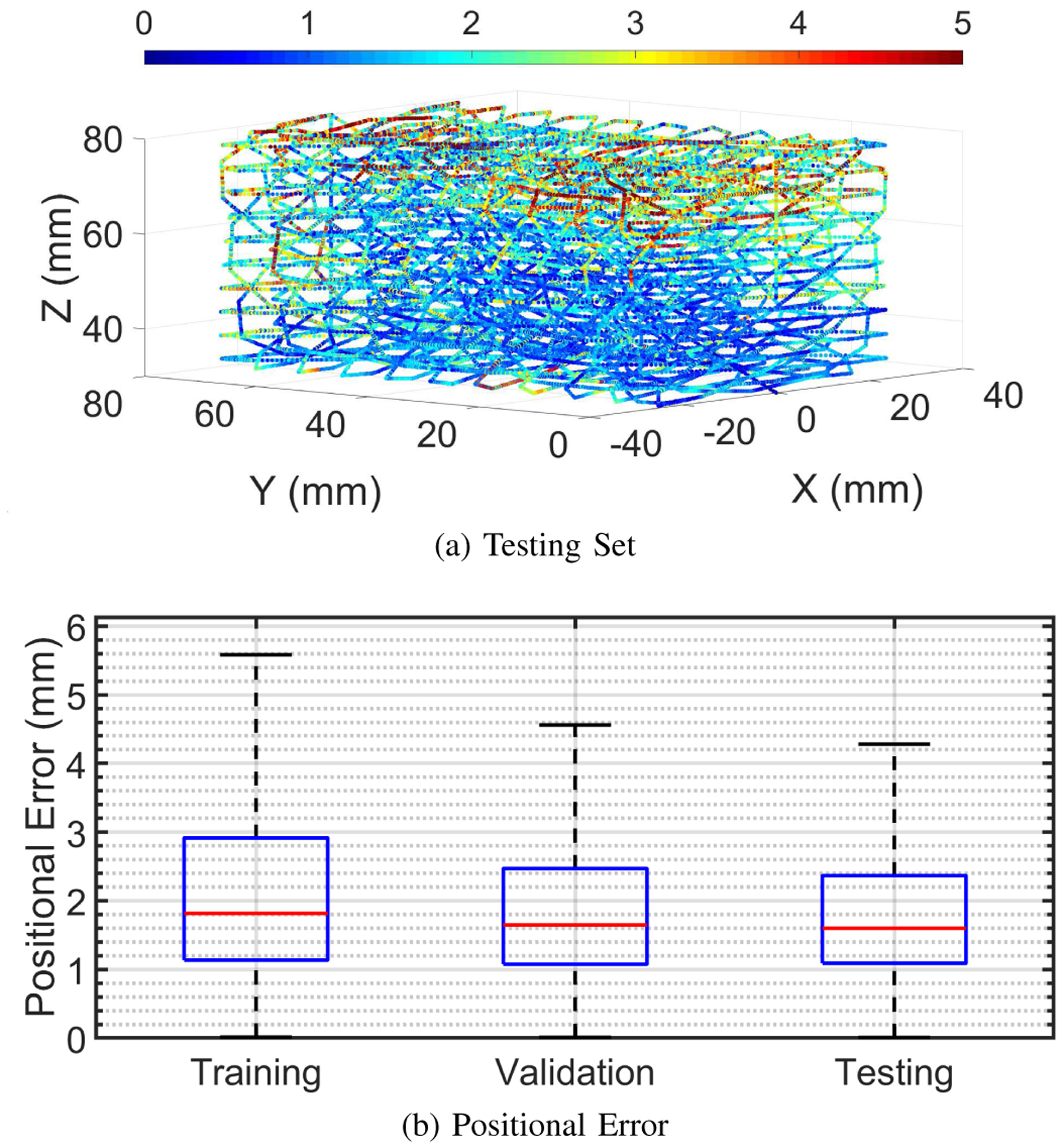
Positional errors of the model trained with compensated rotation shown (a) as a heat map for its testing set, and (b) as a box plot of all errors.
D. Future Considerations
The level of accuracy of our system is satisfactory for many motion tracking applications, including tongue tracking for applications not related to speech such as alternative control for powered wheelchairs [6]. Speech-related applications might require a higher degree of tracking accuracy than our current system can reach with [9] reporting that an accuracy of 0.5 mm is considered acceptable for speech. The latest EMA model (AG501, Carstens Medizinelektronik GmbH, Bovenden, Germany) has a reported positional tracking accuracy of 0.3 mm (RMSE) at the best location in the magnetic field [25]. To be noted, the evaluation methods for the tracking accuracy of EMA such as in [7]–[9], [25] are significantly different and we believe that ours is more comprehensive since it samples an entire volume with both translational and rotational motion. Also, EMA relies on a technology that is likely superior for tracking but is not amenable to a wearable form factor. Therefore, it is quite challenging for our system to reach a similar tracking accuracy as EMA at this stage, though future studies will be conducted to improve it since it is likely that a higher accuracy can be obtained.
V. Conclusion
This work presented an evaluation of the tracking accuracy of a novel motion tracking system that was designed to overcome the shortcomings of the traditional permanent magnet localization. Rather than tracking a permanent magnet with numerous magnetometers fixated around the working volume, an IMU is used as the tracer and tracked inside a local magnetic field generated by a magnet strip. This allows the system to not only be wearable but also more practical for tongue tracking applications since the magnet strip can be hidden from view by being placed further from the user’s face. The tracer is designed to be as unobtrusive as possible with a current size of 6×6×0.8 mm3, and with the potential to be further reduced. Our novel tracking method builds upon our previous work by using the IMU’s magnetometer to measure the varying magnetic field over its position. These magnetic measurements are then compensated for the tracer’s orientation and fed into a magnetic localization algorithm. The positional errors evaluated in a volume of 8×8×5 cm3, with the tracer being rotated ±50° about its pitch and roll, resulted in median and Q3 values of 1.6 mm and 2.4 mm, respectively.
These reported results in tracking accuracy can be further increased by implementing some improvements to our system. For instance, the magnet strip can be redesigned to increase the strength of the local magnetic field in our working volume. The orientation compensation can be improved with a better calibration of the IMU and the implementation of a more advanced sensor fusion algorithm. The magnetic localization can be more accurate by using a more complex architecture for its neural network and a more optimal pre-processing of the samples.
This proposed system offers a new alternative to existing motion tracking systems, especially as a practical, affordable, and wearable tongue tracking system to be used in various application such as the front-end for a silent speech interface, a treatment tool in speech therapy, and an alternative control paradigm for people with quadriplegia.
Acknowledgments
This work was supported by the National Institute on Deafness and Other Communication Disorders under Grant 5R01DC016621.
REFERENCES
- [1].Katz WF and McNeil MR, “Studies of articulatory feedback treatment for apraxia of speech based on electromagnetic articulography,” Perspectives on Neurophysiology and Neurogenic Speech and Language Disorders, vol. 20, no. 3, pp. 73–80, 2010. [Google Scholar]
- [2].Katz W, Campbell TF, Wang J, Farrar E, Eubanks JC, Balasubramanian A, Prabhakaran B, and Rennaker R, “Opti-speech: A real-time, 3d visual feedback system for speech training,” in Proc. Interspeech, 2014, pp. 1174–1178. [Google Scholar]
- [3].Kim M, Cao B, Mau T, and Wang J, “Speaker-independent silent speech recognition from flesh-point articulatory movements using an lstm neural network,” IEEE/ACM Transactions on Audio, Speech, and Language Processing, vol. 25, no. 12, pp. 2323–2336, 2017. [DOI] [PMC free article] [PubMed] [Google Scholar]
- [4].Denby B, Schultz T, Honda K, Hueber T, Gilbert JM, and Brumberg JS, “Silent speech interfaces,” Speech Communication, vol. 52, no. 4, pp. 270–287, 2010. [Google Scholar]
- [5].Schultz T, Wand M, Hueber T, Krusienski DJ, Herff C, and Brumberg JS, “Biosignal-based spoken communication: A survey,” IEEE/ACM Transactions on Audio, Speech, and Language Processing, vol. 25, no. 12, pp. 2257–2271, 2017. [Google Scholar]
- [6].Sahadat MN, Sebkhi N, Anderson D, and Ghovanloo M, “Optimization of tongue gesture processing algorithm for standalone multimodal tongue drive system,” vol. 19, no. 7, pp. 2704–2712, 2019. [Google Scholar]
- [7].Yunusova Y, Green JR, and Mefferd A, “Accuracy assessment for ag500, electromagnetic articulograph,” Journal of Speech, Language, and Hearing Research, vol. 52, no. 2, pp. 547–555, 2009. [DOI] [PMC free article] [PubMed] [Google Scholar]
- [8].Berry JJ, “Accuracy of the ndi wave speech research system,” Journal of Speech, Language & Hearing Research, vol. 54, no. 5, pp. 1295–1301, 2011. [DOI] [PubMed] [Google Scholar]
- [9].Savariaux C, Badin P, Samson A, and Gerber S, “A comparative study of the precision of carstens and northern digital instruments electromagnetic articulographs,” Journal of Speech, Language, and Hearing Research, vol. 60, no. 2, pp. 322–340, 2017. [DOI] [PubMed] [Google Scholar]
- [10].Wang J, Samal A, Rong P, and Green JR, “An optimal set of flesh points on tongue and lips for speech-movement classification,” Journal of Speech, Language, and Hearing Research, vol. 59, no. 1, pp. 15–26, February 2016. [DOI] [PMC free article] [PubMed] [Google Scholar]
- [11].Kelly S, Main A, Manley G, and McLean C, “Electropalatography and the linguagraph system,” Medical Engineering & Physics, vol. 22, no. 1, pp. 47–58, 2000. [DOI] [PubMed] [Google Scholar]
- [12].Gibbon F and Lee A, “Electropalatography for older children and adults with residual speech errors,” Semin Speech Lang, vol. 36, no. 04, pp. 271–282, 2015. [DOI] [PubMed] [Google Scholar]
- [13].Mnard L, Aubin J, Thibeault M, and Richard G, “Measuring tongue shapes and positions with ultrasound imaging: A validation experiment using an articulatory model,” Folia Phoniatrica et Logopaedica, vol. 64, no. 2, pp. 64–72, 2012. [DOI] [PubMed] [Google Scholar]
- [14].Grimaldi M, Gili Fivela B, Sigona F, Tavella M, Fitzpatrick P, Craighero L, Fadiga L, Sandini G, and Metta G, “New technologies for simultaneous acquisition of speech articulatory data: 3d articulograph, ultrasound and electroglottograph,” Proceedings of LangTech, pp. 1–5, 2008. [Google Scholar]
- [15].Hu C, Li M, Song S, Zhang R, and Meng MQ-H, “A cubic 3-axis magnetic sensor array for wirelessly tracking magnet position and orientation,” vol. 10, no. 5, pp. 903–913, 2010. [Google Scholar]
- [16].Song S, Li B, Qiao W, Hu C, Ren H, Yu H, Zhang Q, Meng MQ-H, and Xu G, “6-d magnetic localization and orientation method for an annular magnet based on a closed-form analytical model,” vol. 50, no. 9, pp. 1–11, 2014. [Google Scholar]
- [17].Foong S and Sun Z, “High accuracy passive magnetic field-based localization for feedback control using principal component analysis,” MDPI Sensors, vol. 16, no. 8, p. 1280, 2016. [DOI] [PMC free article] [PubMed] [Google Scholar]
- [18].Sebkhi N, Desai D, Islam M, Lu J, Wilson K, and Ghovanloo M, “Multimodal speech capture system for speech rehabilitation and learning,” vol. 64, no. 11, pp. 2639–2649, 2017. [DOI] [PMC free article] [PubMed] [Google Scholar]
- [19].Sebkhi N, Sahadat N, Hersek S, Bhavsar A, Siahpoushan S, Ghoovanloo M, and Inan OT, “A deep neural network-based permanent magnet localization for tongue tracking,” vol. 19, no. 20, pp. 9324–9331, 2019. [Google Scholar]
- [20].Lv C, Chen X, Huang H, and Zhou Z, “Study on calibration method for tri-axial accelerometers,” in 2015 IEEE Metrology for Aerospace (MetroAeroSpace), June 2015, pp. 15–20. [Google Scholar]
- [21].Cui X, Li Y, Wang Q, Zhang M, and Li J, “Three-axis magnetometer calibration based on optimal ellipsoidal fitting under constraint condition for pedestrian positioning system using foot-mounted inertial sensor/magnetometer,” in 2018 IEEE/ION Position, Location and Navigation Symposium (PLANS), April 2018, pp. 166–174. [Google Scholar]
- [22].Livermore P, Finlay C, and Bayliff M, “Recent north magnetic pole acceleration towards siberia caused by flux lobe elongation,” Nature Geoscience, vol. 13, no. 5, p. 387391, May 2020. [Google Scholar]
- [23].Rudy K and Yunusova Y, “The effect of anatomic factors on tongue position variability during consonants,” Journal of Speech, Language, and Hearing Research, vol. 56, no. 1, pp. 137–149, February 2013. [DOI] [PubMed] [Google Scholar]
- [24].Yunusova Y, Rosenthal JS, Rudy K, Baljko M, and Daskalogiannakis J, “Positional targets for lingual consonants defined using electromagnetic articulography,” Journal of the Acoustical Society of America, vol. 132, no. 2, pp. 1027–1038, 2012. [DOI] [PubMed] [Google Scholar]
- [25].Sigona F, Stella M, Stella A, Bernardini P, Gili Fivela B, and Grimaldi M, “Assessing the position tracking reliability of carstens’ ag500 and ag501 electromagnetic articulographs during constrained movements and speech tasks,” Speech Communication, vol. 104, pp. 1–35, 2018. [Google Scholar]


