Abstract
A Time-Delay Integration (TDI) image processing system has been developed to capture ICON’s Far Ultraviolet (FUV) Spectrographic Imager data. The TDI system is designed to provide variable-range motion-compensated imaging of Earth’s nightside ionospheric limb and sub-limb scenes viewed from Low Earth Orbit in the 135.6 nm emission of oxygen with an integration time of 12 seconds. As a pre-requisite of the motion compensation the TDI system is also designed to provide corrections for optical distortions generated by the FUV Imager’s optical assembly. On the dayside the TDI system is used to process 135.6 nm and 157.0 nm wavelength altitude profiles simultaneously. We present the TDI system’s design methodology and implementation as an FPGA module with an emphasis on minimization of on-board data throughput and telemetry. We also present the methods and results of testing the TDI system in simulation and with Engineering Ground Support Equipment (EGSE) to validate its performance.
Keywords: Far Ultraviolet, Instrumentation, Ionosphere, CCD Imaging, TDI, FPGA
1. Introduction
Achieving spatially-resolved imaging of a scene undergoing relative motion is a challenge common to both satellite- and ground-based imaging. Various schemes have historically been developed to compensate for the effects of the motion blur caused by relative motion between imager and target scene. These schemes often employ a physical mechanism by which motion is tracked, or utilize custom-designed digital imaging sensors which co-add incoming image frames in such a way as to counteract the motion offset since the start of integration. The digital variety of heritage TDI sensors have primarily been limited to one-dimensional line scan configurations, and or scenes which drift at a constant rate and direction. Heritage instruments utilizing this approach include the IMAGE FUV instrument [Mende et al., 2000] on which much of the ICON FUV TDI system was based.
The TDI system on IMAGE FUV was employed primarily to compensate for the rotation of the spacecraft while viewing the earth from a large distance and as such it needed only to compensate for the apparent image motion at a fixed distance. ICON FUV scenes of interest are not at constant range across the field of view, which gives rise to variations across the image in the observed image motion due to satellite travel. In particular, the drift rate of the image at a pixel is inversely proportional to the distance from the emission source to the ICON satellite. This implies that pixels whose emission source points are further away will move more slowly across the FUV detector than those at closer range. In order to handle this non-uniformity in the observed scene geometry and motion it was necessary to develop additional functionality to expand on the heritage digital TDI techniques.
The ICON FUV instrument has two imaging channels corresponding to two FUV wavelength bands for the sunlit atmosphere daytime observations. These channels are nominally centered at 135.6 nm and 157.0 nm and are referred to as the shortwave (SW) and longwave (LW) channels, respectively. Each channel utilizes an FUV image converter/intensifier combination coupled with a CCD detector. The imaging channels share a common optic axis pointed downward 20° from local horizontal viewing in the northward direction from a circular orbit at a nominal altitude of 575 km.
When viewed from Low Earth Orbit, the limb intensity altitude profiles of selected FUV spectral features in the daylight sunlit conditions can be used to determine respective species densities and temperatures [Meier et al., 2008; Meier, 1991]. One of the primary goals of ICON FUV is to produce these limb intensity altitude profiles, which require only one-dimensional vertical imaging of the emissions. Since the satellite motion is in the horizontal dimension approximately along lines of constant tangent height, it is relatively unimportant to compensate for image smearing caused by satellite motion in forming limb intensity altitude profiles.
At night when the atmosphere is not sunlit, the FUV instrument is required to make two-dimensional images of the nightglow emissions of atomic oxygen in the 135.6 nm channel. Because the spacecraft is moving horizontally in the camera frame of reference, spacecraft motion causes image blurring which adversely affects horizontal imaging resolution. In an ideal system it would be possible to take rapid images and downlink the data and perform all necessary image processing (e.g. blur removal) on the ground. Unfortunately ICON’s downlink data rates do not support this type of operation. This necessitates on-board data processing including co-adding of consecutive image frames thereby reducing the downlink data volume while increasing the imaging signal-to-noise ratio. To enable on-board processing of two-dimensional image data, the ICON FUV cameras are read out at an exposure rate of one frame every 120 ms with a nominal integration time of 12 seconds. Integrating many short back-to-back camera images in lieu of a single 12-second CCD exposure provides the capability to correct the blur caused by real-time spacecraft motion while simultaneously increasing FUV imaging SNR (see the companion FUV instrument paper).
During ICON’s requirement development it was determined that the FUV instrument must provide the capability to resolve ionospheric features as small as 16 km in horizontal spatial extent on the nightside, corresponding to the expected features of equatorial plasma structures. The 12-second integration time coupled with ICON’s orbital motion of 7.6 km/s causes a non-negligible 91.2 km motion blur in the image integration process. It is therefore necessary to compensate for spacecraft motion using TDI processing during each 12-second integration period in order to satisfy the spatial resolution requirements for FUV imaging.
To be able to calculate the motion of the various regions in the image, the distance from the emitting region to the spacecraft is needed. To obtain the range we assume models for the geometry of the emitting regions. Assuming that the peak emission occurs at 300 km in the nighttime ionosphere, we expect to observe the phenomena from above from ICON’s 575 km altitude, with elevations below the spacecraft corresponding to the tangent height of 300 km. These observations are referred to as “sub-limb view” observations. Emissions that are produced at elevation angles higher than the angle corresponding to the 300 km tangent height can also be observered, and these are referred to as “limb view” observations.
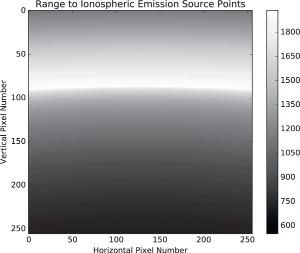
In our model the ICON FUV instrument FOV covers the ionospheric scene whose range extends from 550 km to 1950 km from the ICON observatory (Fig. 1). Because of the range-to-target variance, pixels in the image plane do not drift uniformly across the detector as the spacecraft moves in its orbit. Consequently it is not possible to employ a simple linear motion compensation scheme to compensate for image blurring caused by ICON’s satellite motion.
Fig. 1.
Nightside ionospheric emission surface range in km from the ICON FUV Imager corresponding to the predicted geometry of ICON’s nominal orbit position and pointing. The top portion of the image is the so-called limb emission surface. Below it is the so-called sub-limb emission surface. The boundary between limb and sub-limb is marked by the contour of furthest distance (lightest color) at vertical pixel 90. An effective sub-limb layer at 300 km tangent altitude is assumed in the scene geometry calculations.
A novel digital TDI image processing algorithm was developed to remove the motion blur caused by the satellite motion in a varying range-to-target FUV scene. The algorithm performs configurable discrete image transformations the on incoming camera frames in such a way that the images are projected onto a surface that has uniform linear motion in the transformed frame of reference. The resulting linear motion is then corrected for by applying an image displacement offset corresponding to the net motion in the transformed-image space since the start of image integration.
The particular image transformation required to linearize pixel motion depends on both the observed FUV scene’s geometry and its desired post-transform spatial resolution. This is because the apparent motion of the various regions in the image depends on the distance from the emitting region to the spacecraft. It is therefore necessary to obtain the distances from the emission surface to the ICON spacecraft.
We expect that the TDI co-added imaging will only be used on the nightside to observe horizontal ionospheric structuring. In a model of the nightside emissions we assume that the nighttime ionosphere has its brightest emission at 300 km corresponding to the bottom side of the F-region where ion-electron recombination might be peaking. The 300 km tangent height surface is referred to as the sub-limb surface. At view elevations above the 300 km limb tangent point we assume that the maximum intensity of the glow will be at their respective limb tangent points, referred to as the limb surface.
The natural choice of transformation corresponding to both the nightside limb-sublimb emission geometry and satellite motion is a mapping from the camera frame of reference into a spherical system aligned with the instantaneous orbit axis, referred to as Spacecraft Orbit-Aligned Position (SOAP) coordinates. SOAP coordinates centered on Earth, where the x-direction passes through the spacecraft position at the start time of the integration, the y-direction is the spacecraft velocity direction at the start time of the integration, and the z-direction is in the local vertical completing the right-handed system. Latitudes and longitudes are computed by using a spherical system with the satellite orbit plane as the equator recognizing that x and y are in the orbit plane.
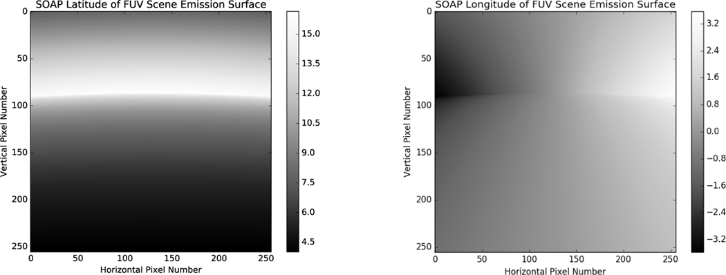
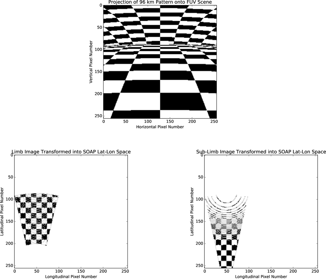
In the SOAP coordinate system the spacecraft starts each integration at 0 degrees latitude and longitude with an orbit radius corresponding to geocentric distance. The expected nightside emission surface in these coordinates is shown in Fig. 2. Because the orbit is circular, the ICON observatory moves at a nearly constant rate in the orbit-aligned longitudinal direction as the integration over time is performed. This implies that image motion blur can be corrected for with an accumulating linear offset incremented for each incoming camera frame by an amount corresponding to the spacecraft’s longitudinal displacement per frame. Fig. 3 illustrates the transformation from the camera frame into limb and sub-limb images in SOAP lat-lon space.
Fig. 2.
Spacecraft Orbit-Aligned Position (SOAP) coordinate latitude (left) and longitude (right) in degrees of the modeled nightside emission surface that ICON FUV will image. The spacecraft moves in approximately linear motion in the longitudinal direction in this space.
Fig. 3.
A square-wave pattern of spatial extent 96 km/square is projected onto a simulated ionospheric emission surface that ICON FUV will image (top). The portions of the projected square-wave image in the camera frame of reference corresponding to the limb and sub-limb are then transformed (bottom-left and bottom-right, respectively) into the Spacecraft Orbit-Aligned Position (SOAP) latitude-longitude coordinate space of size 8×8 km2 pixels in the longitudinal and latitudinal directions. In SOAP lat-lon space pixels subtend constant longitudinal and latitudinal extent, and the curvature of the scene is observed to vanish as the surface is flattened by the transformation. Pixel distributions resembling Moire patterns of fixed-pattern noise are alsó observed as a result of the image transformation process.
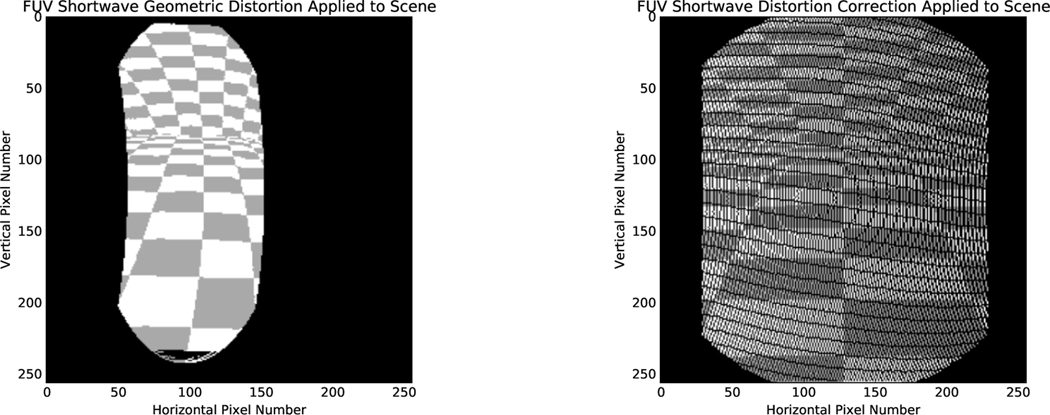
In addition to motion blur, there are several intra-instrument effects which adversely affect imaging performance. One such artifact is due to the compact optical design of the FUV instrument which introduced a permanent geometric optical distortion whose effect is primarily to compress incoming images in the horizontal imaging dimension (Fig. 4). The image transformations applied as part of the TDI process are computed in undistorted coordinates, so it was necessary to devise a scheme to remove this distortion prior to performing the conversion to spacecraft latitude-longitude coordinates. The geometric distortion correction is achieved by applying an additional image transformation to incoming camera frames which applies the inverse of the geometric distortion’s optical transfer function. The geometric distortion’s optical transfer function was determined as part of the FUV instrument calibration campaign prior to launch.
Fig. 4.
ICON FUV shortwave geometric optical distortion applied to a simulated FUV scene image (left). The effect of the distortion is to compress FUV shortwave images horizontally into a banana-like shape. The distortion is corrected for using a discrete inverse transformation to the distortion (shown applied on right). As in Fig. 3, pixel Moire patterning is observed.
Simulated modeling of the FUV instrument’s optics revealed that temperature changes can temporarily deform the FUV instrument in such a way as to produce an undesirable linear shift in the pixel positions of images arriving at the CCD. It is therefore necessary to both track the temperature-induced offset and compensate for it. This is achieved by exploiting the fact that the FUV optics produce a sharp bright-to-dark edge at the boundary of the spectral grating in each image which can be tracked to determine whether a pixel position offset is present. Correction for this image shift is achieved by ground commands to enable appropriate inverse pixel translation in FUV TDI processing.
ICON FUV has a scanning mirror that allows the instrument to steer its pointing direction by up to ±30° by functioning as a periscope. The periscope configuration of the scan mirror results in an in-plane rotation of FUV images by an amount proportional to the scanning mirror rotation angle. FUV TDI processing operates in a true SOAP coordinate system and therefore it is necessary to counteract this rotation to satisfy the pixel position-dependence of the TDI processing. This rotation correction is achieved by applying a rotation image transformation corresponding to the inverse of the turret rotation.
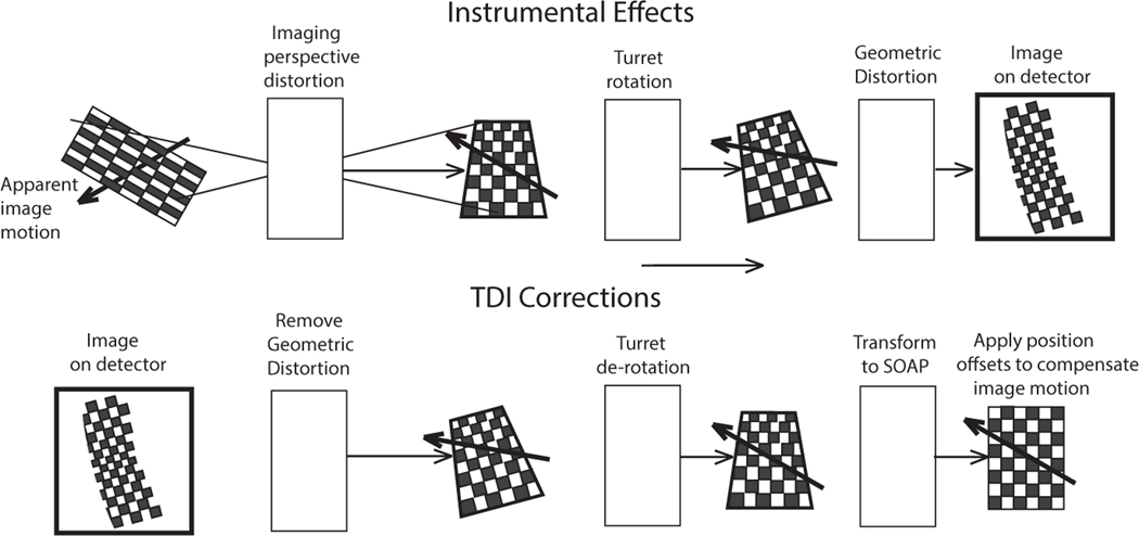
Fig. 5 summarizes the artifacts introduced by the instrument and the corresponding corrections performed in on-board processing. The original scene on the left is imaged by the imager producing a perspective distortion because of the oblique viewing of a spherical surface. The apparent motion of the image due to the orbital motion of the satellite is illustrated with an arrow. If the turret is not at its mid position then the entire image will be rotated by the turret angle. Finally the image will be distorted by geometric distortion of the imager optics.
Fig. 5.
Instrumental effects which affect FUV TDI imaging. The top row shows the artifacts introduced by the instrument which is viewing a pattern in three dimensions and produces an image with perspective distortion. The bottom row shows the successive corrections that need to be applied by the on-board TDI image processing.
In order to successfully TDI and compensate for the satellite motion all of these distortions need to be removed. In the bottom row of Fig. 5 starting with the distorted image first, the image must be rotated to remove the tilt due to the turret rotation angle. The last step is to transform the image into SOAP latitude-longitude coordinates thus removing the perspective distortion (i.e. range-dependence) by representing the image in a spherical coordinate frame where the pixels move uniformly in latitude and longitude as prescribed by the angle at which the satellite is traveling along its orbit. By taking the images in this frame of reference it is possible to co-add the images while suitably displacing them so that the satellite motion is compensated for.
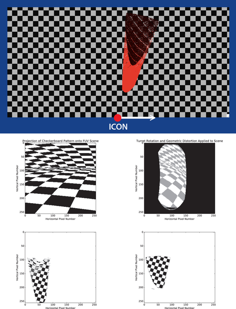
For a complete simulation of the TDI processing we produced a checker board pattern which is superposed on a spherical modeled atmosphere to show a regular and recognizable pattern. This pattern is aligned with the satellite’s orbital track (Fig. 6) and represented in the SOAP coordinate system. The vertical dimension on the page is equivalent to 2000 km distance perpendicular to the orbit track. The great circle distance along the 300 km altitude is 1884 km and the size of the region is adequate to image regions at 300 km and above. The imager is shown to look with a turret angle of 15° forward. Projections of the limb and sub-limb views are shown on the figure as black and red regions, respectively. The basic principle of the spacecraft motion compensation is that if the image is projected onto the sphere representing the 300 km altitude region then a constant motion on the figure will eventually compensate the motion of all pixels.
Fig. 6.
Simulated TDI processing with a turret angle of 15 degrees forward from the spacecraft −y-axis. Top: ICON is shown viewing checker board pattern in SOAP latitude-longitude space. Middle-left: FUV scene as it would appear in the camera frame of reference with only perspective distortion (no instrumental effects) and a square field of view viewed at a 15 degree turret angle. Middle-right: Typical image observed by the FUV shortwave CCD of the left image containing the typical instrumental effects of geometric distortion and turret rotation. Bottom: 12-second 100 frame TDI co-addition with motion compensation, distortion removal, and ground flat-fielding to produce a spatially resolved sub-limb (left) and limb view (right), respectively. The gaps seen at the top of the sub-limb image are a result of the scene geometry transformation (there is no data for these pixels in source images).
The first part of the TDI simulation is the generation of a raw image on the imager focal plane. In the actual data taking this is accomplished by the limb viewing observing geometry and by the instrument itself. In our simulation however we had to generate code to make an image sequence that simulated the moving image of the checker board. The geometry produced by the code was used to generate a lookup table (LUT; see the implementation section) in which the addresses of output pixels provided the horizontal and vertical pixel number for the corresponding transformed input pixel number is contained. This allowed the transformation of the images in a rapid manner. A typical image is shown on the middle-right of Fig. 6. This image is one of a sequence of moving images showing both the limb and sub-limb views, respectively. It should be noted that the images were constructed simply by fetching the intensities based on the LUT. We generated a sequence of 100 such frames and for each frame included a displacement due to the satellite motion at 7.6 km/s viewed at the 15 degree turret angle. A movie of the 100 frames (not shown) demonstrated that the checks were moving from right to left with a small vertical motion component at a 15 degree angle as expected.
The next step of the simulation was to generate the reverse LUT which uses the image generated in the previous procedure and transforms it back to the plane which is being imaged containing the checker board pattern. The last step of the simulation was to co-add the 100 images while applying this reverse LUT and adding a fixed backward step to compensate for the satellite motion prior to co-adding the images. This LUT-based processing is consistent with the on-board FUV TDI processing. The resultant sub-limb and limb images are also shown in Fig. 6 at the bottom-middle and bottom-right.
The simulation shows that it is possible to retrieve sptially-resolved images by this technique while simultaneously increasing imaging signal-to-noise by virtue of the co-adding process. We anticipate the technique will be highly useful for imaging the ionospheric equatorial bubbles. We also expect that consecutive images of the type shown in Fig. 6 can be used to generate a continuous pattern of the ionosphere in the region covered by the ICON FUV Imager.
2. Raw Instrument Products
The ICON FUV TDI system produces all of the FUV instrument data that is packaged into level-zero science data products by ICON’s flight software. The first of these is the FUV Limb Altitude Profiles product, which is formed by subdividing the FUV instrument’s horizontal field of view into six horizontal bins. Within each bin pixels in the same row are summed to a single value to provide an altitude profile of the observed FUV radiances at the tangent height corresponding to the bin. Limb Altitude Profiles are produced on both the dayside and nightside.
The second type of data which are packaged as a level-zero product produced by the TDI system are Map Images. These images nominally contain a spatially-resolved view of the ionospheric limb or sub-limb scenes. The images are formed by first applying instrument distortion corrections and the scene-to-SOAP latitude-longitude space transformation to incoming camera frames, and then co-adding the transformed images into an output image while displacing each image to correct for spacecraft motion. This is equivalent to summing the images at positions corresponding to the net spacecraft motion since the start of the integration in SOAP lat-lon coordinates. Map Images are only produced on the nightside.
The third type of precursor level-zero data product produced by the TDI system are Thermal Calibration Coupons. These coupon images are formed by extracting a small (nominally 25×10 pixel) sub-region of incoming FUV images and co-adding them without additional processing. These data are taken at the bottom edge of the field of view where the physical edge of the grating can typically be seen for the purpose of tracking the position of the FUV Imager’s diffraction grating edge. Tracking the edge allows thermally-induced optical shifts to be tracked and corrected for.
3. System Implementation
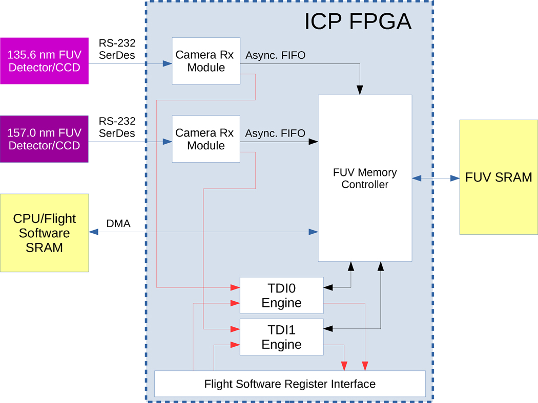
The choice was made to implement the FUV TDI system as a real-time algorithm in ICON’s payload FPGA. This decision followed a data throughput analysis which showed that a dedicated digital data processing sub-system would be required to perform FUV imaging (Fig. 7). The ICON FUV TDI system is implemented within this FUV digital data sub-system and is responsible to perform all of the real-time FUV image data processing. The type of image processing performed by the TDI system depends on the instrument’s science operating mode (dayside vs. nightside). In dayside mode the 135.6 nm shortwave channel and the 157.0 nm longwave channel both are both processed to produce Limb Altitude Profiles products. In nightside mode the 135.6 nm channel is processed solely to create both Map Images and Limb Altitude Profiles products.
Fig. 7.
High-level view of the ICON FUV digital data acquisition and processing sub-system. The relationships between the TDI engines and other sub-system components are shown. Black and blue arrows represent digital data paths in the directions of the arrows, where blue wires represent data paths crossing I/O boundaries. Red arrows indicate control signals and status flags. Asynchronous First-In First-Out (FIFO) buffering is used to transfer data from the CCD readout electronics to ICON’s payload Instrument Control Package (ICP) FPGA. A priority-based memory controller arbitrates access to FUV memory. Direct memory access (DMA) is used to transfer processed images and LUTs from FUV memory to flight software CPU memory and vice versa. FUV memory is used to store incoming FUV camera frames, TDI integration buffers, and active operational LUTs. Flight software requests DMA transfer of processed TDI image buffers where completion of TDI processing is indicated by the TDI engines through the register interface.
The FUV CCD cameras output images are produced in a continuous frame-transfer video stream at a nominal rate of 120 ms exposures per frame over a Serializer-Deserializer (SerDes) link to ICON’s payload FPGA. Each image is binned down 2-by-2 on the CCD from its native resolution of 1072×1030 pixels down to 536×515 pixels prior to transmission to the ICON payload FPGA. The CCD readout ADC electronics provide 14-bits of resolution per pixel.
Upon receipt of a CCD camera frame, a camera receiver module in the ICON payload FPGA performs region of interest (ROI) cropping to remove unwanted edge portions of the input images in order to minimize data volume. The camera receiver modules also perform a secondary 2-by-2 digital binning on the received images. The binning and cropping are combined to produce TDI input images which are 256×256 pixels in size. The camera receiver modules are also responsible to provide signals to instruct the TDI modules to begin processing the frame.
The FUV TDI system is composed of two TDI processing modules, referred to as TDI0 and TDI1 respectively, which process the images produced by the FUV CCD electronics frame-by-frame. Upon receiving each new frame the TDI module immediately processes the incoming image by applying a transformation to it by modifying each pixel address using a LUT, and then co-adds the transformed camera frame into an integration buffer in memory. In all of the TDI science operating modes, each TDI module outputs two processed images which come from a single source channel. The reason for outputting two images per module is to provide the capability to perform alternative types of real-time processing with the same set of source images.
FUV TDI processing makes extensive use of image transformations which are encoded as a discrete mapping between input and output pixel locations. This discrete mapping is stored in a binary image known as a lookup table (LUT). ICON’s flight software does not have the capability to compute the science LUTs on-board and they are thus pre-computed before launch and stored in non-volatile magnetic memory. LUTs may also be uploaded from the ground post-launch as needed.
Lookup tables can encode a variety of different types of image transformations, including 1) mappings of emission points on the ionospheric limb and sub-limb scenes from camera space to SOAP lat-lon (range-adjusted) coordinates, 2) image rotations in the image plane to counteract the periscopic rotation introduced by the FUV instrument’s scanning turret mirror, 3) geometric optical distortion corrections to apply the inverse of the distortion, 4) horizontal binning of input images to create altitude profiles of ionospheric radiances, and 5) thermal calibration coupon sub-regioning. Table 1 summarizes these LUTs.
Table 1.
Summary of lookup table types used by ICON FUV TDI processing.
| Lookup Table Type | Description | Calculation Method |
|---|---|---|
| Geometric Distortion Correction | Counteracts FUV SW and LW distortion | Make inverse of geometric distortion data determined in calibration |
| Rotation | Applies a discrete-valued image rotation by a specific angle about a specific pixel | Discretize a 2D rotation matrix |
| Thermal Coupon | Extracts a sub-region of an image for on-orbit thermal offset calibration | Determine the desired windowing boundaries |
| Limb Altitude Profiles | Performs horizontal binning on images to form intensity profiles | Choose bin widths to provide sufficient SNR of expected scene |
| Limb/Sub-Limb Map Images | Transforms camera images into SOAP latitude-longitude space in order to create temporally- and spatially-resolved maps of ionospheric radiances | Perform ray-tracing based on predicted spacecraft altitude and pointing to determine expected scene geometry and its transformation from the camera view to SOAP lat-lon coordinates. The worst-case expected ICON 3-sigma orbit gives rise to the need for multiple scene geometry calculations corresponding to 25 km altitude steps. Each LUT is valid within ±12.5 km of the assumed altitude in order to meet FUV spatial resolution requirements |
Image processing with lookup tables provides a significant performance advantage in terms of the number of computations required to produce processed FUV science data. This is due to the ability of LUTs to allow computationally expensive scene geometry calculations to be computed on the ground and stored permanently in the LUTs. In addition, the discrete-valued nature of LUTs further reduces computational complexity by reducing the TDI image transformation process to a simple memory indexing operation based on the values in the LUT.
The on-board TDI FPGA processing is achieved by applying a LUT image transformation mapping to incoming CCD images I[x,y] to produce a transformed-version of the image denoted by I′[u,v], where [x,y] are the original camera space pixel coordinates and [u,v] are post-transform pixel coordinates (square brackets indicate discrete indexing where only the integral value is used). The transformation from I to I′ is chosen depending on the desired data product to be produced and the instrumental effects to be removed. The generalized LUT image transformation is equivalent to the matrix multiplication I′vec = ΛIvec, where I′vec and Ivec are vectorized versions of I and I′ formed by converting two-dimensional 256×256 pixel images into one-dimensional 65536 element vectors, and Λ is the LUT transform matrix of size 65536×65536. The LUT transform matrix Λij is 1 if the vectorized pixel i in the input image maps to the vectorized output pixel j, otherwise it is 0.
Because of the exceptionally large size of the LUT matrix, the matrix multiplication is performed in a specialized way. The LUT transformation matrices Λ contain exactly 65536 (256×256) non-zero entries corresponding to the 65536 pixels in the incoming FUV CCD images. The sparseness of these matrices is exploited to reduce the complexity needed to perform the matrix multiplication. Instead of directly performing the multiplication, a condensed lookup table of size 256×256 is used which contains the mapping from cropped/binned camera image pixels [x,y] to transformed output destination pixels [u,v]. The TDI modules loop over this condensed table and map every incoming CCD image pixel to its output destination. This loop is equivalent to processing only the non-zero entries of the LUT matrix for a total of k = 256×256 pixel co-additions. This significantly reduces the matrix multiplication computational complexity from (k2) on-board memory read-modify-write operations to (k) on-board memory read-modify-write operations, where signifies Big O notation.
In practice it is necessary to apply several transformations to incoming FUV images in order to simultaneously compensate for perspective projection, image rotation, and geometric distortion, as well as to form the desired science data product from the distortion-corrected image. To achieve this, ICON’s Flight Software builds an Operational Lookup Table (Operational LUT) by combining three pre-loaded LUTs in series. The series lookup table combination is equivalent to matrix multiplying the three LUT transformation matrices, with the Operational LUT matrix being given by Λ:
| (1) |
where Λi for i ∈ {1,2,3} are lookup table transformation matrices with Λ1 nominally serving as the geometric distortion correction, Λ2 nominally serving as the turret rotation correction, and Λ3 nominally serving as a science transformation (Map Image or Limb Altitude Profiles) or a thermal calibration coupon. The Operational LUT is formed using the same loop that was used to perform the sparse matrix mapping operations described above.
After applying a lookup table transformation to incoming images, the transformed images are co-added into a 32 bit/pixel TDI output image buffer O[u,v]. The output image buffers are double-buffered to allow for flight software retrieval of a completed integration while a new integration is simultaneously performed on new incoming images. Each output buffer is cleared by FSW upon receipt of the image.
In addition to LUT processing, it is necessary to also perform motion compensation on the transformed images. In the specific case of the nightside image processing, each transformed camera frame is co-added into a 256×512 TDI integration image buffer O[u,v] (a 256×256 buffer for each of the limb and sub-limb images, respectively) at an offset position in the buffer of [u+U,v+V], where u and v are indices corresponding to particular SOAP latitudes and longitudes θ and φ, respectively, andU =∑i Δui andV =∑i Δvi correspond to the displacements of the spacecraft’s SOAP latitude-longitude position relative to the start of the integration for each processed frame up to the current frame i, and Δu and Δv are the longitudinal and latitudinal SOAP offsets per incoming frame. It is assumed that Δv and Δu are constant across each 12-second integration so that real-time ACS knowledge is not required to perform the processing. The u,v image pixel position offsets per frame due to satellite motion are given by:
| (2) |
| (3) |
Where
| (4) |
is the longitudinal displacement per Δt = 120 ms camera frame at the spacecraft velocity vSC at altitude a and turret scanning mirror angle α, and kφ and kθ are configurable LUT-transform conversion factors relating SOAP longitude and latitude to pixel size (post-transform spatial resolution) in the output image. The factors cos α and sin α appear because changes in the scanning turret mirror angle cause the FUV instrument’s view direction to deviate from its nominal direction perpendicular to the spacecraft ram direction (see Fig. 6). The per-pixel offsets Δu and Δv as well as the net offset quantities U andV are computed as signed fixed-point numbers with 8 bits of fractional precision. The floor of these values are used when performing the pixel memory location offsetting as pixels in memory can only be accessed discretely.
The transformation-based processing employed by the TDI system often leaves regions of output images empty, and may also create a fixed pixel distribution pattern similar to a Moiré pattern due to the discrete nature of LUT transforms. In addition, not all of the 256×256 pixels in the output images are used as a result of the transformed scene geometry. Noting these facts, the TDI LUT processing algorithm aids in minimizing the data telemetry data volume of its produced data products by marking only the pixels which have been processed in the buffer. This is achieved by reducing the bit depth of the TDI image output buffer from 32 to 31 and using the top bit as a flag to mark that a pixel has been processed. This generates what is known as an Active Pixel Map (APM) which allows ICON’s flight software to telemeter only the active pixels (including zero-valued pixels) which have been processed by the TDI algorithm.
The TDI Image LUTs are computed on the ground under the assumption of a scene geometry based on constant altitude across each 12-second integration as well as a specific instrument pointing. If an incorrect spacecraft altitude and or pointing are assumed the lookup tables can deviate from the actual scene in a way which violates the 16-km horizontal spatial resolution requirement. Software simulations developed to test the TDI system revealed that the spacecraft altitude must remain within ±12.5 km of the altitude assumed in making the LUT. To resolve this issue, LUTs corresponding to the altitude range of ICON’s worst-case predicted 3-sigma orbit insertion are created at 25 km steps and stored on-board. This preloading of LUTs for all possible altitude bins allows ground operators to command which LUT altitude and pointing bin to use based on the actual orbit post-launch.
4. System Testing
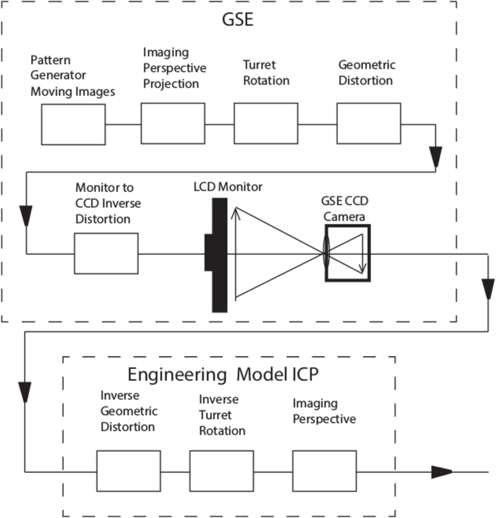
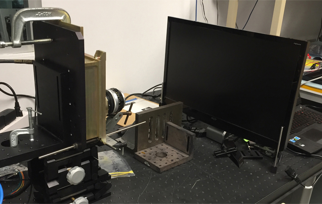
The ICON FUV TDI system was tested by comparing images taken by a laboratory Ground Support Equipment (GSE) version of the TDI system against images produced by software simulations. The TDI software and validation setup is illustrated in Figs. 7 and 8. This system contains an EM ICP and a computer-driven LCD monitor viewed by an EM CCD camera. We used an engineering model of the flight-like CCD cameras that were capable of imaging visible light. The CCD camera had a Nikon lens focused on the LCD monitor which is used to present a simulated image representing the scene geometry that would be observed in the FUV Imager’s field of view suitably distorted by the scene perspective and instrument distortions.
Fig. 8.
Test setup for the ICON FUV TDI hardware and software simulations. A computer generates test patterns to simulate the scene viewed from orbit while moving with satellite velocity. Various modifications are applied to produce images that simulate the images seen by the detectors in the instrument. The CCD output is fed to the flight-like Engineering Model ICP where the flight-like hardware/software processes the images. A photograph of the experimental setup is shown in Fig. 9.
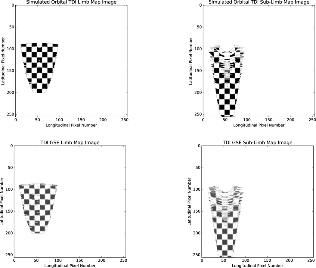
The system performance was tested by commanding the TDI system into its nightside science operating mode and producing a sequence of images moving at simulated spacecraft speeds taking exposures of the simulated orbit scene over the nominal 12-second integration time. As described in Fig. 8 images were generated and the perspective projection and geometric distortions were applied and images were displayed on the LCD monitors. The geometric distortion LUTs were generated during the geometric calibration of the FUV instrument during vacuum chamber testing. Therefore the geometric distortions represented are the actual distortions produced by the actual FUV instrument. The simulations were performed with time-evolving orbit scenes where the spacecraft moves at its nominal rate, at its intended altitude, and pointing of the field of view included. The camera of the TDI GSE system was mounted to an optical bench and pointed toward distorted images on the monitor (Fig. 9). The geometric fidelity of the setup was inspected and found to not introduce geometric distortion, however the coarseness of the experimental mounting assembly did cause up to a pixel worth of pointing error which we chose to ignore. The resident Engineering Model ICP TDI system was then commanded to perform TDI image acquisition and distortion correction on the images displayed on the LCD monitor as though they were real orbit scenes. The resulting images were compared against reference images produced by software simulations in Fig. 10.
Fig. 9.
Photograph of the setup outlined in Fig. 8 used to validate the performance of the EM TDI system. The EM CCD camera and LCD monitor are shown on the left and right, respectively.
Fig. 10.
Simulated orbital 12-second TDI limb (top-left) and sub-limb (top-right) integrations with distortions present, and the same scene processed by the FUV TDI GSE system imaging an LCD monitor displaying the orbit scene with an FUV camera (bottom-left, bottom-right). The images are seen to be similar with slight differences being due to coarseness of the mounting and alignment of the experimental setup.
The GSE-based orbit scene testing reveals that the TDI system performs as expected in its duty to remove FUV instrument distortions and compensate for satellite motion. The images shown in Fig. 10 contain a turret rotation of 0° however tests were performed at other turret rotation angles. In practice it is also necessary to apply a flat-field correction to images processed using the TDI LUT algorithm in order to reduce artificial gain introduced in the process. The LUT flat-fielding is performed in post-processing on the ground.
5. Conclusion and Future Work
The TDI system is a computationally-efficient method of providing Time-Delay Integration to non-linear scene motion as well as imaging distortion removal with ICON’s FUV Imager. The system is robust and able to handle a multitude of imaging artifacts.
Beyond ICON FUV, the TDI processing methodology presented here could be adapted to support future imaging missions. Future work related to the TDI processing will also involve determining image reconstruction techniques based on the LUT processing technique, which have only been minimally investigated at the time of writing.
Acknowledgements
We would like to thank Matthew Dexter, William Rachelson, Carl Dobson, and Irene Rosen for their technical support. We also thank David MacMahon and Stewart Harris for their valuable guidance during the early stages of system development. ICON is supported by NASA’s Explorers Program through contracts NNG12FA45C and NNG12FA42I.
Contributor Information
Colin W. Wilkins, Department of Earth, Planetary, and Space Sciences and Institute of Geophysics and Planetary Physics, University of California, Los Angeles, CA 90095, USA
Stephen B. Mende, Space Sciences Laboratory, University of California, Berkeley, CA 94720, USA
Harald U. Frey, Space Sciences Laboratory, University of California, Berkeley, CA 94720, USA
Scott L. England, Aerospace and Ocean Engineering, Virginia Tech, Blacksburg, VA 24060, USA
References
- 1.Mende S, Heetderks H, Frey H, Lampton M, Geller S, Abiad R, Siegmund O, Tremsin A, Spann J, Dougani H, Fuselier S, Magoncelli A, Bumala M, Murphree S, Trondsen T, Space Science Reviews 91(1/2), 271 (2000). DOI 10.1023/a:1005227915363. URL https://doi.org/10.1023%2Fa%3A1005227915363 [DOI] [Google Scholar]
- 2.Mende S, Heetderks H, Frey H, Stock J, Lampton M, Geller S, Abiad R, Siegmund O, Habraken S, Renotte E, Jamar C, Rochus P, Gerard JC, Sigler R, Lauche H, Space Science Reviews 91(1/2), 287 (2000). DOI 10.1023/a:1005292301251. URL https://doi.org/10.1023%2Fa%3A1005292301251 [DOI] [Google Scholar]
- 3.Meier RR, Picone JM, Drob D, Bishop J, Emmert JT, Lean JL, Stephan AW, Strickland DJ, Christensen AB, Paxton LJ, Morrison D, Kil H, Wolven B, Woods TN, Crowley G, Gibson ST, Earth and Space Science 2(1), 1 (2015). DOI 10.1002/2014ea000035. URL https://doi.org/10.1002%2F2014ea000035 [DOI] [Google Scholar]
- 4.Meier RR, Space Science Reviews 58(1), 1 (1991). DOI 10.1007/bf01206000. URL https://doi.org/10.1007%2Fbf01206000 [DOI] [Google Scholar]


