Abstract
Background
Electrospun (ES) poly(ɛ‐caprolactone) (PCL) is widely used to provide critical mechanical support in tissue engineering and regenerative medicine applications. Therefore, there is a clear need for understanding the change in the mechanical response of the membranes as the material degrades in physiological conditions.
Study Design
ES membranes with fiber diameters from 1.6 to 6.7 μm were exposed to in vitro conditions at 37°C in Dulbecco's modified Eagle's medium (DMEM) or dry for up to 6 months.
Methods
During this period, the mechanical properties were assessed using cyclic mechanical loading, and material properties such as crystallinity and ester bond degradation were measured.
Results
No significant difference was found for any parameters between samples kept dry and in DMEM. The increase in crystallinity was linear with time, while the ester bond degradation showed an inverse logarithmic correlation with time. All samples showed an increase in modulus with exposure time for the first loading cycle. Modulus changes for the consecutive loading cycles showed a nonlinear relationship to the exposure time that depended on membrane type and maximum strain. In addition, the recovered elastic range showed an expected increase with the maximum strain reached. The mechanical response of ES membranes was compared to experimental tensile properties of the human annulus fibrosus tissue and an in silico model of the intervertebral disk. The modulus of the tested membranes was at the lower range of the values found in literature, while the elastically recoverable strain after preconditioning for all membrane types lies within the desired strain range for this application.
Conclusion
The long‐term assessment under application‐specific conditions allowed to establish the mechanical competence of the electrospun PCL membranes. It can be concluded that with the use of appropriate fixation, the membranes can be used to create a seal on the damaged AF.
Keywords: degradation, electrospinning, intervertebral disk, long‐term, mechanics, poly(ε‐caprolactone), regenerative, repair
1. INTRODUCTION
Electrospun (ES) poly(ε‐caprolactone) (PCL) is commonly used as a substrate providing mechanical support and guiding cellular activity in tissue engineering (TE) and regenerative medicine applications. ES networks can be produced with wide variety of fiber diameters and morphologies, depending on the production process. Thus, they can closely mimic the scale of structures and the fibrous morphology of natural soft tissues. 1 , 2 , 3 in vivo applications of such networks include, but are not limited to, cardiovascular systems, 4 , 5 , 6 skin, 7 , 8 and other collagen based tissues such as tendons, ligaments and the intervertebral disks (IVDs). 9 , 10 In particular, ES membranes have been widely used to produce templates and membranes for tissue engineered IVDs. 11 , 12 In this context, understanding the functional requirements for such networks, the achievable mechanical properties and how these might change over time, when exposed to in vitro and in vivo TE environments, is required. The specific changes that the networks will undergo affect cellular activity 13 , 14 , 15 and how the membranes will resist deformation in a cyclic loading environment with high strains. 16 , 17
A significant amount of work has been done on the degradation of bulk PCL, both in vitro and in vivo. in vitro incubation for periods up to 30 weeks in water and hydroxyl radicals showed a linear reduction in molecular weight and a negligible increase in crystallinity of +2%. 18 Another study found no change in molecular weight after 27 weeks in water at 37°C and a similar increase in crystallinity. 19 The same study found a significant increase in stiffness after 14 weeks followed by a steady state. Patel et al showed a similar increase in modulus after 4 weeks. 20 in vivo studies showed an inverse log rate dependent increase in crystallinity and log rate dependent decrease in molecular weight of capsules implanted in rats for up to 30 weeks 21 and rabbits up to 140 weeks. 22 A different study showed a linear increase in crystallinity and no significant change in molecular weight of thin extruded sub‐millimeter PCL fibers in a rabbit model. 19 However, no mechanical tests were performed on the degraded PCL samples that were implanted in vivo due to difficulties associated with separating the living tissue and the sample post extraction. All studies concluded that implantation has no significant effect on the material degradation.
ES PCL samples have been studied to a lesser extent. There are some key differences between the ES networks and bulk polymers. The surface to bulk ratio is much higher for the ES networks, as well as the nature of the production method, which imparts certain changes in the alignment of the amorphous regions and crystallites within the polymer fibers. 23 , 24 The consistency of the results depends largely on the quality and consistency of the networks. Therefore, the observations from different groups are varied. Duling et al performed a systematic study on ES samples with exposure to water and elevated temperature, however the exposure was only up to 90 minutes. 25 Multiple studies have documented the lack of mass loss after up to 6 month exposure to aqueous solutions at 37°C 26 , 27 , 28 although there are contradicting results whether the mass has indeed decreased. 29 The reduction in molecular weight due to degradation is also widely documented. 30 , 31 , 32 The linear modulus has been shown to generally increase with exposure time, although some studies have inconclusive results up to 3 month. 28 , 30 , 33
Bolgen et al showed an accelerated reduction in molecular weight in vivo in a rat model, relative to their in vitro study. These results were closely supported by Pektok et al with membranes made up of fibers of 1.9 μm diameter implanted subcutaneously in a bovine model. 31 De Valence et al showed an even faster reduction in molecular weight for vascular grafts with fiber diameter of 2.2 ± 0.6 μm in rats. 34 However, in vivo studies do not provide any mechanical measurement results due to soft tissue ingrowth.
Another aspect that needs to be studied in relation to the degradation of PCL membranes is how well these membranes match the native tissues that they are intended to replace, in terms of mechanical properties and their evolution over a relevant healing time. This is in fact tissue and application specific. One TE application of interest is the minimally invasive repair of annulus fissures in human IVDs. This application requires an enduring elastic character to be present in the material used for mechanical support, as well specific range of tensile and shear stiffness. 35 For the purpose of producing a conclusive set of mechanical data characterizing the material properties of ES PCL membranes for potential use in this application, the aims of this study were 3‐fold. First, to determine the mechanical behavior of ES PCL membranes with a range of commonly used and biologically relevant fiber dimeters. Second, to identify the relationship between the changes in mechanical behavior and underlying material changes. Finally, to compare the measured mechanical response of these ES networks to the mechanical response of human annulus fibrosus tissue over a wide range of loading conditions. We hypothesize that the mechanical properties of the ES membranes will change with time as a result of material changes, and that the rate and nature of change will depend on the cross‐sectional diameter of the fibers used in the membrane. In addition, we hypothesize that the mechanical properties of ES membranes are persistently within the range of natural annulus fibrosus tissue.
2. METHODS
2.1. Sample preparation and study design
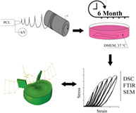
Three types of ES PCL (Mn 80′000 g/mol, Sigma Aldrich Chemistry, 440 744) membranes of distinctly different fiber diameters were produced, as shown in Figure 1. The processing was done under variable electrospinning conditions reported in Table 1, using chloroform (CHCl3, Sigma Aldrich, ReagentPlus, 132 950) and methanol (CH3OH, Fisher Chemicals, HPLC grade, CAS: 67‐56 − 1) solvents. IME Technologies EC‐CLI electrospinning equipment was used with a translation nozzle stage and an 8 cm diameter rotating drum collector rotating at 10 rpm, with a 19 cm spinning distance. The environmental parameters were controlled at 24°C and 40% relative humidity. The resultant mats were cut into pieces of 20 by 70 mm, which were randomly distributed among sample groups (Figure 2), where two randomly selected pieces were treated as a single sample for all tests.
FIGURE 1.

Representative micrographs of three different membranes types used in the study. A, Thin. B, Medium. C, Thick
TABLE 1.
Electrospinning parameters for three fiber diameters used in the study
| Fiber diameter (μm) ± SD | PCL (wt%) | Solution and solvent ratio | Needle inner diameter (mm) | V source (kV) | V collector (kV) | Flowrate (μl/min) |
|---|---|---|---|---|---|---|
| 1.60 ± 0.26 (thin) | 12 | 6:1 CHCl3:CH3OH | 0.6 | 16 | –1 | 27 |
| 3.31 ± 0.21 (medium) | 12 | 7.3:1 CHCl3:CH3OH | 0.8 | 24 | −2 | 26 |
| 6.73 ± 0.51 (thick) | 12 | CHCl3 | 0.8 | 24 | −2 | 26 |
Abbreviation: PCL, poly(ε‐caprolactone).
FIGURE 2.
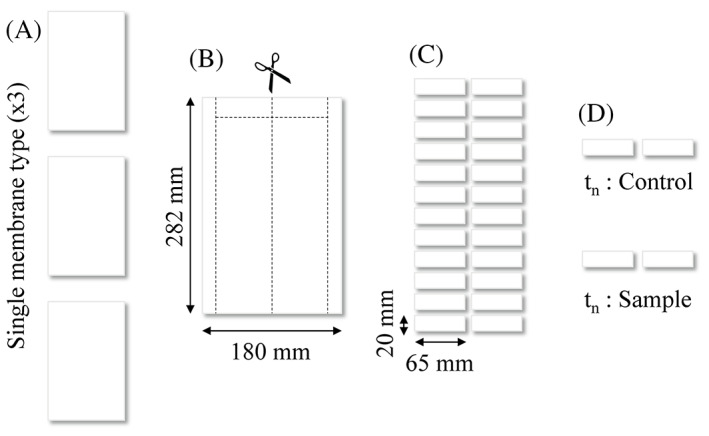
Sample preparation from electrospun mat to single samples. A, Three membranes of the same type are produced. B and C, The membranes are cut into smaller pieces. D, The pieces are randomly separated into groups of four for each time point (tn), which are then split into sample and control group
The membranes were dried in a desiccator under vacuum for 12 hours, then sterilized in 70% alcohol solution for 1 hour followed by drying in a sterile environment for an additional hour. Samples were then separated into two groups with three pieces per group: controls which were kept dry and the sample group which was washed two times with PBS (SIGMA Life Science, pH 7.4) before being submerged in 50 mL of DMEM (DMEM (1x) + GlutaMAX‐I [+] 4.5 g/L D‐Glucose [+] Pyruvate, Gibco by Life Technology) with 1% penicillin‐streptomycin (Gibco, Zug, Switzerland) and 10% Fetal Calf Serum (FCS). All samples were kept at 37°C. The solution was continuously agitated and changed every 2 weeks. Six time points (0, 14, 30, 60, 90, and 180 days) were chosen, at which each sample was washed with PBS, dried and underwent mechanical and material testing.
2.2. Mechanical testing
Three dogbone‐shaped specimens were punched from each sample, producing nine specimens per membrane type per time point in each control and sample group. The samples were washed and dried prior to testing. The length of the specimen between the clamps was 12 mm (Figure 3). These underwent cyclic extension mechanical testing at a strain rate of 0.5 mm/s (4.2 strain %/s)with 4 cycles at each of the six strain steps, each step increasing by 5% (5%, 10%, 15%, 20%, 25%, and 30% strain). In the final step, the membranes were loaded to 150% strain in a single cycle. Engineering stress was calculated from force divided by linear density: σ = F/(wm/Aρ), where F is force, w is width of the dogbone (2 mm), m is mass of the dogbone, A is the area of a face of the dogbone (138 mm2) and ρ is density of PCL (0.001145 g/mm3). To calculate the traditional stress values (force over cross section area) the linear density was divided by porosity fraction of the sample. The porosity values were obtained using dimensional measurements of the samples in the undamaged state combined with the known density of PCL. The thickness of the membrane samples was determined using thickness gage (Käfer Messuhren, Villingen‐Schwenningen, Germany) at a standardized contact pressure of 7.85 kPa (1 N, Ø 10 mm) and with an accuracy of 0.01 mm. Additional parameters such as hysteresis and recovery were also calculated. Hysteresis was calculated as the area under the unloading curve subtracted from the area under the loading curve. The recovery was defined as a strain value between the maximum strain reached in the cycle and when the unloading cycle stress reaches 0 value, at which point the membrane would become slack. All tests were performed in an ambient lab environment, dry at 24°C.
FIGURE 3.
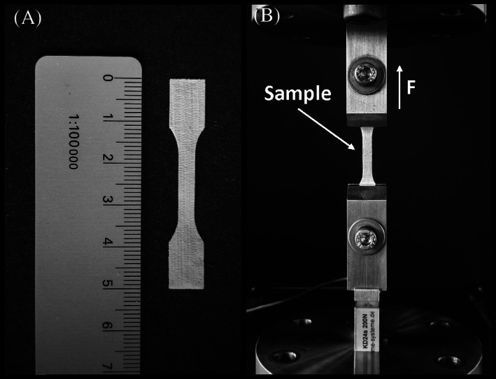
A, Representative dogbone sample. B, Mechanical testing rig and dogbone sample placed in the rig
2.3. Material testing
Dynamic scanning calorimetry (DSC) was performed using a differential scanning calorimeter (DSC 822, Mettler Toledo) with samples exposed to a temperature range from −40 to 100°C with a heating and cooling rate of 10°C/min. The crystallinity change of PCL was determined by comparing the enthalpy of fusion to that of 100% crystalline PCL (139.5 J/g). 36 Attenuated total reflectance (ZnSe crystal)‐Fourier transform infrared spectroscopy (ATR‐FTIR) was performed using a Vertex 70 (Burker Optik GmbH) machine. The spectrum measured was between 500 and 4000 cm−1 with 64 scans. To evaluate the data, it was assumed that carbon‐hydrogen bonds (CH) do not degrade, following, changes in ester bond (C=O) and carboxylic acid bond (COC) peaks were evaluated by the ratio of each to C=O bonds. Three samples per membrane type per time point were tested with these methods.
Reference SEM images were acquired using a Hitachi SU5000 scanning electron microscope to evaluate the visual appearance and change in fiber diameter of the incubated membranes. The images were taken from unused parts (ie, nontested) of the incubated sample at each time point.
2.4. Finite element analysis
To provide context to the mechanical properties for annulus repair membranes, we used the results from a finite element (FE) analysis reported in a previous study, 37 in order to identify the distribution of local strain values for annular tissue during simulated physiological loading of the segment. The parametrized FE model used in the study and the outcomes of that study are only briefly described here for clarity and context (Figure 4). An X‐ray computed tomography scan of a pair of L4‐L5 vertebrae was used to define a generic intervertebral disk shape. These vertebrae were found to be representative of average human anatomy at this level in the spine. 38 The vertebrae were modeled as rigid structures and the facet joints were simplified by two parallel plain surfaces that represent the cartilage layers. The outer shape of the disk was parametrized including the lordotic angle, disk height, endplate shape, and disk bulge. The ratio of nucleus area vs disk area (0.43) was defined according to literature. 39 The nucleus was modeled as an incompressible fluid filled volume. Annulus fiber orientation, which was alternated in each annulus layer, was set to +/− 30° from a horizontal plane. The annulus matrix was assumed to follow a Neo‐Hookean material behavior in accordance with literature. 40 , 41 , 42 Through parametrization of the FE model, new instances of the model were generated by systematically varying the disk height, lordotic angle, and vertebral body size. The disk height and lordotic angle were varied from –1 x SD to +1.5 x SD. The vertebral body size (and thus disk size) was varied from –1 x SD to +1.5 x SD. The FE models were subjected to a range of loading conditions with up to 7.5 Nm being applied in flexion, extension, lateral bending, and torsion respectively. For all loading cases, a compressive follower load of 1000 N was applied.
FIGURE 4.
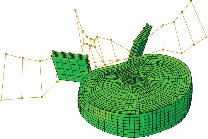
A parameterized finite element (FE) model of a L4‐L5 intervertebral disk. Nine different vertebrae geometries were investigated in the study of Helgason et al. 37 The vertebra body size was varied from −1.5 to +1.5 SD from the average geometry reported by Panjabi et al. 38 The disk height and lordotic angle were varied from −1.0 to +1.5 SD from the average of the values reported by Abuzayed et al 76 the study of Rohlmann et al. 40
2.5. Data post processing and statistics
To evaluate the significance of the effect of fiber diameter and time on the modulus measured on the first loading cycle a two‐way ANOVA was conducted. As the interaction between the factors was found to be significant, simple effects analysis was performed by splitting the samples by thickness and performing a one‐way ANOVA with Turkey's HSD post‐hoc analysis to evaluate the differences between different time points. The analysis was performed in IBM SPSS v26.
To investigate the change in hysteresis and crystalline fraction over time and the effect of strain on modulus measured on the fourth loading cycle linear regression was fitted to the results. Linearity was established by visual inspection of a scatterplot. There was homoscedasticity, as assessed by visual inspection of a plot of standardized residuals vs standardized predicted values. Residuals were normally distributed as assessed by visual inspection of a normal probability plot. The analysis was performed in IBM SPSS v26.
To evaluate the change in ester bond density over time and the elastically recoverable strain with respect to maximum strain, a one phase decay model was used with the following equation: Y = (Y0 − Plateau) * exp(−K * X) + Plateau, where Y is modulus or ester bond density and X is maximum strain level or time, respectively.
The outcome of the mechanical testing was qualitatively compared to the range principal strains from the FE analysis. To achieve this, the tensile principal stress‐strain response was sampled for all nodes on the outer surface of the annulus in the FEMs, where an electro‐spun PCL membrane would be applied as a part of a repair procedure. This was done in steps of 20%, 40%, 60%, 80%, and 100% of the max loading, for all the FE model geometries and loading cases simulated. These results should conceptually represent the range of appropriate candidate implant material strains for annulus surface repair.
3. RESULTS
3.1. Morphology
Three types of membranes were produced for this study with three different sets of electrospinning parameters. These membranes differed significantly primarily in their fiber diameter, as measured through electron microscopy (Figure 1). The SEM micrographs were taken at each time point and the membranes did not show any change in fiber diameter with incubation time. No changes in the appearance of the fibers and inter fiber bonds were observed at any time point. In addition, fibers submerged in medium and kept dry showed no differences.
3.2. Mechanical testing
Young's modulus measured at each time point for both dry and submerged samples showed an increase over time for all membranes. No significant difference between the data from dry and submerged membranes could be detected. Therefore, the results shown in Figure 5 are only for the submerged samples. A large and significant difference in modulus was observed between membranes made up of fibers of different diameters, where thinner fibers showed higher modulus, as seen in Figure 5. For samples with thin fibers at 1.60 ± 0.26 μm fiber thickness, modulus was 32.80 ± 6.43 MPa, medium samples with fiber thickness of 3.31 ± 0.21 μm had a modulus of 24.71 ± 2.74 MPa and for samples with thick fibers of 6.73 ± 0.51 μm diameter, and the modulus was 10.55 ± 2.58 MPa. However, there was a statistically significant interaction between the effects of fiber diameter and time on modulus, F (10, 306) = 1.859, P = .05. Leading to the conclusion that the incubation time affects fibers of different thickness differently. Simple main effects analysis showed that the effect of time is significant for the three fiber diameters. Specifically for the thin fibers (1.6 μm) F (5, 102) = 12.190, P = .000; the medium fiber diameter (3.31 μm) F (5, 102) = 6.885, P = .000; and thick fiber diameter (6.73 μm) F (5, 102) = 8.223, P = .000. Furthermore, it was found the onset of the significant change in modulus was at a different time point. The samples made up of the thinnest fibers showed a significant increase (41%) after 14 days with no further changes, the medium fiber diameter samples showing an increase (34%) after 30 days, and the thickest fiber diameter samples showing an increase (43%) after 90 days only. In addition, the thickest fiber diameter samples showed another change after 180 days, which was significantly higher from 0, 14, 30, and 60 days.
FIGURE 5.
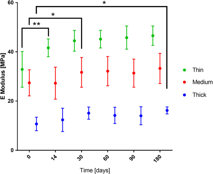
The effect of incubation time on Young's modulus of the first loading cycle of three types of samples. n = 9, * P < .05, ** P < .005. n = 18
The modulus measured on the fourth loading cycle was assessed relative to the maximum strain reached during the cycle and grouped with respect to the membrane type and time, as shown in Figure 6. The data is presented in seven strain steps from 5% to 35% and constant step size of 5%, grouped by membrane and time point. The results for the inverse correlation that was established for modulus with respect to strain step are summarized in Table 2. The magnitude of the inter‐strain reduction increased with time for all types of membranes, the change was larger for membranes made up of thinner fibers. The magnitude of the effect the strain had on modulus is characterized by the R2 and R2adj values in Table 2 show overall a medium to large effect, 43 with the exception of day 0 of the membrane made up of thin fibers where there was a small effect. Furthermore, the intercept which represents a theoretical zero damage modulus for the membranes increased over time for the two membranes made up of thinner fibers (1.6 and 3.31 μm), while staying unchanged up to 180 days for the membrane made up of thickest fibers (6.73 μm).
FIGURE 6.
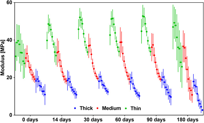
Graph showing change of Young's modulus. Seven consecutive 5% strain steps from 5% strain are shown grouped by membrane type at each time point. n = 18
TABLE 2.
Summary of the results obtained from fitting linear regression model to assess the effect of maximum strain on modulus measured on the fourth loading cycle. The model fitting was significant for all groups with P < .0005, n = 18
| Thin | |||||||
|---|---|---|---|---|---|---|---|
| Day | 0 | 14 | 30 | 60 | 90 | 180 | Mean |
| Slope | −.335 | −.442 | −.540 | −.551 | −.581 | −.727 | −.529 |
| Slope (95% CI) | (−.500, −.171) | (−.567, −.408) | (−.604, −.486) | (−.625, −.477) | (−.654, −.526) | (−.961, −.576) | |
| Intercept | 38.857 | 48.571 | 52.465 | 53.180 | 53.826 | 50.342 | 49.540 |
| Intercept (95% CI) | (35.173, 42.54) | (47.330, 50.895) | (51.321, 53.969) | (51.528, 54.832) | (52.672, 55.517) | (46.141, 54.544) | |
| R2, R2adj | .116, .109 | .607, .604 | .770, .768 | .637, .634 | .739, .737 | .325, .319 | 0.532, 0.529 |
| Medium | |||||||
| Day | 0 | 14 | 30 | 60 | 90 | 180 | Mean |
| Slope | −.374 | −.536 | −.567 | −.625 | −.597 | −.909 | −.601 |
| Slope (95% CI) | (−.470, −.341) | (−.621, −.483) | (−.636, −.528) | (−.691, −.559) | (−.665, −.528) | (−1.028, −.791) | |
| Intercept | 32.709 | 35.380 | 37.487 | 39.166 | 37.761 | 38.024 | 36.755 |
| Intercept (95% CI) | (31.271, 34.148) | (33.836, 36.924) | (36.286, 38.687) | (37.682, 40.650) | (36.231, 39.292) | (35.380, 40.668) | |
| R2, R2adj | .561, .557 | .673, .670 | .801, .800 | .737, .735 | .706, .704 | .651, .649 | 0.688, 0.686 |
| Thick | |||||||
| Day | 0 | 14 | 30 | 60 | 90 | 180 | Mean |
| Slope | −.278 | −.300 | −.267 | −.296 | −.341 | −.389 | −.312 |
| Slope (95% CI) | (−.318, −.207) | (−.356, −.248) | (−.321, −.234) | (−.374, −.268) | (−.414, −.268) | (−.483, −.348) | |
| Intercept | 20.192 | 20.246 | 20.950 | 20.309 | 20.393 | 16.626 | 19.786 |
| Intercept (95% CI) | (18.956, 21.429) | (19.033, 21.459) | (19.980, 21.921) | (19.131, 21.486) | (18.767, 22.020) | (15.115, 18.136) | |
| R2, R2adj | .485, .480 | .541, .537 | .564, .561 | .544, .540 | .409, .405 | .562, .558 | 0.518, 0.514 |
The hysteresis between the loading and unloading energy was calculated for the first loading cycle of each strain step and time point for the three sample groups, as seen in Figure 7. Seven strain steps from 5% to 35% at a constant step size of 5% are shown. Values were normalized to time point 0 at the corresponding strain steps. Here once again the submerged sample group and the dry samples did not show a significant difference. Since material properties were also consistent for both groups, the results were pooled. Fiber diameter and time both had a significant impact on the hysteresis. Membranes made up of fibers of different diameters showed significantly different hysteresis. All membranes showed a significantly lower hysteresis after 180 days. The change in hysteresis with respect to the maximum strain was not significant for thin samples, while medium and thick samples showed a significant correlation.
FIGURE 7.
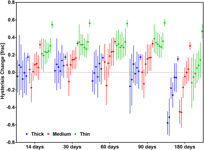
Graph showing change of hysteresis normalized 0 time point. Seven consecutive 5% strain steps are shown grouped by membrane type at each time point. Time showed a significant effect on the change in hysteresis for all samples (P < .05). Fiber diameter shows a strongly significant effect on this change (P < .0005), as well as the strain level for the Medium (P < .05) and thick sample (P < .05). n = 9
Similarly, to Figures 6 and 7, in Figure 8 the results for elastically recovered strain were grouped with respect to membrane type and time, as well as seven strain steps from 5% to 35% and constant step size of 5% are shown in each group. At 5% maximum strain the elastic range was not significantly different from the maximum strain. Above 5% the recovery was consistently lower than the maximum strain reached with an increasing fractional decrease. The elastically recoverable strain over the whole testing period with preconditioning to 35% strain was 22.19% ± 1.320 SD for samples made up of thin fibers (1.6 μm), 22.48% ± 1.397 SD for medium (3.31 μm) fibers and 19.6% ± 1.9 SD for the thick (6.73 μm). Recovery against maximum strain was evaluated using a one phase decay function at each time point individually, shown in Figure 9. This evaluation produced two values K and plateau. The plateau value shows the maximum recovery that can be reached by the sample and how it changes with incubation type. The K value shows how quickly the recovery plateau is reached with respect to maximum strain. The membranes were tested up to 150% strain without failure in all membrane types and all time‐points in this study.
FIGURE 8.
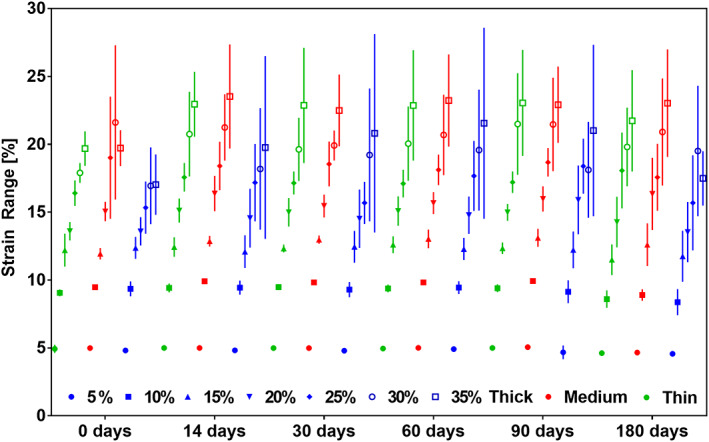
Graph showing change in elastically recovered strain in % strain calculated at consecutive 5% maximum strain steps grouped by membrane type at each time point. n = 18
FIGURE 9.
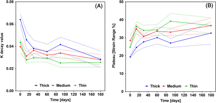
K (A) and Plateau (B) values for the one phase decay fitted to recovery against maximum strain data grouped by time point and membrane type. n = 5
3.3. FE model
In this study, the strain environment of human IVDs under severe loading was assessed across a wide spectrum of human IVD anatomies, and it was found based on the frequency plots that a small portion of the IVD may experience local first and third principle logarithmic strains that are at or slightly above 40%. The frequency of strains recorded in annulus tissue according to the FEM results is illustrated in Figure 10 to provided context for the resilience requirements on the ES membranes for annulus fibrosus (AF) repair.
FIGURE 10.
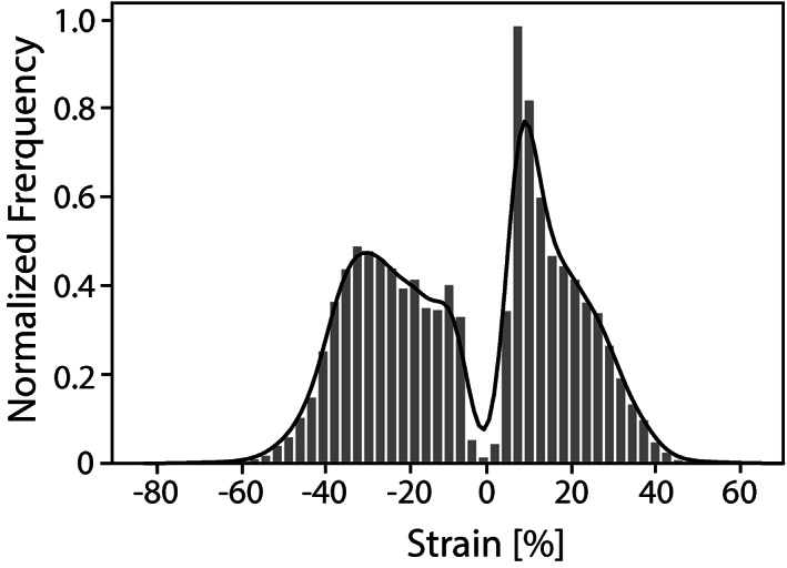
Graph showing normalized frequency of strains predicted by the finite element (FE) model
3.4. Material testing
The change of ester bond is reported as a fraction of C—C bonds. Figure 11 shows the change of ester bond fraction over time for the three different membranes, normalized to time point 0. A significant decrease in relative ester bond density is indicative of hydrolytic degradation of PCL, which would lead to shortening of polymer chains. No difference was found between the submerged samples and those kept dry; therefore, the results presented are only for the submerged samples. A one‐phase decay function was fitted to the data. It was found that the decay exponential K (mean ± SE) increased with increasing fiber thickness of the membrane: 0.016 (±0.011) for thin fibers, 0.028 (±0.013) for medium and 0.058 (±0.015) for thick fibers.
FIGURE 11.
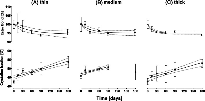
Change of ester bond density against time grouped by sample type, A, membrane made up of thin fiber (1.6 μm), B, medium fibers (3.31 μm) and C, thick fibers (6.73 μm). Crystalline fraction is represented with respect to time and grouped by the same sample types
The crystalline fraction increased in membranes of all three types from approximately 42‐45% to 50‐55%. The submerged group did not have significantly different results from the dry group, therefore the results only shown for the submerged samples in Figure 11. The three types of membranes were not significantly different from each other in crystalline fraction or recrystallization rate. A linear regression model was fit to the crystalline fraction over time data. The model showed a significant fit for all three types of membranes with a strong to medium effect of time on crystalline fraction 43 summarized in Table 3.
TABLE 3.
Summary of linear regression model fitted to the crystallinity over time data for three types of membranes used in the study. n = 34
| Fiber diameter (μm) ± SD | Intercept (% crystallinity) | Slope (% crystallinity/day) | R2, R2 adj | Model | P |
|---|---|---|---|---|---|
| 1.60 ± 0.26 (thin) | 45.3 | 0.718 | 0.516, 0.501 | F(1,32) = 34.126 | <.0005 |
| 3.31 ± 0.21 (medium) | 47.1 | 0.634 | 0.402, 0.381 | F(1,28) = 18.819 | <.0005 |
| 6.73 ± 0.51 (thick) | 44.3 | 0.635 | 0.404, 0.385 | F(1,32) = 21.671 | <.0005 |
4. DISCUSSION
In the scope of intervertebral disk repair using ES membranes as a mechanical support, this study aimed to establish the influence of fiber diameter on the mechanical and material properties of ES membranes not only directly after production but also following extended exposure to conditions similar to those found in vivo. No statistically significant difference between membranes kept in solution and membranes kept dry over the whole period were found for any of the investigated parameters. Therefore, only the results for those samples kept in solution are discussed. Finally, the membrane functional limits were found to fall within the range of the targeted strain range of annulus fibrous tissue under physiological loading as assessed by comparison with computational model.
The choice of solution and electrospinning parameters in this study was based on a common parameter set, widely used to produce membranes for in vivo and in vitro applications. 44 These membranes can be easily sterilized using a variety of methods, while the methanol and chloroform solvent has been shown to completely evaporate after vacuum treatment and be nontoxic. 45 As these membranes are intended for in vivo applications, fiber diameters chosen for this study were based on the range deemed useful in such applications. Considerations such as cell proliferation, infiltration, and nutrient delivery are of utmost importance for cell viability, and require porosity size on the scale of micrometer, 46 which is in turn largely dependent on fiber diameter especially in the plane orthogonal to the spinning direction.
4.1. Evolution of mechanical properties
Direct assessment of the mechanical properties post long‐term (>1 week) in vivo implantation is not possible due to integration of soft tissue, 31 , 34 therefore, the study was carried out in vitro. The appearance of membranes as well as material properties was evaluated at each time point up to 6 months (180 days). The mechanical properties were assessed through cyclic tensile loading. Degradation has been shown to proceed though hydrolytic cleavage of ester bonds in PCL, 18 , 22 consequently dry state at 37°C was chosen as control for the study.
In this study, fiber diameter and morphology were observed using SEM and showed no change throughout the incubation period. There is a consensus in literature that PCL does not show mass loss and dimensional changes when exposed to aqueous solutions such as PBS at 37°C for up to 6 months. A study by Lam et al showed no morphological differences were observed after exposure up to 6 months, due to very low mass loss on the order of 1% that was observed. 19 No changes in fiber diameter were also observed by Li et al after 2 month. 47 Insignificant mass loss was also observed by multiple other studies in PBS over a period of 7 days to 2 month. 26 , 27 , 28 , 48 In addition depending on the medium that the membranes are kept in the mass can even increase, as was shown in plasma by Johnson et al. 33
The density of PCL for the purpose of calculating modulus for comparison with literature was assumed to have been unchanged throughout the experiment, this assumption is supported by only minor degradation observed in the samples. The porosity and dimensional changes were observed and quantified throughout the experiment at each time point and have shown no variation at all.
The tensile linear modulus of the membranes was in the range of other studies that performed uniaxial tensile tests. For mats made up of thin (1.60 μm) fibers, the modulus when accounted for porosity was 6.57 to 9.32 MPa though out the 6 month period, which the range found in literature of 8.5 to 17.5 MPa, 20 , 47 , 49 , 50 , 51 , 52 , 53 for fibers of broadly similar diameter. For mats made up of medium (3.31 μm) Kim et al measured 7.6 ± 0.7 MPa on fibers 3.43 ± 0.57 μm, 52 compared to 4.93 ± 0.95 MPa measured in this study. No definitive data is available in literature on ES PCL fibers in the order of the thick (6.73 μm) fibers used in this study. However, the 1.6 ± 0.41 MPa modulus adjusted for porosity in this study is well in line with the trend from the measurements from the thinner fibers. Overall, the values of linear tensile modulus for ES PCL membranes in this study fall within in the lower range from the values previously described in literature.
The modulus of the membranes increased with time when measured only on the first loading cycle; however, the significant change occurred later for membranes made up of fibers of higher diameter. This finding is consistent with previous studies, 19 , 30 which also showed an increase in modulus when exposed to elevated temperatures in PBS and DMEM, theorized to be due to annealing leading to an increase in crystallinity. However, the variation in the onset of the change in the modulus is not directly correlated with the change in crystallinity in this study, as the rate of increase of crystallinity was rather linear and not significantly different between different fiber diameters. When the membranes were exposed to repeated strains in the region where plastic losses were significant (above 5%), there was an overall decrease in modulus linearly correlated with increase in strain, due to damage incurred in the previous cycles. This finding is supported by previous studies, 25 where the likely explanation is breakage of weak inter‐fiber bonds, which lead to softening. Evidently this damage is not significant up to 5% strain as the modulus increased after loading up to 5% due to work hardening. The rate of modulus decrease with increasing strain above 5% increased with incubation time. This phenomenon can be explained by the increase in crystalline fraction and degradation of the polymer over time, which leads to the material being more prone to damage at lower strains. This consideration is paramount for adequate design of the ES PCL implants in the scope of biomedical applications with load bearing capability.
The difference in energy of the loading curve and the unloading curve (ie, hysteresis) was quantified on the first loading cycle at each strain level (Figure 7). However, the mechanism by which the change in hysteresis occurs was not analyzed in detail in this study as the complex network and material interactions require a focused set of experiments and models aimed at understanding the combination of plastic and viscoelastic behavior of the samples, which is beyond the scope of this study. Other studies have suggested fiber reorientation as the source of hysteresis. 33 This mechanism could explain the increase in hysteresis with increasing maximum strain, as fibers need to move more to accommodate the deformation. As well as the overall decrease with incubation time, as the material becomes stiffer the capacity for nondestructive fiber motion decreases.
Recovery, defined as a reproducible range at which the membrane exhibits an elastic response, was measured at each maximum strain step. The elastic response of the material can be modified through preconditioning steps, as evidenced by the results in this study where it can be observed that the recovery increased significantly with increasing maximum strain reached on the first loading cycle. The first loading cycle can also be considered a preconditioning step that would eliminate the need to account for the slack in the membrane after the plastic deformation. The increase in elastic range with increasing preloading strain can be explained by plastic deformation of the underlying fibers and breakage of the inter‐fiber linkages, which leads reduction in fiber interconnection density and consequent loosening of the network allowing for strain without plastic loss, this finding is supported by observations by Duling et al. 25 Although PCL has a significant plastic character, as was hypothesized a useful elastic range can be accessed through this practice. In addition, the mechanical response is similar to that of natural collagen matrix, as it stems from a similar fiber realignment mechanism. 54
4.2. Degradation of the ES membranes
The change in material properties observed during the exposure of the membranes to DMEM at 37°C was quantified using DSC measurements and IR‐spectroscopy. These measurements provided two main values: crystalline fraction and ester bond density respectively. Crystalline fraction did not differ significantly between samples made up of fibers of different diameter. Comparing this to literature is difficult as we are not aware of any studies that measured this directly on samples produced with similar methods and in this fiber diameter range for PCL. The crystalline fraction increased linearly as a function of time at elevated temperature as seen from Figure 11. This is consistent with previous findings in vivo extruded thin PCL fibers as well as other semicrystalline ES polymers and is due to annealing that is accelerated at temperatures close to glass transition. 19 , 55
The ester bond density was used to assess the degradation of PCL through ester bond cleavage and establish the rate of this process. The degradation of bulk PCL has been theorized by Sun et al to proceed through random chain scission in vitro, as the rate of molecular weight decrease with time was independent of geometry and aqueous solution constituents in vitro. 22 Lam et al 19 did not support this view since the implied bulk autocatalytic cleavage of ester bonds should show an increase in degradation rate over time, which was not observed in their study. This can be explained by vastly different geometry of the implanted samples of the two studies, where the earlier study used bulk samples while the later thin fibers. Lack of bulk autocatalytic process is consistent with the findings of this study, where the fibers are still a magnitude thinner than those used by Lam et al. The reduction in ester bonds showed an exponential decay behavior with a characteristic slowdown in the degradation after a certain time period. The rate of decay (k) showed a positive linear correlation with the fiber diameter. This finding implies surface area controlled process, as when the easily accessible surface region is degraded, the bond cleavage that relies on hydration, proceeds at much slower pace in the bulk. Hence, thick fibers reached the plateau degradation state much quicker than thin fibers that have much more surface relative to bulk.
A direct linear relationship between modulus and crystalline fraction has been observed experimentally in ES single fibers of similar semicrystalline polymers 56 as well as theoretically. 57 The membranes made up of medium diameter fibers showed an anomalous measurement at time point 180 days that was inconsistent with possible material behavior as well as with observations found in literature and membranes with fibers of other diameters. Therefore, this measurement was excluded from the regression calculations. The linear relationship observed in this study characterizes the crystalline fraction for the time period of the observations. The linear model is only valid to predict this behavior for the 6 month observation period, as in the long‐term the crystalline fraction will likely tend to a steady state and therefore should be characterized by log linear function. However, as no data was generated for the long‐term response, fitting such a function was not appropriate. In this study, while the crystalline fraction increased linearly with time, modulus did not show the same relationship. This can be due to degradation, characterized here as change in ester bond density which leads to the reduction of the molecular weight of the polymer. It is expected that on the material level the effect on modulus from change in molecular weight would be small, while the largest effect is on strain at break, which decreases with decreasing molecular weight based on research done on semicrystalline polymers. 58 The mismatch between the expected change in material properties and observations on ES networks arise from the complex fiber‐fiber interactions which play a key role during fiber reorientation under stress. 56 , 59 In particular, inter‐fiber adhesion, which plays one of the key roles, 60 is affected by reduction in elongation at break as well as stiffening of material. It is therefore likely that the nonlinear relationship between network modulus and incubation time is a result of interplay between the increasing modulus of the fibers and decreasing resilience of the inter‐fiber bonds. This is qualitatively supported by the increasing difference between the hysteresis at low strains and high strains with time. The hysteresis in this study represents plastic energy loss after the first loading cycle. It suggests that at low strains, where the effect of inter‐fiber interactions is low the networks were less prone to plastic deformation, while at high strains this was not the case due to weakening of the inter‐fiber bonds. Paralleling this observation, the magnitude of the inter‐strain reduction in modulus with increasing strain increased with time for all types of membranes. This is likely due to the same effect imparted by the failure of inter‐fiber links, which provide a reinforcing effect on the network. 59 The breakage occurs more easily at later time points, therefore the modulus reduction is higher. The complexity of the interaction of the effects of material parameters coupled with the network behavior under stress puts a constitutive mathematical model outside the scope of this study. In conclusion, it was found that to arrive at a more conclusive relationship between the parameters discussed, microscopic 3‐dimensional observation of the network deformation is required to distinguish the contribution of the changes in the material properties to the individual fiber segments and fiber‐fiber interactions. A simplified empirical regression model did not lead to statically significant interaction of the crystalline fraction, ester bond density, and modulus of the membranes.
4.3. Mechanical properties in the context of AF repair
4.3.1. ES membranes compared to AF tissue level response
There is a large body of literature that investigates the tissue level mechanical response of the AF extracted from human IVDs. These measurements done on multiple AF lamellae bundles loaded in the IVD's circumferential direction provide context for the stiffness and strength that is required of ES membranes to provide mechanical support. The linear tensile modulus obtained from tissue level circumferential AF measurements in literature are contextualized in Figure 12. 61 , 62 , 63 , 64 , 65 , 66 , 67 , 68 , 69 , 70 , 71 , 72 The comparison shows that there is an overlap at the lower range of the mechanical response of the AF and the upper range of the PCL membrane properties used in this study. Furthermore, the scale of changes in the modulus due to aging of the material under in vitro conditions utilized in this study is negligible compared to the uncertainty of the mechanical properties of the AF. These results are promising for the use of ES PCL membranes as load bearing scaffolds in AF repair. With the addition of adhesives, 73 , 74 and cell seeding techniques, 29 , 47 the stiffness can be further increased if required.
FIGURE 12.
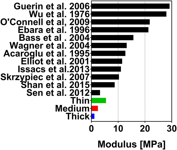
Mean, maximum, and minimum tensile linear modulus of electrospun membranes obtained on the last loading cycle with a maximum strain of 35% from all time points combined with circumferential linear moduli from tissue level AF response found in literature 62 , 63 , 64 , 65 , 66 , 67 , 68 , 69 , 70 , 71 , 72 , 73 visualized as stress vs strain curves
4.3.2. FE model comparison
Local strain levels in the disk under complex physiological loading conditions were predicted. This provides complementary data to the tissue level response, where tissue samples are tested in uniaxial tension. The plateau value from Figure 9 which describes the maximum theoretically possible value that the elastically recoverable strain can reach at a given time point, suggests that recoverable strain in excess of 30% is achievable for the ES membranes produced in this study. To achieve the desired elastic response it is important to consider the preconditioning to prepare the membranes for the strains that will be present in vivo and access the hyperplastic J‐curve response observed after preconditioning. Comparing this finding with the normalized frequency of the occurring strains in the AF in Figure 10 shows that a small number of loading cases invoke strains in excess of 40%. Similar values for the strains experienced by the outer layers of the AF when tested on the organ level have been described in literature by Skrzypiec et al 40% ± 11 SD 75 and Shan et al 38.1% ± 13.1 SD. 71 Others recorded even lower strains at failure of 13% to 25%. 62 , 66 , 69 The strains above the elastically recoverable range would lead to a degree of plastic deformation and slack in the membrane. However, the samples exhibited exceedingly high tolerance to tearing up to 150% strain, which means that a mechanical seal is guaranteed at the application site even if design strains are exceeded, which is important for maintaining organ isolation and integrity in vivo. While the ES samples were only tested in uniaxial tension, and the true strains are not assessed in this study, the high levels of resilience provide a promising result for their use in AF repair applications.
In this study, it was possible to clearly establish the effect of an in vitro environment on the modulus and recovery in biomechanically relevant loading conditions for ES PCL networks. The effect of incubation produced clear trends and allowed to obtain valuable design guidelines for the membranes. Furthermore, the comparison of the mechanical behavior of the synthetic membranes to the in silico model showed promising biomechanical compatibility of these constructs. However, the study was carried out without the presence of live cells, which can significantly affect the environment through enzymatic activity and induce significant changes to the material properties of the membranes. Introduction of live cells to the experimental design would have led to difficulties with accessing the changes mechanical and material properties of the membrane due to the presence of additional matter. In particular, distinguishing the mechanical changes attributed to the change in the membrane and those produced by cell proliferation. Furthermore, the cyclic experiments were carried out at only a single frequency, which meant that the viscoelastic properties of the material could not be assessed. No control group at room temperature was assessed, however, such group would most likely have similar evolution to the group kept dry at elevated temperature, as observed by studies on various bulk polymers, and therefore would not provide any valuable insight.
5. CONCLUSION
In summary, the mechanical properties of ES PCL membranes of varying fiber diameters were investigated at different time points after exposure to cell culture medium at elevated temperature. The membranes showed stiffening and an increase in modulus with decreasing fiber diameter, as well as with longer incubation times. Furthermore, the modulus decreased with repeated cycles of increasing strain. The recovery after preconditioning increased with higher strain levels and did not vary significantly with incubation time. The magnitude of recoverable strain with a preconditioning cycle reached a theoretical maximum of approximately 30%, which is in the range for many biomechanical applications. The results of the physical investigation were compared to predictions of an in silico model of intervertebral disk, where the strains experienced by the annulus fibrosus were investigated. The strain tolerance of the membranes showed a promising correspondence to the values observed in silico as well as experimental results from literature for native human disk tissue under physiological loading.
AUTHOR CONTRIBUTIONS
Dmitriy Alexeev substantially contributed to the conception of the work, acquisition, and analysis; as well as, drafting and revising of the manuscript. Melanie Tschopp substantially contributed to the acquisition and analysis of the data, as well as revising of the manuscript. Benedikt Helgason substantially contributed to the conception of the work, analysis, data interpretation, and revising of the manuscript. Stephen J. Ferguson substantially contributed to the conception of the work, data interpretation, and revising of the manuscript.
ACKNOWLEDGMENTS
The authors thank Dr Kirill Feldman and the Soft Materials group at the Department of Materials at ETH Zurich for support with materials testing procedures. This work was supported by the Swiss National Science Foundation (grant number 155918) and the AO Foundation, Switzerland (AO Collaborative Research Program for Annulus Fibrosus Repair).
Alexeev D, Tschopp M, Helgason B, Ferguson SJ. Electrospun biodegradable poly(ε‐caprolactone) membranes for annulus fibrosus repair: Long‐term material stability and mechanical competence. JOR Spine. 2021;4:e1130. 10.1002/jsp2.1130
Funding information AO Foundation: AO Collaborative Research Program for Annulus Fibrosus Repair; Schweizerischer Nationalfonds zur Förderung der Wissenschaftlichen Forschung, Grant/Award Number: 155918
REFERENCES
- 1. Sell SA, Wolfe PS, Garg K, McCool JM, Rodriguez IA, Bowlin GL. The use of natural polymers in tissue engineering: a focus on electrospun extracellular matrix analogues. Polymers (Basel). 2010;2(4):522‐553. [Google Scholar]
- 2. Cai S, Xu H, Jiang Q, Yang Y. Novel 3D electrospun scaffolds with fibers oriented randomly and evenly in three dimensions to closely mimic the unique architectures of extracellular matrices in soft tissues: fabrication and mechanism study. Langmuir. 2013;29(7):2311‐2318. [DOI] [PubMed] [Google Scholar]
- 3. Chen ZG, Wang PW, Wei B, Mo XM, Cui FZ. Electrospun collagen‐chitosan nanofiber: a biomimetic extracellular matrix for endothelial cell and smooth muscle cell. Acta Biomater. 2010;6(2):372‐382. [DOI] [PubMed] [Google Scholar]
- 4. Van Lieshout MI, Vaz CM, Rutten MCM, Peters GWM, Baaijens FPT. Electrospinning vs knitting: two scaffolds for tissue engineering of the aortic valve. J Biomater Sci. Polym Ed. 2006;17(1):77‐89. [DOI] [PubMed] [Google Scholar]
- 5. Balguid A, Mol A, van Marion MH, R. A. Bank , Bouten CVC, Baaijens FPT. Tailoring fiber diameter in electrospun poly(ɛ‐Caprolactone) scaffolds for optimal cellular infiltration in cardiovascular tissue engineering. Tissue Eng Part A. 2009;15(2):437‐444. [DOI] [PubMed] [Google Scholar]
- 6. Vaz CM, van Tuijl S, Bouten CVC, Baaijens FPT. Design of scaffolds for blood vessel tissue engineering using a multi‐layering electrospinning technique. Acta Biomater. 2005;1(5):575‐582. [DOI] [PubMed] [Google Scholar]
- 7. Reed CR, Han L, Andrady A, et al. Composite tissue engineering on polycaprolactone nanofiber scaffolds. Ann Plast Surg. 2009;62(5):505‐512. [DOI] [PubMed] [Google Scholar]
- 8. Chen M, Michaud H, Bhowmick S. Controlled vacuum seeding as a means of generating uniform cellular distribution in electrospun polycaprolactone (PCL) scaffolds. J Biomech Eng. 2009;131(7):74521. [DOI] [PubMed] [Google Scholar]
- 9. Possin K. L., Filoteo J. V., Song D. D., and Salmon D. P., “NIH Public Access,” vol. 22, no. 5, pp. 585‐595, 2010. [Google Scholar]
- 10. Li X, Xie J, Lipner J, Yuan X, Thomopoulos S, Xia Y. Nanofiber scaffolds with gradations in mineral content for mimicking the tendon‐to‐bone insertion site. Nano Lett. 2009;9(7):2763‐2768. [DOI] [PMC free article] [PubMed] [Google Scholar]
- 11. Gullbrand SE, Ashinsky BG, Bonnevie ED, et al. Long‐term mechanical function and integration of an implanted tissue‐engineered intervertebral disc. Sci Transl Med. 2018;10(468):eaau0670. [DOI] [PMC free article] [PubMed] [Google Scholar]
- 12. Nerurkar NL, Baker BM, Sen S, Wible EE, Elliott DM, Mauck RL. Nanofibrous biologic laminates replicate the form and function of the annulus fibrosus. Nat Mater. 2009;8:986‐992. [DOI] [PMC free article] [PubMed] [Google Scholar]
- 13. Lowery JL, Datta N, Rutledge GC. Effect of fiber diameter, pore size and seeding method on growth of human dermal fibroblasts in electrospun poly(ɛ‐caprolactone) fibrous mats. Biomaterials. 2010;31(3):491‐504. [DOI] [PubMed] [Google Scholar]
- 14. Wang S, Zhong S, Lim CT, Nie H. Effects of fiber alignment on stem cells‐fibrous scaffold interactions. J Mater Chem B. 2015;3:3358‐3366. [DOI] [PubMed] [Google Scholar]
- 15. Saino E, Focarete ML, Gualandi C, et al. Effect of electrospun fiber diameter and alignment on macrophage activation and secretion of proinflammatory cytokines and chemokines. Biomacromolecules. 2011;12(5):1900‐1911. [DOI] [PubMed] [Google Scholar]
- 16. Bose S, Roy M, Bandyopadhyay A. Recent advances in bone tissue engineering scaffolds. Trends Biotechnol. 2012;30(10):546‐554. [DOI] [PMC free article] [PubMed] [Google Scholar]
- 17. Zhong SP, Zhang YZ, Lim CT. Tissue scaffolds for skin wound healing and dermal reconstruction. Wiley Interdiscip Rev Nanomedicine Nanobiotechnol. 2010;2(5):510‐525. [DOI] [PubMed] [Google Scholar]
- 18. Ali SAM, Zhong SP, Doherty PJ, Williams DF. Mechanisms of polymer degradation in implantable devices. I. Poly(caprolactone). Biomaterials. 1993;14(9):648‐656. [DOI] [PubMed] [Google Scholar]
- 19. Lam CXF, Hutmacher DW, Schantz J‐T, Woodruff MA, Teoh SH. Evaluation of polycaprolactone scaffold degradation for 6 months in vitro and in vivo. J Biomed Mater Res Part A. 2009;90A(3):906‐919. [DOI] [PubMed] [Google Scholar]
- 20. Patel HN, Garcia R, Schindler C, et al. Fibro‐porous poliglecaprone/polycaprolactone conduits: synergistic effect of composition and in vitro degradation on mechanical properties. Polym Int. 2015;64(4):547‐555. [DOI] [PMC free article] [PubMed] [Google Scholar]
- 21. Sun H, Mei L, Song C, Cui X, Wang P. The in vivo degradation, absorption and excretion of PCL‐based implant. Biomaterials. 2006;27(9):1735‐1740. [DOI] [PubMed] [Google Scholar]
- 22. Pitt CG, Chasalow FI, Hibionada YM, Klimas DM, Park T, Carolina N. Aliphatic polyesters I. The degradation of poly (e‐ caprolactone) in vivo. J Appl Polym Sci. 1981;26(11):3779‐3787. [Google Scholar]
- 23. Arinstein A, Burman M, Gendelman O, Zussman E. Effect of supramolecular structure on polymer nanofibre elasticity. Nat Nanotechnol. 2007;2:59‐62. [DOI] [PubMed] [Google Scholar]
- 24. Lim CT, Tan EPS, Ng SY. Effects of crystalline morphology on the tensile properties of electrospun polymer nanofibers effects of crystalline morphology on the tensile properties of electrospun polymer nanofibers. Appl Phys Lett. 2008;141:908. [Google Scholar]
- 25. Duling RR, Dupaix RB, Katsube N, Lannutti J. Mechanical characterization of electrospun polycaprolactone (PCL): a potential scaffold for tissue engineering. J Biomech Eng. 2008;130(1):11006. [DOI] [PubMed] [Google Scholar]
- 26. Tiǧli RS, Kazaroǧlu NM, Maviş B, Gumusderelioglu M. Cellular behavior on epidermal growth factor (EGF)‐immobilized PCL/gelatin nanofibrous scaffolds. J Biomater Sci Polym Ed. 2011;22(1‐3):207‐223. [DOI] [PubMed] [Google Scholar]
- 27. Chung AS, Hwang HS, Das D, Zuk P, McAllister DR, Wu BM. Lamellar stack formation and degradative behaviors of hydrolytically degraded poly(ε‐caprolactone) and poly(glycolide‐ε‐caprolactone) blended fibers. J Biomed Mater Res‐Part B Appl Biomater. 2012;100 B(1):274‐284. [DOI] [PubMed] [Google Scholar]
- 28. Baker BM, Nerurkar NL, Burdick JA, Elliott DM, Mauck RL. Fabrication and modeling of dynamic multipolymer nanofibrous scaffolds. J Biomech Eng. 2009;131(10):101012. [DOI] [PMC free article] [PubMed] [Google Scholar]
- 29. Sant S, Iyer D, Gaharwar AK, Patel A, Khademhosseini A. Effect of biodegradation and de novo matrix synthesis on the mechanical properties of valvular interstitial cell‐seeded polyglycerol sebacate‐polycaprolactone scaffolds. Acta Biomater. 2013;9(4):5963‐5973. [DOI] [PMC free article] [PubMed] [Google Scholar]
- 30. Bölgen N, Menceloǧlu YZ, Acatay K, Vargel I, Pişkin E. In vitro and in vivo degradation of non‐woven materials made of poly(ε‐caprolactone) nanofibers prepared by electrospinning under different conditions. J Biomater Sci Polym Ed. 2005;16(12):1537‐1555. [DOI] [PubMed] [Google Scholar]
- 31. Pektok E, Nottelet B, Tille JC, et al. Degradation and healing characteristics of small‐diameter poly(ε‐caprolactone) vascular grafts in the rat systemic arterial circulation. Circulation. 2008;118(24):2563‐2570. [DOI] [PubMed] [Google Scholar]
- 32. Sung HJ, Meredith C, Johnson C, Galis ZS. The effect of scaffold degradation rate on three‐dimensional cell growth and angiogenesis. Biomaterials. 2004;25(26):5735‐5742. [DOI] [PubMed] [Google Scholar]
- 33. Johnson J, Niehaus A, Nichols S, et al. Electrospun PCL in vitro: a microstructural basis for mechanical property changes. J Biomater Sci Polym Ed. 2009;20(4):467‐481. [DOI] [PubMed] [Google Scholar]
- 34. de Valence S, Tille JC, Mugnai D, et al. Long term performance of polycaprolactone vascular grafts in a rat abdominal aorta replacement model. Biomaterials. 2012;33(1):38‐47. [DOI] [PubMed] [Google Scholar]
- 35. Guterl CC, See EY, Blanquer SBG, et al. Challenges and strategies in the repair of ruptured annulus fibrosus. Eur Cell Mater. 2013;25:1‐21. [DOI] [PMC free article] [PubMed] [Google Scholar]
- 36. Crescenzi V, Manzini G, Calzolari G, Borri C. Thermodynamics of fusion of poly‐β‐propiolactone and poly‐ε{lunate}‐caprolactone. Comparative analysis of the melting of aliphatic polylactone and polyester chains. Eur Polym J. 1972;8(3):449‐463. [Google Scholar]
- 37. Helgason B, Lindenmann P, Studer H, Reutlinger C, Ferguson SJ. A parameterized FE model for simulating the influence of disc anatomy on the mechanical response of human intervertebral discs. Proc 10th Int Symp Comput Methods Biomech Biomed Eng. 2012;999‐1003. https://www.research-collection.ethz.ch/handle/20.500.11850/62646?show=full. [Google Scholar]
- 38. Panjabi MM, Goel V, Oxland T, et al. Human lumbar vertebrae. Quantitative three‐dimensional anatomy. Spine (Phila. Pa. 1976). 1992;17(3):299‐306. [DOI] [PubMed] [Google Scholar]
- 39. Meijer GJM, Homminga J, Hekman EEG, Veldhuizen AG, Verkerke GJ. The effect of three‐dimensional geometrical changes during adolescent growth on the biomechanics of a spinal motion segment. J Biomech. 2010;43(8):1590‐1597. [DOI] [PubMed] [Google Scholar]
- 40. Rohlmann A, Zander T, Schmidt H, Wilke HJ, Bergmann G. Analysis of the influence of disc degeneration on the mechanical behaviour of a lumbar motion segment using the finite element method. J Biomech. 2006;39(13):2484‐2490. [DOI] [PubMed] [Google Scholar]
- 41. Studer H, Larrea X, Riedwyl H, Büchler P. Biomechanical model of human cornea based on stromal microstructure. J Biomech. 2010;43(5):836‐842. [DOI] [PubMed] [Google Scholar]
- 42. Teufel A, Steindl A, Troger H. On nonsmooth bifurcations in a simple friction oscillator. Proc Appl Math Mech. 2005;5:139‐140. [Google Scholar]
- 43. Cohen J. Statistical Power Analysis for the Behavioral Sciences. 2nd ed. Hillsdale, N.J.: L. Erlbaum Associates; 1988. [Google Scholar]
- 44. Cipitria A, Skelton A, Dargaville TR, Dalton PD, Hutmacher DW. Design, fabrication and characterization of PCL electrospun scaffolds—a review. J Mater Chem. 2011;21(26):9419. [Google Scholar]
- 45. Gautam S, Dinda AK, Mishra NC. Fabrication and characterization of PCL/gelatin composite nanofibrous scaffold for tissue engineering applications by electrospinning method. Mater Sci Eng C. 2013;33(3):1228‐1235. [DOI] [PubMed] [Google Scholar]
- 46. Pham QP, Sharma U, Mikos AG. Electrospun poly (ε‐caprolactone) microfiber and multilayer nanofiber/microfiber scaffolds: characterization of scaffolds and measurement of cellular infiltration. Biomacromolecules. 2006;7(10):2796‐2805. [DOI] [PubMed] [Google Scholar]
- 47. Li WJ, Cooper JA, Mauck RL, Tuan RS. Fabrication and characterization of six electrospun poly(α‐hydroxy ester)‐based fibrous scaffolds for tissue engineering applications. Acta Biomater. 2006;2(4):377‐385. [DOI] [PubMed] [Google Scholar]
- 48. Nelson MT, Johnson J, Lannutti J. Media‐based effects on the hydrolytic degradation and crystallization of electrospun synthetic‐biologic blends. J Mater Sci Mater Med. 2014;25(2):297‐309. [DOI] [PubMed] [Google Scholar]
- 49. Kim GH. Electrospun PCL nanofibers with anisotropic mechanical properties as a biomedical scaffold. Biomed Mater. 2008;3(2):25010. [DOI] [PubMed] [Google Scholar]
- 50. Guo F, Wang N, Wang L, et al. An electrospun strong PCL/PU composite vascular graft with mechanical anisotropy and cyclic stability. J Mater Chem A. 2015;3(9):4782‐4787. [Google Scholar]
- 51. Zhang J, Liu H, Ding J‐X, Zhuang X‐L, Chen X‐S, Li Z‐M. Annealing regulates the performance of an electrospun poly(ε‐caprolactone) membrane to accommodate tissue engineering. RSC Adv. 2015;5(41):32604‐32 608. [Google Scholar]
- 52. Kim HH, Kim MJ, Ryu SJ, Ki CS, Park YH. Effect of fiber diameter on surface morphology, mechanical property, and cell behavior of electrospun poly(ε‐caprolactone) mat. Fibers Polym. 2016;17(7):1033‐1042. [Google Scholar]
- 53. Vogt L, Rivera LR, Liverani L, Piegat A, El Fray M, Boccaccini AR. Poly(ε‐caprolactone)/poly(glycerol sebacate) electrospun scaffolds for cardiac tissue engineering using benign solvents. Mater Sci Eng C. 2019;103:109712. [DOI] [PubMed] [Google Scholar]
- 54. Stromberg DD, Wiederhielm CA. Viscoelastic description of a collagenous tissue in simple elongation. J Appl Physiol. 1969;26(6):857‐862. [DOI] [PubMed] [Google Scholar]
- 55. Ribeiro C, Sencadas V, Costa CM, Gómez Ribelles JL, Lanceros‐Méndez S. Tailoring the morphology and crystallinity of poly(L‐lactide acid) electrospun membranes. Sci Technol Adv Mater. 2011;12(1):15001. [DOI] [PMC free article] [PubMed] [Google Scholar]
- 56. Morel A, Domaschke S, Urundolil Kumaran V, et al. Correlating diameter, mechanical and structural properties of poly(L‐lactide) fibres from needleless electrospinning. Acta Biomater. 2018;81:169‐183. [DOI] [PubMed] [Google Scholar]
- 57. Dusunceli N, Colak OU. Modelling effects of degree of crystallinity on mechanical behavior of semicrystalline polymers. Int J Plast. 2008;24(7):1224‐1242. [Google Scholar]
- 58. Perego G, Cella GD, Bastioli C. Effect of molecular weight and crystallinity on poly(lactic acid) mechanical properties. J Appl Polym Sci. 1996;59(1):37‐43. [Google Scholar]
- 59. Zündel M, Mazza E, Ehret AE. A 2.5D approach to the mechanics of electrospun fibre mats. Soft Matter. 2017;13(37):6407‐6421. [DOI] [PubMed] [Google Scholar]
- 60. Lee SJ, Oh SH, Liu J, Soker S, Atala A, Yoo JJ. The use of thermal treatments to enhance the mechanical properties of electrospun poly(ε‐caprolactone) scaffolds. Biomaterials. 2008;29(10):1422‐1430. [DOI] [PubMed] [Google Scholar]
- 61. Guerin HAL, Elliott DM. Degeneration affects the fiber reorientation of human annulus fibrosus under tensile load. J Biomech. 2006;39(8):1410‐1418. [DOI] [PubMed] [Google Scholar]
- 62. Wu HC, Yao RF. Mechanical behavior of the human annulus fibrosus. J Biomech. 1976;9:1. [DOI] [PubMed] [Google Scholar]
- 63. Isaacs JL, Vresilovic E, Sarkar S, Marcolongo M. Role of biomolecules on annulus fibrosus micromechanics: effect of enzymatic digestion on elastic and failure properties. J Mech Behav Biomed Mater. 2014;40:75‐84. [DOI] [PubMed] [Google Scholar]
- 64. Elliott DM, Setton LA. Anisotropic and inhomogeneous tensile behavior of the human anulus fibrosus: experimental measurement and material model predictions. J Biomech Eng. 2001;123(3):256‐263. [DOI] [PubMed] [Google Scholar]
- 65. O'Connell GD, Johannessen W, Vresilovic EJ, Elliott DM. Human internal disc strains in axial compression measured noninvasively using magnetic resonance imaging. Spine (Phila. Pa. 1976). 2007;32(25):2860‐2868. [DOI] [PubMed] [Google Scholar]
- 66. Ebara S, Iatridis JC, Setton LA, Foster RJ, Van Mow C, Weidenbaum M. Tensile properties of nondegenerate human lumbar anulus fibrosus. Spine (Phila. Pa. 1976). 1996;21(4):452‐461. [DOI] [PubMed] [Google Scholar]
- 67. Bass EC, Ashford FA, Segal MR, Lotz JC. Biaxial testing of human annulus fibrosus and its implications for a constitutive formulation. Ann Biomed Eng. 2004;32(9):1231‐1242. [DOI] [PubMed] [Google Scholar]
- 68. Wagner DR, Lotz JC. Theoretical model and experimental results for the nonlinear elastic behavior of human annulus fibrosus. J Orthop Res. 2004;22(4):901‐909. [DOI] [PubMed] [Google Scholar]
- 69. Acaroglu ER, Latridis JC, Setton LA, Foster RJ, Mow VC, Weidenbaum M. Degeneration and aging affect the tensile behavior of human lumbar anulus fibrosus. Spine (Phila. Pa. 1976). 1995;20:24. [DOI] [PubMed] [Google Scholar]
- 70. Skrzypiec DM, Pollintine P, Przybyla A, Dolan P, Adams MA. The internal mechanical properties of cervical intervertebral discs as revealed by stress profilometry. Eur Spine J. 2007;16(10):1701‐1709. [DOI] [PMC free article] [PubMed] [Google Scholar]
- 71. Shan Z, Li S, Liu J, Mamuti M, Wang C, Zhao F. Correlation between biomechanical properties of the annulus fibrosus and magnetic resonance imaging (MRI) findings. Eur Spine J. 2015;24(9):1909‐1916. [DOI] [PubMed] [Google Scholar]
- 72. Sen S, Jacobs NT, Boxberger JI, Elliott DM. Human annulus fibrosus dynamic tensile modulus increases with degeneration. Mech Mater. 2012;44:93‐98. [DOI] [PMC free article] [PubMed] [Google Scholar]
- 73. Long RG, Bürki A, Zysset P, et al. Mechanical restoration and failure analyses of a hydrogel and scaffold composite strategy for annulus fibrosus repair. Acta Biomater. 2016;30:116‐125. [DOI] [PMC free article] [PubMed] [Google Scholar]
- 74. Cruz MA, McAnany S, Gupta N, et al. Structural and chemical modification to improve adhesive and material properties of fibrin‐Genipin for repair of annulus fibrosus defects in intervertebral disks. J Biomech Eng. 2017;139(8):84501. [DOI] [PMC free article] [PubMed] [Google Scholar]
- 75. Skrzypiec D, Tarala M, Pollintine P, Dolan P, Adams MA. When are intervertebral discs stronger than their adjacent vertebrae? Spine (Phila. Pa. 1976). 2007;32(22):2455‐2461. [DOI] [PubMed] [Google Scholar]
- 76. Abuzayed B, Tutunculer B, Kucukyuruk B, Tuzgen S. Anatomic basis of anterior and posterior instrumentation of the spine: morphometric study. Surg Radiol Anat. 2010;32(1):75‐85. [DOI] [PubMed] [Google Scholar]


