

Abstract
Bicyclo[1.1.1]pentane (BCP) is studied extensively as a bioisosteric component of drugs. Not found in nature, this molecular unit approximates the distance of a para‐disubstituted benzene which is replaced in medicines as a method of improving treatments. Predicting interactions of these drugs with specific active sites requires knowledge of the non‐covalent interactions engaged by this subunit. Structure determinations and computational analysis (Hirshfeld analysis, 2D fingerprint plots, DFT) of seven BCP derivatives chosen to probe specific and directional interactions. X‐ray analysis revealed the presence of various non‐covalent interactions including I ⋅⋅⋅ I, I ⋅⋅⋅ N, N−H ⋅⋅⋅ O, C−H ⋅⋅⋅ O, and H−C ⋅⋅⋅ H−C contacts. The preference of halogen bonding (I ⋅⋅⋅ I or I ⋅⋅⋅ N) in BCP 1–4 strictly depends upon the electronic nature and angle between bridgehead substituents. The transannular distance in co‐crystals 2 and 4 was longer as compared to monomers 1 and 3. Stronger N−H ⋅⋅⋅ O and weaker C−H ⋅⋅⋅ O contacts were observed for BCP 5 while the O ⋅⋅⋅ H interaction was a prominent contact for BCP 6. The presence of 3D BCP units prevented the π ⋅⋅⋅ π stacking between phenyl rings in 3, 4, and 7. The BCP skeleton was often rotationally averaged, indicating fewer interactions compared to bridgehead functional groups. Using DFT analysis, geometries were optimized and molecular electrostatic potentials were calculated on the BCP surfaces. These interaction profiles may be useful for designing BCP analogs of drugs.
Keywords: Bicyclo[1.1.1]pentane, Bioisosteres, Halogen bonding, Hydrogen bonding, Noncovalent interactions
The effect of bridgehead substitutions on non‐covalent interactions was investigated for seven BCP derivatives. The X‐ray analyses show 3D‐structures and a combination of non‐covalent interactions including HB, XB, and CH ⋅⋅⋅ HC contacts. QTAIM analysis and MEP graphs show the presence of bond critical points and σ‐holes.
Introduction
The rational design and construction of crystal structures from molecular entities, known as crystal engineering, relies primarily on aryl units, due to rigidity and ease of synthesis. [1] The physical and chemical properties of organic crystals are highly dependent on the spatial arrangement and interactions between the constituent molecules, which can modulate the electronic structure. [2] The non‐covalent interactions (NCI) between different or the same subunits in a crystal structure act as a driving force for the formation of self‐assemblies and play an important role in molecular recognition. [3] NCI is the primary term for crystal engineering which includes a variety of attractive interactions such as hydrogen bonds (HB), [4a] halogen bonds (XB), [4b] CH ⋅⋅⋅ π, [4c] π ⋅⋅⋅ π, [4d] and hydrophobic interactions; [4e] the hydrogen bond is the strongest and most readily exploited of these interactions in biological and supramolecular systems. Weaker halogen bonding interactions (XB), in which comparatively electron‐deficient halogen atoms (X=Cl, Br, I) interact non‐covalently with another halogen atom or an electron‐rich (hetero)atom (B=N, O, S), can be exploited to similar ends. A synergic combination of these interactions is generally used to direct the architecture of designed supramolecular assemblies.
The aforementioned interactions also have been studied in designing and optimizing bioactive compounds. [5] The success of a drug candidate depends upon its non‐covalent interactions and conformational landscape within the biological media, between a drug molecule and its target. An insight into the physical origin of these interactions is of fundamental interest for improving present drug design strategies. Hence, medicinal chemists often use metrics for ranking drug candidates using physical properties such as rotatable bonds, low polar surface area, and total hydrogen bond counts. [6]
In the modern concept of ‘escape from flatland’ [7] rigid linkers, especially bicyclo[1.1.1]pentane (BCP) and cubane derivatives have attracted significant attention as potential bioisosteres, due to their ability to place functional groups in a spatially defined three‐dimensional arrangement. [8] It has been shown that the replacement of an aromatic ring with a rigid scaffold can significantly improve the pharmacological profile of a drug molecule and diverse synthetic methods have been evolved with the stated aim to formulate bioactive BCP derivatives. [9] Despite considerable progress in the synthetic development of rigid linkers, studies on non‐covalent interactions are rarely seen in the literature. [10a] 1,3‐Bisethynyl‐BCP and its derivatives have been reported as non‐covalently linked molecular rods. Furthermore, BCP‐1,3‐biscarboxylic acid‐based MOF systems have also been reported as molecular rotors.[ 10b , 10c , 10d ] However, an in‐depth analysis of the effect of bridgehead substitution on NCI for different BCP derivatives is still missing from the literature. The lack of available data limits the prediction of a suitable interaction profiles for BCP. Due to the obvious parallels in ‘weak’ interactions, crystal engineering with these rigid linkers is a highly attractive pathway to understand how a BCP‐containing drug interacts with its environment. The few examples known offer a window to a fascinating structural chemistry including each of these rigid linker motifs. Previous studies by Desiraju and our research group demonstrated different modes of interaction for a variety of cubane derivatives.[ 10e , 10f ] Alongside the exploration and modernization of the synthetic chemistry of scaffold hydrocarbon molecules in our laboratory [11] investigations of the supramolecular interactions of BCP derivatives offer insight into the expected intermolecular interactions engaged and promoted by this subunit.
As we have previously established, amide substituted BCP and cubane derivatives have exhibited interesting non‐covalent interactions in the solid‐state, indicating a promising avenue of exploration into the precise intermolecular interactions engaged by these molecules. To that end, we have crystallized a series of BCP derivatives (1, 3, 6, 7), having different functional groups at bridgehead carbons (Figure 1). A combination of functional group and suitable supramolecular building blocks has provided the co‐crystals 2, 4 and 5, allowing for direct probing of the effect of charge and bond polarization. Co‐crystallization has found attention in the improvement of active pharmaceutical ingredients (APIs), [12] hence, in our subsequent efforts, we tried the co‐crystallization of iodo‐substituted derivatives 1 and 3 with 1,4‐diazabicyclo[2.2.2]octane (DABCO). Similarly, BCP‐1,3‐dicarboxylic acid was co‐crystallized with triethylamine to yield BCP 5 (Figure 1). The mode and site of non‐covalent interactions (NCI) were further confirmed by the Hirshfeld surface analysis, [13] and density functional theoretical studies. [14] Overall, experimental and theoretical investigations have been carried out which allow us to; calculate the internuclear distances and angles, close contacts within crystal packing, the electrostatic potentials at σ‐holes, the presence of a low barrier H‐bond, and interaction energies of observed NCIs.
Figure 1.
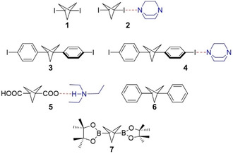
BCP Scaffolds used in current study.
Results and Discussion
X‐ray Analysis
A combination of halogen and hydrogen bonds is a versatile tool in supramolecular chemistry. [15a] Keeping this concept in mind, we decided to start our investigation from 1,3‐bisiodobicyclo[1.1.1]pentane (1). BCP 1 was crystallized via the slow evaporation of a DCM solution at room temperature. The collected data set indicated a monoclinic unit cell, and a solution to the data set was found in the P21/c space group. Figure 2a shows one complete molecule in the asymmetric unit. Bond lengths and bond angles are within the expected range for BCP derivatives, [15b] highlighting the rigidity of the linker. No significant intermolecular interaction or halogen bonding was observed in the crystal packing for BCP 1, the absence of NCI interaction demonstrates the limited acidity of the BCP skeleton.
Figure 2.
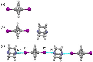
(a) View of the molecular structure of BCP 1 in the asymmetric unit. (b) Molecular structure of BCP 2. (c) Molecular arrangement of BCP 2 in crystal packing shows one‐dimensional halogen bond pattern.
DABCO is often used as a base in organic synthesis [16] and is a useful synthon for supramolecular architectures. [17] DABCO forms strong halogen bonds as compared to other neutral bases, owing to the rigid pyramidal shape around the N‐atom. Due to its strong electron‐donating properties, we decided to co‐crystallize 1+DABCO (2). In a reaction between BCP 1 and DABCO, the reactants were ground in an agate mortar for ca. 15 min. White co‐crystals of (2) in a 1 : 1 ratio were obtained by slow evaporation of a CHCl3 solution containing a crushed mixture of BCP 1 and DABCO in a 1 : 1 molar ratio at room temperature. We tried different molar ratios of constituent compounds; however, in each case, the 1 : 1 stoichiometry was observed. Hence, the stoichiometry was not affected by the molar ratio of the BCP 1 and DABCO. Compound 2 crystallized in the monoclinic lattice system in the P21/m space group. As expected, co‐crystal 2 featured short contacts between the N‐atom of DABCO and the iodine atom of BCP (Figure 2). The I2 ⋅⋅⋅ N1 distance was found to be 3.040(5) Å at the angle of 177.68(15)°; however, the I1 ⋅⋅⋅ N2 distance was 3.072(6) Å at the angle of 179.74(15)°. The observed X‐bond lengths and angles suggest that these interactions are subjected to type I (close packing interactions). [18]
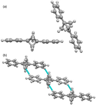
1,4‐Diiodobenzene has been established as a reliable component for the rational synthesis of halogen bond‐based assemblies. Considering the σ‐hole features of Ar−I, we decided to crystallize and investigate the non‐covalent interactions (NCI) in 1,3‐bis(4‐iodophenyl)bicyclo[1.1.1]pentane (3). X‐ray quality single crystals of compound 3 were obtained by slow evaporation of a CDCl3 solution at room temperature. The collected data set indicated a monoclinic unit cell, and a solution to the data set was found in the P21/n space group. In this crystal structure, the two aryl rings on opposite sides of the BCP unit are inclined at 59.38°, highlighting the combination of conformational rigidity and rotational flexibility offered by this linker. In contrast to 1, the crystal structure of BCP scaffold 3 demonstrates standard ‘type I’ I ⋅⋅⋅ I interaction, at 3.677(6) Å (Figure 3), possibly owing to the greater polarization of the C−I bond.
Figure 3.
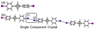
(a) View of the molecular structure of BCP 3 in the asymmetric unit. (b) The molecular arrangement of BCP 3 in crystal packing shows one‐dimensional halogen bond pattern.
The BCP cocrystal 4 was afforded by grinding BCP 3 and DABCO in an agate mortar and pestle. The light pink colored crystals of 4 were obtained by slow evaporation of a CHCl3 solution containing 1 : 1 crushed mixture of BCP 3 and DABCO at room temperature. The asymmetric unit of co‐crystals of BCP 4 contains two molecules of 3 and one molecule of DABCO. The co‐crystallization attempts were performed with the different molar ratios of BCP 3 and DABCO; however, in each case, we observed a 2 : 1 ratio of BCP 3 and DABCO (Figure 4a). The crystal structure of 4 exhibited a one‐dimensional linear chain of I ⋅⋅⋅ I (3.716(8) Å, 160.30(2)° C−I ⋅⋅⋅ I) and I ⋅⋅⋅ N (2.878(4) Å, 166.8(10)° C−I ⋅⋅⋅ N) interactions, indicative ‘type I’ halogen bonding. The angle between aryl rings in the DABCO adduct (49.55°) again highlights the rotational flexibility of the BCP. It was observed that the formation of I ⋅⋅⋅ I or I ⋅⋅⋅ N depends upon the relative orientation of 4‐iodophenyl rings. As shown in Figure 4b, the iodo moiety in ring A which is twisted more from the BCP skeleton showed a preference for I ⋅⋅⋅ I interaction whereas the less twisted ring B exhibited I ⋅⋅⋅ N interaction.
Figure 4.
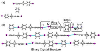
(a) View of the molecular structure of BCP 4 in the asymmetric unit. (b) The molecular arrangement of BCP 4 in crystal packing shows a halogen bond pattern.
We applied a systematic approach for BCP 1–4 to study the non‐bonded intermolecular interactions. Table 1 depicted the comparative analysis of the halogen bond (XB) in BCP 1–4. Table 1 reveals that the electronic nature of the BCP scaffold is highly dependent upon the bridgehead substituents. Surprisingly, BCP 1 did not show any halogen bonding in the crystal; however, the addition of DABCO activated the halogen bond interactions in BCP 2. In a similar vein, the type of halogen bond strictly depends upon the angle between the aromatic units. As seen in BCP 3 and 4, there is a relationship between the halogen bond and the co‐planar alignment of the phenyl rings (Table 1).
Table 1.
Comparative analysis of halogen bonds in BCP scaffolds (1–4).
|
BCP |
D(I ⋅⋅⋅ I) [Å] |
D(I ⋅⋅⋅ N) [Å] |
∠(C−I ⋅⋅⋅ I) [°] |
∠(C−I ⋅⋅⋅ N) [°] |
[%] sum of vdW[a] |
|---|---|---|---|---|---|
|
1 |
n/a |
n/a |
n/a |
n/a |
n/a |
|
2 |
n/a |
3.040(5); 3.072(6) |
n/a |
177.68(15); 179.74(15) |
∼86 %; ∼87 % |
|
3 |
3.677(6) |
n/a |
163.68(17) |
n/a |
∼93 % |
|
4 |
3.716(8) |
2.878(4) |
160.30(2) |
166.0(10) |
∼93 % for I ⋅⋅⋅ I; ∼82 % for I ⋅⋅⋅ N |
[a] vdW refer to van der Waals radii.
In order to gain more insight into the non‐covalent interactions of the BCP, it was hypothesized that charge and hydrogen bonding may have a significant interplay. Carboxylic acids are one of the most exploited species for hydrogen bond interactions [18a] and BCP‐1,3‐dicarboxylic acid readily available. [18b] Initial attempts to crystallize BCP‐1,3‐dicarboxylic acid were unsuccessful, as were co‐crystallization attempts with BCP‐1,3‐dicaboxylic acid and DABCO. When a significant excess of Et3N was employed to deprotonate the carboxylic acid, colorless crystals of 5 were apparent on evaporation of an acetonitrile solution to dryness over 72 hours. Structure 5 crystallized in the monoclinic space group C2/c. The co‐crystal of BCP‐1,3‐dicarboxylic acid with Et3N exhibited a surprising ratio of 1 : 1 Et3N:BCP and only partial deprotonation of the dicarboxylic acid, previously observed for 2,3,5,6‐tetrafluoroterephthalic acid and its anionic form. [19] Three different molecules i. e. BCP acid, BCP dianion, and Et3NH were present in one asymmetric unit (Figure 5a).
Figure 5.
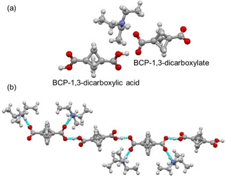
(a) View of the structure of 5 in the asymmetric unit. (b) Hydrogen bond and packing pattern in 5.
The structure forms a one‐dimensional hydrogen‐bonded chain of BCP diacid and the corresponding dianion, along the crystallographic 2a+c direction. The hydrogen atoms refined to an O−H distance of 1.064(16) Å, with an intermolecular H1 ⋅⋅⋅ O1 distance of 1.431(16) Å; the O ⋅⋅⋅ O contact of 2.4928(12) Å and angle of 174.5(14)°, indicating an exceptionally energetically favorable interaction, fitting the definition of a low‐barrier hydrogen bond. [20] Additional hydrogen bonding is observed between the triethylammonium cation and the BCP dianion, a strong interaction N−H ⋅⋅⋅ O (2.6731(13) Å D ⋅⋅⋅ A) and weaker charge‐assisted C−H ⋅⋅⋅ O interaction (3.110 Å D ⋅⋅⋅ A) (Figure 5b). Despite a charge difference between the anion and acid molecules, the bridgehead transannular distances are approximately equal (1.873(2) Å (C1−C1’) vs 1.874(2) Å (C7−C7′).
The importance of −COOH, −COOCH3, and −COONH2 functional groups in H‐bonding are well demonstrated both experimentally and theoretically. Boronic acid and ester exhibit a similar potential for H‐bond formation; however, these entities are less explored in terms of supramolecular assemblies. [21] For the BCP 6, X‐ray quality crystals were obtained by slow evaporation of a DCM solution at room temperature, and the compound crystallized in a tetragonal unit cell space group P‐421 c. In this structure, one molecule of 6 sits at the center of the unit cell, and another symmetry‐related molecule at the origin; 12 partially occupied carbon atoms and their methylene hydrogens comprise the BCP bridge – all other components are ordered. As can be seen in Figure 6, the electron density associated with the BCP unit is essentially completely rotationally averaged. The pinacolborane unit shows the bond distances and conformation expected for this substructure and only facile supramolecular interactions. As a consequence of the crystalline symmetry, the two pinacolborane groups sit at right angles to one another.
Figure 6.
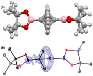
(a) Molecular structure of BCP 6 in the asymmetric unit. (b) electron density (Fobs, blue, 1.5 e−Å−3) showing the rotational averaging of the electron density associated with bridging carbon atoms.
In the crystal lattice of BCP 6, the (CH3)4C2O2B moieties were held together by O1 ⋅⋅⋅ H1 interactions, resulting in a 3D‐architecture. These interactions were observed at 2.620(5) Å with an angle of 147.4(6)° (Figure 7). It is worth noting that there is a relationship between the alignment of pinacolborane units and O1 ⋅⋅⋅ H1.
Figure 7.
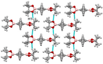
O1 ⋅⋅⋅ H1 interactions in the crystal packing of BCP 6.
In each of the aforementioned BCP crystal structures described, the formation of specific interactions was designed for by incorporation of a specific chemical motif. The diphenyl‐BCP can be considered as a standard scaffold, without any specific binding motifs. Moreover, weak non‐covalent interactions including cation ⋅⋅⋅ π, anion ⋅⋅⋅ π, π ⋅⋅⋅ π, CH ⋅⋅⋅ π play an important role in controlling supramolecular structure and function. Hence, for comparative analysis, the H ⋅⋅⋅ H and/or C ⋅⋅⋅ H interactions in BCP 7 were analyzed (Figure 8).
Figure 8.
(a) View of the molecular structure of BCP 6 in the asymmetric unit. (b) The organization of BCP 6 in crystal packing shows CHBCP ⋅⋅⋅ HPh interactions and packing pattern.
X‐ray quality crystal of BCP 7 was grown by slow evaporation of the solution in hexane at room temperature and the compound crystallized in the monoclinic space group P21/c, with two halves of two crystallographically distinct molecules in the asymmetric unit, each situated over a crystallographic inversion. The BCP cores, with an approximate three‐fold axis, are thus disordered over two orientations, and the phenyl rings in these molecules are coplanar (Figure 8a). The bond distances and orientations of these molecules were within error margins of one another, and BCP transannular distances of 1.891(4) Å and 1.886(5) Å are as expected. The structure of BCP 6 lacks any π ⋅⋅⋅ π stacking because of the steric bulk of the BCP skeleton. Remarkably, we observed the activation of the H2CBCP carbon towards non‐covalent interactions. The CBCP ⋅⋅⋅ H−CPh interaction was observed at 2.694 Å (∼93 % of vdW) with an angle of 156.8(8)°. The interaction is directive and led to the formation of a non‐covalently linked BCP assembly (Figure 8b). Additional illustrations for the single‐crystal X‐ray structures 1–7 are given in Figure S1–S7 in the supporting information (SI).
As before, we observed that the transannular distance for BCP 1–7 depends on the nature of bridgehead substitution (Table S1 in SI). BCP 1 exhibited the smallest transannular distance (1.804(8) Å) whereas; BCP 6 has shown the largest distance (1.923(3) Å) between the bridgehead carbons. Having established interesting structural aspects in BCP derivatives it is necessary to quantify the percentage and strength of the observed non‐bonded interatomic contacts. Hence, in the next section, our objective is to cast more light on the non‐covalent contacts with the use of Hirshfeld analysis.
Hirshfeld Surface Analysis
The Hirshfeld surfaces (dnorm) and corresponding 2D fingerprint plots were calculated to quantify the potential non‐covalent interactions present in BCP scaffolds 1–7. The Hirshfeld surface represents the region in three dimensions where molecules interact with each other. The normalized functions of di (x‐axis) and de (y‐axis) are used in dnorm plotting. The surfaces show red, blue, and white colors, white surface illustrate contacts with a sum equal to van der Waals radii (vdW), red indicate contacts with sum shorter than van der Waals radii (vdW), blue surface depicted the longer contacts. [22]
As described in X‐ray analysis, BCP 1 does not show any significant non‐covalent interactions on the Hirshfeld surface within the given range of van der Waals radii. Figure 9 represents the Hirshfeld surfaces and corresponding fingerprint region for the cocrystal 2. The I ⋅⋅⋅ N interactions appear as the largest interaction on fingerprint plot, concentrated in the middle, having de+di≃3.0 Å, with an overall contribution of the 47 % of fingerprint region.
Figure 9.
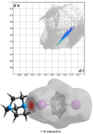
Fingerprint plot with I ⋅⋅⋅ N interactions highlighted and corresponding dnorm surface for 2.
Subsequently, we analyzed the Hirshfeld surfaces of BCP scaffold 3 (Figure S8 in SI). The two‐dimensional fingerprint plots show that H ⋅⋅⋅ H interactions were prominent with 34.5 % of fingerprint region, having de=di≃1.2 Å. The C ⋅⋅⋅ H/H ⋅⋅⋅ C interaction appeared as the second largest region with 30.4 % of the fingerprint plot with de+di≃2.8 Å. The participation of BCP bridge H‐atoms in the H ⋅⋅⋅ H interactions indicated that the insertion of two phenyl rings stimulated the BCP bridge H‐atom to take part in non‐covalent interactions. In contrast to H ⋅⋅⋅ H interactions, only the phenyl ring took part in the C ⋅⋅⋅ H interactions. The H ⋅⋅⋅ I interactions were highly concentrated at the edges, which contribute 32 % of the Hirshfeld surface with de+di≃3.1 Å. The dnorm surface for H ⋅⋅⋅ I interaction depicted that these interactions were highly concentrated on the I‐atoms and BCP skeleton. The I ⋅⋅⋅ I interaction was appeared as a red spot and covered only 3.0 % but are significant (Sharp blue‐green spike in fingerprint plot).
Hirshfeld surface analysis of 4 illustrated that H ⋅⋅⋅ H contacts make up 44.3 % of the surface. The proportion of the H ⋅⋅⋅ H interactions increased compared to BCP 3, potentially due to the presence of a DABCO unit between two BCP units. Similar to 3, the C ⋅⋅⋅ H/H ⋅⋅⋅ C was the second prominent interaction; however, the percentage of the surface is smaller as compared to the monomer unit. As expected, I ⋅⋅⋅ I and I ⋅⋅⋅ N halogen interactions were quite significant on the surface, appeared as bright red spots on dnorm surface, having de+di≃2.9 Å. Although the percentage of the I ⋅⋅⋅ N is low the short distance shows these interactions are quite strong (sharp blue‐green spike in fingerprint plot; Figure S9 in SI).
The influence of anionic and neutral forms on the Hirshfeld surface is one of the interesting aspects of the current study. BCP 5 is present as a model compound for this purpose since it incorporates a dianionic form of BCP (denoted as 5A) and a neutral BCP unit (denoted as 5B). Significant intermolecular interactions were observed in 5 and mapped in Figure 10. The respective donor and acceptor atoms show strong intermolecular hydrogen bonds, indicated as a bright red spot on the dnorm surfaces and bright green spikes in fingerprint plots. Two sharp spikes were observed for the O ⋅⋅⋅ H/H ⋅⋅⋅ O contact corresponding to the C−O ⋅⋅⋅ H and N−H ⋅⋅⋅ O interactions. Hirshfeld surface of BCP 5 A featured predominantly HB character (49.9 % of total surface), which is a potential consequence of its dianionic nature (Figure 10b). It was also detected that H ⋅⋅⋅ H contacts covered the second‐largest share of the surface (43 % of total surface) with de=di≃1.2 Å. As stated in the X‐ray section, C ⋅⋅⋅ H contacts covered 6.3 % of the surface at the distance of de+di<2.9 Å.
Figure 10.
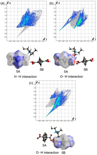
(a) Fingerprint plot with H ⋅⋅⋅ H interactions highlighted and corresponding dnorm surface for the BCP 5A. (b) Fingerprint plot with O ⋅⋅⋅ H interactions highlighted and corresponding dnorm surface for the BCP 5A. (c) Fingerprint plot with H ⋅⋅⋅ H interactions highlighted and corresponding dnorm surface for BCP 5B.
Next, we observed how the Hirshfeld surface properties of the neutral BCP acid 5B are different from the 5A. The difference is mainly reflected in the total share of H‐bond contacts, C ⋅⋅⋅ H, and H ⋅⋅⋅ H interactions. The O ⋅⋅⋅ H/H ⋅⋅⋅ O contact was predominant and cover the ∼43 % area of the fingerprint region (Figure 10c). Similar to BCP 5A the H‐bond is short and in accordance with reports available in the literature. [20] Surprisingly, only weak H ⋅⋅⋅ H and C ⋅⋅⋅ H contacts were observed for the given molecules. Although contacts appeared as the second‐largest contributor in the 2D fingerprint region; however, the observed distance was slightly higher than van der Waals radii.
To quantify the intermolecular contacts in BCP 6, we analyzed the fingerprint plots and dnorm surfaces. Figure S10 (SI) represents the semitransparent dnorm‐mapped Hishfeld surface for BCP scaffold 6. As expected, a significant share of the total region corresponds to H ⋅⋅⋅ H contacts at the distance of de=di≃1.2 Å. The H ⋅⋅⋅ H interaction appeared in most of the fingerprint region (∼83 % of the total surface), potentially due to rotational disordered present in the BCP skeleton. Additionally, the observed H ⋅⋅⋅ H contacts are quite strong and mapped as a bright green color in the fingerprint plot. The other significant contact observed for the BCP 6 were O ⋅⋅⋅ H interactions, which covered ∼16 % of the total surface area. These contacts were quite important, appeared as a red spot on dnorm surface. Although this interaction did not cover a large portion of the Hirshfeld surface it controls the three‐dimensional alignment of the molecules.
Lastly, BCP 7 is a classic example of a rigid hydrocarbon scaffold. The H ⋅⋅⋅ H contacts are able to influence the three‐dimensional arrangement of the molecules and appeared as the structure directive motif (Figure S11 in SI).
The findings from the Hirshfeld analysis indicate the significance of non‐covalent interactions in the crystal packing of the BCP units. In the next step, we optimized the structures using DFT calculations to investigate the electronic nature of the interactions observed from the crystallographic analysis.
Theoretical Calculations
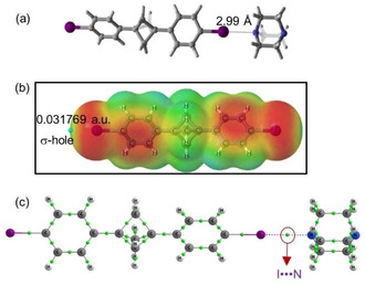
DFT calculations were performed to characterize the different non‐covalent interactions (HB and XB bonding) discussed in the description of the crystal structures and Hirshfeld surface analysis (HSA). To determine the charge distribution and to elucidate the halogen‐bond donor and accepting ability, the molecular electrostatic potentials (MEP) of BCP scaffolds 1–4 were calculated. [22] The optimized geometry corresponding to assembly 2 is depicted in Figure 11a, showing a I ⋅⋅⋅ N distance of 2.99 Å. The observed halogen bond distance is in close agreement with the experimental values (vide supra).
Figure 11.
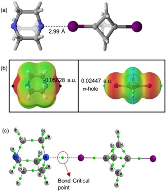
(a) Optimized structure of BCP 2. (b) Molecular electrostatic potential on the 0.001 a.u electron density isosurface for DABCO and 1,3‐bisiodo‐BCP. (c) Atom‐in‐molecule calculation (AIM) graph for assembly 2, green dots indicating the bond critical points.
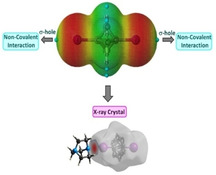
MEP analysis was performed for BCP 2 to analyze the electron‐rich and electron‐poor region in the molecules. The MEP map for DABCO indicated the red region on either side of the molecule (negative MEP), corresponding to the lone pair on the nitrogen atoms. In the case of diiodoBCP, an electron‐deficient region on the outermost portion of the halogen's surface cantered on the R−I axis of the BCP 1, corresponding to the σ‐hole was observed (Figure 11b).
In order to characterize the nature of the intermolecular interaction established Atoms in Molecules (QTAIM) analysis was carried out. [23] This approach has been widely employed for different non‐covalent interactions. From the molecular graph of scaffold 2 (Figure 11c) and the analysis of the density at the bond critical point found between both atoms involved, it can be demonstrated the existence of a halogen bond between I and N atoms. The values of the electron density at the bond critical point, ρ(BCP), (0.0207) and Laplacian, ∇2ρ(BCP), of the electron density (0.0560) at the bond critical point are given in Table S4 (SI) and indicated the closed‐shell feature of the halogen bond established between BCP and DABCO.
As previously stated, the asymmetric unit of the crystal structure of BCP 3 contains two crystallographically distinct molecules. Hence, two different optimized structures were obtained for BCP 3, from two distinct starting orientations. In the first, two molecules of BCP 3 were placed in a perpendicular configuration; from the analysis of the QTAIM molecular graph, this configuration exhibited I ⋅⋅⋅ I, and H ⋅⋅⋅ I interactions; however, the energetically minimized bond length, as well as the value of the density at the involved bond critical points found for I ⋅⋅⋅ I interaction, indicated only weak interaction beyond the sum of van der Waals radii (Figure S12a in SI). When two BCP units were placed almost parallel to each other, the QTAIM analysis of the energy‐minimized complex indicated the presence of I ⋅⋅⋅ CH, I−C ⋅⋅⋅ CH, and π ⋅⋅⋅ π interactions (Figure S12b in SI). Importantly, it was observed that interactions in the parallel configuration (ΔEint=−15.5 kcal/mol) were stronger as compared to the perpendicular one (ΔEint=−2.5 kcal/mol).
Next, the interaction energies between two molecules of BCP 3 from the crystal structure were calculated (without optimization; Figure S13 in SI). The observed interaction profile is quite similar to the optimized structure in the parallel form, indicating the presence of I ⋅⋅⋅ CH, I−C ⋅⋅⋅ CH, and π ⋅⋅⋅ π interactions. The calculated H ⋅⋅⋅ I bond length (3.18 Å) is in good agreement with the experimental values (3.17 Å). Furthermore, the small value of electron density and positive Laplacian of electron density revealed the characteristic features of weak non‐covalent interactions (Table S4 and S5 in SI). Moreover, the interaction energy was also comparable to the parallel configuration (−13.4 kcal/mol vs. −15.5 kcal/mol). The results obtained from DFT analysis indicated the I ⋅⋅⋅ I interaction observed in the X‐ray structure was a potential consequence of closed packing of molecules in crystal structure whereas in the gas phase H ⋅⋅⋅ I, CH ⋅⋅⋅ π, and π ⋅⋅⋅ π interactions were preferred.
Figure 12a shows the optimized structure of the binary complex 4, indicating the presence of a halogen bond between the I‐atom of iodophenyl ring and the N‐atom of DABCO. The theoretical I ⋅⋅⋅ N bond length is shorter than the sum of the corresponding atomic van der Waals radii (RI ⋅⋅⋅ N=3.53 Å). The molecular electrostatic potential map shows the two green regions at the iodine terminus, indicating the presence of a σ‐hole from the C−I bond, the principal consideration for halogen bonding. It is worth noting that the MEP values are more positive as compared to BCP 1 (Figure 12b). The interaction energy for this BCP scaffold 4 (ΔEint=−6.7 kcal/mol) is slightly higher as compared to BCP 2 (ΔEint=−6.3 kcal/mol), therefore, the halogen bond is comparatively stronger. Figure 12c shows the AIM graph for BCP 4, indicating bond critical points and bond path for I ⋅⋅⋅ N interactions. Although the density at bond critical point and Laplacian of electron density values for 4 are comparable with the values for 2 (0.0213 and 0.0580 v.s 0.0207 and 0.0560) the more positive σ‐holes at Ph−I indicate the existence of stronger I ⋅⋅⋅ N interaction for the BCP 4 (Figure 12b).
Figure 12.
(a) Optimized structure of assembly 4. (b) Molecular electrostatic potential on the 0.001 a.u electron density for BCP 3. (c) Atom‐in‐molecule calculation (AIM) graph for BCP 4, green balls indicating the bond critical points.
When complex 5 was studied a very different situation appeared. Since both moieties are charged and the calculations were performed in the gas phase, the proton from the nitrogen atom of the base moved towards the negatively charged oxygen of the carboxylate moiety to compensate the charges, and therefore a very strong N ⋅⋅⋅ H ⋅⋅⋅ O interaction between trimethylamine and BCP 1,3‐dicarboxylate was observed. To avoid this issue and therefore reproduce the interactions found in the crystal structure, a new optimization was performed in which the distance NH ⋅⋅⋅ O was fixed at 1.77 Å (crystal distance) and the rest of the complex was optimized. The calculated interaction energy was significantly higher (−246.7 kcal/mol) for this complexation because of the charged atoms. As shown in Figure 13, bond critical points and bond paths were observed for the NH ⋅⋅⋅ O and CH ⋅⋅⋅ O contacts. The high‐density value exhibit at the bond critical points demonstrated that the hydrogen bonds established are, as expected, very strong.
Figure 13.
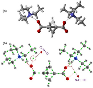
(a) Optimized structure for BCP‐1,3‐dicarboxylate and triethylamine. (b) Atom‐in‐molecule calculation (AIM) graph for corresponding structure, green dots indicating the bond critical points.
In a similar vein, BCP 6 was optimized in the gas phase. The optimized structure showed two types of interatomic non‐bonded contacts, first the head‐to‐tail O ⋅⋅⋅ H interaction at the distance of 2.65 Å, and second a weaker C ⋅⋅⋅ H at the distance of 3.17 Å. The observed interactions are in good agreement with the experimental values. The interaction energy for this compound was found to be −7.4 kcal/mol (Table S4 in SI). Figure 14 shows the optimized structure and AIM graph for BCP 6.
Figure 14.
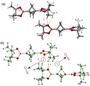
(a) Optimized structure for BCP 6. (b) Atom‐in‐molecule calculation (AIM) graph for BCP 6, green dots indicating the bond critical points.
Conclusion
In summary, we presented the first systematic study on the non‐covalent interactions of BCP derivatives. The BCP scaffold is rigid but does not allow for the same bond polarization as an aryl unit. The BCP unit is often disordered, and sits across highly symmetric sites, consistent with the observation that it forms very weak interactions in the solid‐state. Transannular distances are varied by substituents on the BCP 1,3‐positions but generally retains D3h symmetry.
Co‐crystals of 1 and 3 with DABCO show charge transfer and prominent halogen bonding. Hirshfeld surface analysis, molecular electrostatic potentials, and topological analysis (atoms‐in‐molecules) were carried out to quantify the strength of all non‐covalent interactions in co‐crystals. These investigations revealed that halogen bond interactions (I ⋅⋅⋅ N and I ⋅⋅⋅ I) were more dominant in BCP scaffolds 2–4. Furthermore, short O ⋅⋅⋅ H contacts were observed for the BCP‐1,3‐dicarboxylic acid and BCP‐1,3‐dicarboxylate in 5. BCP 6 also exhibited intermolecular short O ⋅⋅⋅ H contacts. In the end, BCP 7 shows selective and directive intermolecular C ⋅⋅⋅ H contacts.
These trends indicate that activation of the non‐covalent interactions can serve as an effective design principle in directing short contacts, and therefore the electronic and structural properties of scaffolds. DFT analysis for BCP 2 and 4 supported the structural results; however, I ⋅⋅⋅ I interactions in BCP 3 are a result of close packing in the crystal structure. Similarly, the optimized structure for BCP‐1,3‐dicarboxylate and triethylamine shows a strong NH ⋅⋅⋅ O contact which is in close agreement with the structural results. The findings observed in the present work might be successfully applied to the synthesis of BCP‐based bioisosteres that exhibit the three‐dimensional saturated core whilst simultaneously providing bridgehead functionalities for molecular recognition.
Experimental Section
X‐ray Crystallography
Crystals were grown following the protocol developed by Hope. Compounds were dissolved in either DCM, hexane, or CDCl3 and allowing for slow evaporation over time. [24] Single crystal X‐ray diffraction data for all compounds were collected on a Bruker APEX 2 DUO CCD diffractometer by using graphite‐monochromated Mo Kα (λ=0.71073 Å) radiation and Incoatec IμS Cu Kα (λ=1.54178 Å) radiation. Crystals were mounted on a MiTeGen MicroMount and collected at 100(2) K by using an Oxford Cryosystems Cobra low‐temperature device. Data were collected by using omega and phi scans and were corrected for Lorentz and polarization effects by using the APEX software suite. [25] Using Olex2, the structure was solved with the XT structure solution program, using the intrinsic phasing solution method and refined against|F2| with XL using least‐squares minimization. [26] Hydrogen atoms were generally placed in geometrically calculated positions and refined using a riding model. Details of data refinements can be found in Tables S4 and S5 in SI. All images were prepared by using Olex2 [25a] and Mercury. [27] A detailed discussion on data refinement and modeling is described in section 2 in SI.
Deposition Numbers 2042456 (for 3), 2042457 (for 6), 2042458 (for 7), 2042459 (for 5), 2042460 (for 2), 2042461 (for 4), 2042462 (for 1) contain the supplementary crystallographic data for this paper. These data are provided free of charge by the joint Cambridge Crystallographic Data Centre and Fachinformationszentrum Karlsruhe Access Structures service www.ccdc.cam.ac.uk/structures.
Hirshfeld Surface Analysis
The two‐dimensional fingerprint plots and associated Hirshfeld surfaces [13] were calculated using CrystalExplorer. [28] The intermolecular contacts in crystal packing were visualized using dnorm surface. The di (outside) and de (outside) represent the distance to the Hirshfeld surface from nuclei. The proportional contribution of the contacts over the surface is visualized by the color gradient (blue to green) in the fingerprint plots.
Computational Methods
The structures of the complexes were optimized at wb97xd/6‐311++g(d,p) computational level. [29] Harmonic vibrational frequencies were computed at the same level used for the geometry optimizations in order to confirm that the stationary points are local minima. For the heavy atom I, the def2tzvp pseudopotential [30] was used to incorporate relativistic effects. Calculations were performed using the Gaussian16 software. [31] Interaction energies (ΔEint) were calculated as a difference of the energy of the optimized complex minus the energy of each monomer in their optimized geometry. The molecular electrostatic potential (MEP) of the isolated monomers was calculated on the electron density isosurface of 0.001 au. This isosurface has been shown to resemble the van der Waals surface. [32] These calculations were numerical results analyzed using the Multiwfn and plotted using Jmol carried out with the Gaussian‐16 software. [33] The Atoms in Molecules (AIM) methodology was used to analyze the electron density of the systems with the AIMAll program. [34] The Natural Bond Orbital (NBO) [35] method was employed to evaluate atomic charges using the NBO‐3 program and to analyze charge‐transfer interactions between occupied and unoccupied orbitals.
Conflict of interest
The authors declare no conflict of interest.
Supporting information
As a service to our authors and readers, this journal provides supporting information supplied by the authors. Such materials are peer reviewed and may be re‐organized for online delivery, but are not copy‐edited or typeset. Technical support issues arising from supporting information (other than missing files) should be addressed to the authors.
Supplementary
Acknowledgements
This work was supported by grants from Science Foundation Ireland (SFI, IvP 13/IA/1894 and (SFI 18/SIRG/5517), and the European Union's Horizon 2020 research and innovation program under the FET Open grant agreement No. 828779. The manuscript was prepared with the support of the Technical University of Munich – Institute for Advanced Study through a Hans Fischer Senior Fellowship. Open access funding enabled and organized by Projekt DEAL.
N. Grover, K. J. Flanagan, C. Trujillo, C. J. Kingsbury, M. O. Senge, Eur. J. Org. Chem. 2021, 2021, 1113.
In memoriam Prof. Marilyn M. Olmstead.
Contributor Information
Dr. Nitika Grover, http://trujilloresearchgroup.com/.
Dr. Cristina Trujillo, Email: trujillc@tcd.ie.
Prof. Dr. Mathias O. Senge, Email: sengem@tcd.ie, https://chemistry.tcd.ie/staff/people/mos/Home.html, https://www.ias.tum.de/active‐fellows/senge‐mathias/.
References
- 1.
- 1a. Desiraju G. R., Crystal Engineering. The Design of Organic Solids, Elsevier, Amsterdam, 1989; [Google Scholar]
- 1b. Crystal Design. Structure and Function. Perspectives in Supramolecular Chemistry (Ed.: G. R. Desiraju), Wiley, Chichester, 2003;
- 1c. Frontiers in Crystal Engineering (Eds.: E. R. Tiekink, J. J. Vittal), Wiley, Chichester, 2005.
- 2. Saha S., Mishra M. K., Reddy C. M., Desiraju G. R., Acc. Chem. Res. 2018, 51, 2957–2967. [DOI] [PubMed] [Google Scholar]
- 3.
- 3a. Berger G., Frangvillea P., Meyer F., Chem. Commun. 2020, 56, 4970–4981; [DOI] [PubMed] [Google Scholar]
- 3b. Chen L.-J., Yang H.-B., Acc. Chem. Res. 2018, 51, 2699–2710. [DOI] [PubMed] [Google Scholar]
- 4.
- 4a. Kollman P. A., Allen L. C., Chem. Rev. 1972, 72, 283–303; [Google Scholar]
- 4b. Mukherjee A., Tothadi S., Desiraju G. R., Acc. Chem. Res. 2014, 47, 2514–2524; [DOI] [PubMed] [Google Scholar]
- 4c. Nishio M., Hirota M., Umezawa Y., The CH/π Interaction; Wiley-VCH: New York, 1998; [Google Scholar]
- 4d. Thakuria R., Nath N. K., Saha B. K., Cryst. Growth Des. 2019, 19, 523–528; [Google Scholar]
- 4e. Meyer E. E., Rosenberg K. J., Israelachvili J., Proc. Natl. Acad. Sci. USA 2006, 103, 15739–15746. [DOI] [PMC free article] [PubMed] [Google Scholar]
- 5. Bissantz C., Kuhn B., Stahl M., J. Med. Chem. 2010, 53, 5061–5084. [DOI] [PMC free article] [PubMed] [Google Scholar]
- 6. Veber D. F., Johnson S. R., Cheng H.-Y., Smith B. R., Ward K. W., Kopple K. D., J. Med. Chem. 2002, 45, 2615–2623. [DOI] [PubMed] [Google Scholar]
- 7.
- 7a. Lovering F., Bikker J., Humblet C., J. Med. Chem. 2009, 52, 6752–6756; [DOI] [PubMed] [Google Scholar]
- 7b. Lovering F., MedChemComm 2013, 4, 515–519; [Google Scholar]
- 7c. Square A., Abbott E. A., Flatland: A Romance of Many Dimensions, Seely, London, 1884. [Google Scholar]
- 8.
- 8a. Chalmers B. A., Xing H., Houston S., Clark C., Ghassabian S., Kuo A., Cao B., Reitsma A., Murray C.-E. P., Stok J. E., Boyle G. M., Pierce C. J., Littler S. W., Winkler D. A., Bernhardt P. V., Pasay C., DeVoss J. J., McCarthy J., Parsons P. G., Walter G. H., Smith M. T., Cooper H. M., Nilsson S. K., Tsanaktsidis J., Savage G. P., Williams C. M., Angew. Chem. Int. Ed. 2016, 55, 3580–3585; [DOI] [PubMed] [Google Scholar]
- 8b. Mykhailiuk P. K., Org. Biomol. Chem. 2019, 17, 2839–2849; [DOI] [PubMed] [Google Scholar]
- 8c. Locke G. M., Bernhard S. S. R., Senge M. O., Chem. Eur. J. 2019, 25, 4590–4647. [DOI] [PubMed] [Google Scholar]
- 9.
- 9a. Grover N., Senge M. O., Synthesis 2020, 52, 3295–3325; [Google Scholar]
- 9b. Ma X., Pham L. N., Asian J. Org. Chem. 2020, 9, 8–22. [Google Scholar]
- 10.
- 10a. Kaleta J., Michl J., Mézière C., Simonov S., Zorina L., Wzietek P., Rodríguez-Fortea A., Canadell E., Batail P., CrystEngComm 2015, 17, 7829–7834; [Google Scholar]
- 10b. Kaleta J., Nečas M., Mazal C., Eur. J. Org. Chem. 2012, 25, 4783–4796; [Google Scholar]
- 10c. Rodríguez-Fortea A., Kaleta J., Mézière C., Allain M., Canadell E., Wzietek P., Michl J., Batail P., ACS Omega 2018, 3, 1293–1297; [DOI] [PMC free article] [PubMed] [Google Scholar]
- 10d. Perego J., Bracco S., Negroni M., Bezuidenhout C. X., Prando G., Carretta P., Comotti A., Sozzani P., Nat. Chem. 2020, 12, 845–851; [DOI] [PubMed] [Google Scholar]
- 10e. Kuduva S. S., Craig D. C., Nangia A., Desiraju G. R., J. Am. Chem. Soc. 1999, 121, 1936–1944; [Google Scholar]
- 10f. Flanagan K. J., Bernhard S. S. R., Plunkett S., Senge M. O., Chem. Eur. J. 2019, 25, 6941–6954. [DOI] [PubMed] [Google Scholar]
- 11.
- 11a. Plunkett S., Flanagan K. J., Twamley B., Senge M. O., Organometallics 2015, 34, 1408–1414; [Google Scholar]
- 11b. Bernhard S. S. R., Locke G. M., Plunkett S., Meindl A., Flanagan K. J., Senge M. O., Chem. Eur. J. 2018, 24, 1026–1030; [DOI] [PubMed] [Google Scholar]
- 11c. Grover N., Locke G. M., Flanagan K. J., Beh M., Thompson A., Senge M. O., Chem. Eur. J. 2020, 26, 2405–2416; [DOI] [PMC free article] [PubMed] [Google Scholar]
- 11d. Sitte E., Twamley B., Grover N., Senge M. O., ChemRxiv 2020. 10.26434/chemrxiv.13076039.v1. [Google Scholar]
- 12. Almarsson Ö., Zaworotko M. J., Chem. Commun. 2004, 1889–2896. [DOI] [PubMed] [Google Scholar]
- 13.
- 13a. Hirshfeld F. L., Theor. Chim. Acta, 1977, 44, 129–138; [Google Scholar]
- 13b. Spackman M. A., Jayatilaka D., CrystEngComm 2009,11, 19–32. [Google Scholar]
- 14.
- 14a. Burns L. A., Vázquez-Mayagoitia Á., Sumpter B. G., Sherrill C. D., J. Chem. Phys. 2011, 134, 084107; [DOI] [PubMed] [Google Scholar]
- 14b. Alkorta I., Rozas I., Elguero J., Chem. Soc. Rev. 1998, 27, 163–170. [Google Scholar]
- 15.
- 15a. Saha B. K., Nangia A., Jaskólski M., CrystEngComm 2005, 7, 355–358; [Google Scholar]
- 15b. Irngartinger H., Reimann W., Garner P., Dowd P., J. Org. Chem. 1988, 53, 3046–3050. [Google Scholar]
- 16. Bita B., Eur. J. Chem. 2010, 1, 54–60. [Google Scholar]
- 17.
- 17a. Marivel S., Braga D., Grepioni F., Lampronti G. I., CrystEngComm 2010, 12, 2107–2112; [Google Scholar]
- 17b. Dabros M., Emery P. R., Thalladi V. R., Angew. Chem. Int. Ed. 2007, 46, 4132–4135; [DOI] [PubMed] [Google Scholar]
- 17c. Jiang X., Duan H.-B., Jellen M. J., Chen Y., Chung T. S., Liang Y., Garcia-Garibay M. A., J. Am. Chem. Soc. 2019, 141, 16802–16809. [DOI] [PubMed] [Google Scholar]
- 18.
- 18a. Cavallo G., Metrangolo P., Milani R., Pilati T., Priimagi A., Resnati G., Terraneo G., Chem. Rev. 2016, 116, 2478–2601; [DOI] [PMC free article] [PubMed] [Google Scholar]
- 18b. Kaszynski P., Michl J., J. Org. Chem. 1988, 53, 4593–4594. [Google Scholar]
- 19. Lackinger M., Heckl W. M., Langmuir 2009, 25, 11307–11321. [DOI] [PubMed] [Google Scholar]
- 20. Jin T., Zhang W., CrystEngComm 2019, 21, 4238–4242. [Google Scholar]
- 21. Hofmann D. W. M., Kuleshova L. N., Yu Antipin M., Cryst. Growth Des. 2007, 7, 1958–1963. [Google Scholar]
- 22. Murray J. S., Politzer P., WIREs Comput. Mol. Sci. 2011, 1, 153–163. [Google Scholar]
- 23. Bader R. F. W., Atoms in Molecules: A Quantum Theory, Clarendon Press, Oxford, 1990. [Google Scholar]
- 24.
- 24a. Hope H., Prog. Inorg. Chem. 1994, 41, 1–19; [Google Scholar]
- 24b. Senge M. O., Z. Naturforsch. 2000, 55b, 336–344. [Google Scholar]
- 25.
- 25a.Saint, Version 8.37a; Bruker AXS, Inc.: Madison, WI, 2013;
- 25b.SADABS, version 2016/2; Bruker AXS, Inc.: Madison, WI, 2014;
- 25c.APEX3, Version 2016.9-0; Bruker AXS, Inc.: Madison, WI, 2016.
- 26.
- 26a. Dolomanov O. V., Bourhis L. J., Gildea R. J., Howard J. A. K., Puschmann H., J. Appl. Crystallogr. 2009, 42, 339–341; [DOI] [PMC free article] [PubMed] [Google Scholar]
- 26b. Sheldrick G., Acta Crystallogr. 2015, A71, 3–8. [DOI] [PMC free article] [PubMed] [Google Scholar]
- 27. Macrae C. F., Bruno I. J., Chisholm J. A., Edgington P. R., McCabe P., Pidcock E., Rodriguez-Monge L., Taylor R., van de Streek J., Wood P. A., J. Appl. Crystallogr., 2008, 41, 466–470. [Google Scholar]
- 28. Turner M. J., McKinnon J. J., Wolff S. K., Grimwood D. J., Spackman P. R., Jayatilaka D., Spackman M. A., CrystalExplorer17, Version 17.5; University of Western Australia, 2017. [Google Scholar]
- 29.
- 29a. Chai J.-D., Head-Gordon M., Phys. Chem. Chem. Phys. 2008, 10, 6615–6620; [DOI] [PubMed] [Google Scholar]
- 29b. Frisch M. J., Pople J. A., Binkley J. S., J. Chem. Phys. 1984, 80, 3265–3269; [Google Scholar]
- 29c. Ditchfield R., Mol. Phys. 1974, 27, 789–807. [Google Scholar]
- 30. Schaefer A., Huber C., Ahlrichs R., J. Chem. Phys. 1994, 100, 5829–5835. [Google Scholar]
- 31.M. J. Frisch, G. W. Trucks, H. B. Schlegel, G. E. Scuseria, M. A. Robb, J. R. Cheeseman, G. Scalmani, V. Barone, G. A. Petersson, H. Nakatsuji, X. Li, M. Caricato, A. V. Marenich, J. Bloino, B. G. Janesko, R. Gomperts, B. Mennucci, H. P. Hratchian, J. V. Ortiz, A. F. Izmaylov, J. L. Sonnenberg, D. Williams Young, F. Ding, F. Lipparini, F. Egidi, J. Goings, B. Peng, A. Petrone, T. Henderson, D. Ranasinghe, V. G. Zakrzewski, J. Gao, N. Rega, G. Zheng, W. Liang, M. Hada, M. Ehara, K. Toyota, R. Fukuda, J. Hasegawa, M. Ishida, T. Nakajima, Y. Honda, O. Kitao, H. Nakai, T. Vreven, K. Throssell, J. Montgomery Jr, J. E. Peralta, F. Ogliaro, M. J. Bearpark, J. J. Heyd, E. N. Brothers, K. N. Kudin, V. N. Staroverov, T. A. Keith, R. Kobayashi, J. Normand, K. Raghavachari, A. P. Rendell, J. C. Burant, S. S. Iyengar, J. Tomasi, M. Cossi, J. M. Millam, M. Klene, C. Adamo, R. Cammi, J. W. Ochterski, R. L. Martin, K. Morokuma, O. Farkas, J. B. Foresman, D. J. Fox, Gaussian, Gaussian, Inc., Wallingford CT, 2016.
- 32. Bader R. F. W., Carroll M. T., Cheeseman J. R., Chang C., J. Am. Chem. Soc. 1987, 109, 7968–7979. [Google Scholar]
- 33.
- 33a. Lu T., Chen F., J. Comput. Chem. 2012, 33, 580–592; [DOI] [PubMed] [Google Scholar]
- 33b.Jmol: an open-source Java viewer for chemical structures in 3D, http://www.jmol.org/.
- 34.T. A. Keith, 2011, TK Gristmill Software, aim.tkgristmill.com.
- 35. Reed A. E., Curtiss L. A., Weinhold F., Chem. Rev. 1988, 88, 899–926. [Google Scholar]
Associated Data
This section collects any data citations, data availability statements, or supplementary materials included in this article.
Supplementary Materials
As a service to our authors and readers, this journal provides supporting information supplied by the authors. Such materials are peer reviewed and may be re‐organized for online delivery, but are not copy‐edited or typeset. Technical support issues arising from supporting information (other than missing files) should be addressed to the authors.
Supplementary