

Abstract
Hanging cell culture inserts are most widely used in vitro cell culture devices, which provide a freestanding multichamber setup for various co-culture and triculture systems. Apart from being costly, the commercial inserts do not provide enough choices regarding polymer types and pore sizes. Most importantly, commercially available inserts are two-dimensional multiporous membrane-based devices. Herein, we report a one-step fabrication process of the multifunctional nanofiber-based permeable hanging cell culture insert using electrospinning. These fabricated nanofibrous membranes’ attached inserts have advantages such as low cost, ready availability, easy fabrication, tunable porosity, autoclavability, and biomaterial-based nanofibrous membranes. The inserts without nanofibrous membrane can also be reused by autoclaving them and electrospun nanofibrous membrane on it according to the application. We have also confirmed its suitability for extensive use in the field of in vitro cell culture by analyzing its adherence and toxicity results on breast cancer cell line (MCF-7). These hanging cell culture inserts are thus a potent product for various cell culture assays such as cell migration for wound healing, cancer metastasis, and other tissue engineering applications.
1. Introduction
Hanging permeable inserts, also known as modified Boyden chambers, are widely used as in vitro cell culture devices in most of the cell culture laboratories around the globe. These permeable supports provide a freestanding multichambered arrangement in a regular 6, 12, 24, or 96 well tissue culture plate for studying various cellular metabolic activities such as transport of drugs, migration of cells, chemotaxis, etc., and most importantly for co-culture and triculture experiments. Commercially, a few companies manufacture two-dimensional (2D) multiporous permeable membrane-based cell culture inserts. These commercial cell culture inserts can broadly be differentiated based on their membrane-polymer types and membrane-pore sizes. Polyester or poly(ethylene terephthalate) (PET), polycarbonate (PC), and poly(tetrafluoroethylene) (PTFE) are the polymers used for the fabrication of such permeable membranes. These porous membranes have specific choosable pore sizes according to the use of cell types and applications, i.e., 0.4 μm for endothelial–epithelial cell co-culture studies; 5 μm for fibroblast, cancer, macrophages, and monocytes; 3 μm for leukocyte and lymphocyte; and 8 μm for epithelial and endothelial cells.1−5 However, without biological coatings, the inserts cannot completely mimic the three-dimensional (3D) microenvironment of the in vivo systems. They thus cannot provide the environment required for optimum cellular behavior in vitro.6−10 As a biological coating upon the membranes, companies generally prefer biomaterials like collagen, RGD (Arg-Gly-Asp) peptides to aid the adherence of the cells, but these coatings make the inserts more expensive. So, to avoid the addition of biological materials on the membrane, we fabricated one-step multifunctional porous nanofibrous scaffolds attached to inserts using biomaterials through a classical nanofiber fabrication technique known as electrospinning.
In electrospinning, a viscoelastic polymer is stretched using a very high voltage and collected as fibers (whose diameter falls in the nanometer to micrometer range) on a grounded metal collector.11 The nanofibrous mats mimic as an artificial extracellular matrix for adherence of cells and provide a 3D microenvironment similar to in vivo conditions. Nevertheless, using these nanofibrous scaffolds as a freestanding device has always been a challenge. One of the previous strategies used ring-type supports to hold the mechanically peeled nanofibrous mats from a grounded collector.12 Other plans included melting and attaching the nanofibrous membranes to the circumference of the insert bodies using a hot soldering rod13 or using a nickel mesh on the top of the insert bodies for directly fabricating the nanofibrous mat upon it.14 More recently, through electrolyte-assisted electrospinning (ELES), fiber fabrication was performed using electrolyte solution as a grounded collector, thus directly fabricating the fiber as a freestanding structure.15 One major drawback of these strategies is that the body of inserts is bought from the commercial distributors, which although are ready to use but expensive. In other cases, they used 3D-printed inserts, which again makes them costly and somewhat technologically challenging.
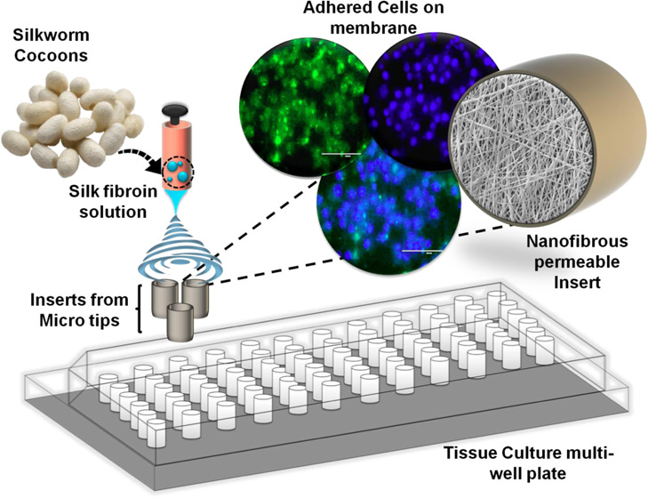
Our study reports the fabrication of insert’s body using readily available and low-cost materials. We have found that the 2–200 μL micropipette tips base fits perfectly into the 96 well tissue culture plates when it is cut at a certain length from the bottom. Therefore, we chose 2–200 μL micropipette tips and used its 1 cm base portion as a grounded collector for directly fabricating the nanofibrous scaffold through electrospinning. The hanging permeable insert so created is less expensive, easy to prepare, and can be used for a vast range of cell culture applications, such as wound healing, cancer metastasis, cell migration, chemotaxis, invasion assays, 3D tissue models, etc. The graphical illustration of the process of synthesizing the nanofiber-based hanging permeable cell culture inserts is represented in Figure 1.
Figure 1.

Graphical illustration of the process of synthesizing nanofiber-based hanging permeable cell culture inserts.
On the other hand, commercial sources mostly use synthetic polymers such as PC, PET, and PTFE, which have certain advantages like optical transparency and thermostability.16 However, these are plastic-based nonbiological polymers. The cellular attachment to the scaffolds depends not only on the pore sizes and the surface characteristics but also on the nature of the polymers used. The lack of bioactivity in synthetic polymers often results in problems associated with cell attachment and its behavior. Because of this reason, several recent investigations are centered around the use of different biological components as well as biomaterials for a myriad of different translational studies.17−20
Moreover, in various types of scaffold preparation, biological polymers like collagen, proteoglycan, alginate-based materials, chitosan, etc. have been found useful due to their excellent capability to promote cell adhesion, proliferation, cell function, and shape.13,14,19 Here, we have used silk fibroin (SF) as the biological polymer from Bombyx mori (Silkworm), having unique properties such as high thermostability,21 high tensile strength, and high biocompatibility, which helps in cell attachment22 and growth.21,23,24 Because of enormous demand in textile industries, an ample low-cost supply of raw cocoons is available, making the polymer a readily available and cost-effective choice for nanofiber scaffold preparation. The thermostability of silk fibroin and autoclavability of the micropipette tips have allowed us to autoclave the prepared hanging permeable inserts before use.25 One significant advantage is that the body of the inserts is reusable. Silk fibroin nanofibrous scaffolds directly fabricated upon the micropipette tips cut bases are thus an easy-to-prepare, low-cost, readily available, and reusable platform for performing a diverse range of experiments making it a budget-friendly alternative approach for cell culture laboratory.
2. Results and Discussion
2.1. Effect of Autoclaving on Cross-Linked and Non-Cross-Linked Scaffolds
Cross-linking done using 25% glutaraldehyde (GA) vapor treatment considerably changed the fiber morphology. The images of the scanning electron microscopy show that the GA vapor has regularized the pores and has substantially increased the scaffold’s pore circularity, as shown in Figure 2A–D. This is attributed to the increase in the degree of the β-sheet backbone conformation of silk fibroin nanofibers.26 The effect of cross-linking is also evident in autoclaving. While electrospinning, the nanofibers are deposited in a layer-by-layer manner. This deposition pattern of the nanofibers is not significantly affected while autoclaving the cross-linked scaffolds as these layers have already been stabilized by cross-linking. While in the case of non-cross-linked scaffolds, autoclaving causes the layers to merge into a single sheet, ultimately causing the nanofibers to aggregate.27 Thus, to preserve the original fiber morphology, the cell culture inserts are first stabilized by glutaraldehyde (GA) vapor treatment and then autoclaved as and when required. The following characterization studies are performed using 25% glutaraldehyde vapor cross-linked scaffolds because of the fiber stabilization.
Figure 2.

Effect of cross-linking and autoclaving on the electrospun nanofibrous membrane; Representative field emission scanning electron microscopy (FE-SEM) images of 12 h (12% silk fibroin–4% poly (vinyl alcohol) (PVA)) electrospun nanofibers (A) cross-linked with glutaraldehyde vapors (B) cross-linked and autoclaved (C) non-cross-linked and (D) non-cross-linked and autoclaved. (E) Pore size distribution histogram; no significant effect upon autoclaving was observed for both cross-linked and non-cross-linked scaffolds. Two-way analysis of variance (ANOVA) was performed using GraphPad Prism 6.0 with Turkey’s multiple comparison test. Statistical significance is indicated by ****(p < 0.0001), and insignificance by “ns”. The scale bars in the SEM images represent 1 μm.
Moreover, when non-cross-linked fibers are autoclaved, the pore size increases slightly in a statistically insignificant way. This phenomenon is attributed to the high temperature and pressure while autoclaving, leading to fiber aggregation.27 On the other hand, when cross-linked fibers are autoclaved, a minute reduction in the porosity was observed. Because of the glutaraldehyde vapor cross-linking, the fibers are stabilized and autoclaving temperature and pressure cannot effectively flatten the layer-by-layer architecture of fiber deposition, rather minimal fiber merger between the layers is actually found to reduce the porosity of the scaffold in a statistically nonsignificant manner.26,27 However, the pore sizes of the cross-linked and non-cross-linked scaffolds are found to differ significantly upon autoclaving, as being shown in Figure 2A–E.
2.2. Pore Size Variation
The pore size of the prepared nanofibrous scaffolds was analyzed with the help of ImageJ software and further statistically analyzed by two-way ANOVA with Turkey’s multiple comparison test. GA vapor cross-linked scaffolds of 12% silk fibroin–4% PVA solution and 15% silk fibroin–4% PVA solution, electrospun for 8 h before autoclaved (nonautoclaved) was found to have pore sizes of 1.217 ± 0.374 μm (n = 15) and 1.664 ± 0.245 μm (n = 15), respectively. When autoclaved, the pore sizes obtained were 1.02 ± 0.26 μm (n = 15) and 1.446 ± 0.238 μm (n = 15) for 12% SF–4% PVA and 15% SF–4% PVA scaffolds, respectively, as shown in Figure 3A–E. The pore size of 15% SF–4% PVA scaffolds was found to be significantly larger than the 12% SF–4% PVA scaffolds. With the help of statistical analysis, it was observed that there was no significant reduction in pore sizes when the scaffolds were autoclaved. These results are attributed to the stabilization of nanofibrous scaffolds by GA vapor cross-linking before autoclaving. Figure 4A–H represents the scanning electron microscopic images of 12 and 15 h electrospun scaffolds of both 12% SF–4% PVA and 15% SF–4% PVA solutions for both autoclaved and nonautoclaved scaffolds.
Figure 3.

Effect of autoclaving on the pore size of the GA cross-linked nanofibrous membrane; FE-SEM images and pore size distribution of the 8 h electrospun nanofibrous porous membrane (A) nonautoclaved (NA) 12% silk fibroin–4% PVA nanofibrous membrane, (B) nonautoclaved (NA) 15% silk fibroin–4% PVA nanofibrous membrane, (C) autoclaved (A) 12% silk fibroin–4%PVA nanofibrous membrane, and (D) autoclaved (A) 15% silk fibroin–4% PVA nanofibrous membrane. (E) Pore size distribution histogram showing no significant effect upon autoclaving or both the concentration variants. Two-way ANOVA was performed using GraphPad Prism 6.0 with Turkey’s multiple comparison test. Statistical significance is indicated by ***(p < 0.001), and insignificance by “s”. The scale bars in the SEM images represent 3 μm.
Figure 4.

Effect of autoclaving on the pore size of the nanofibrous membrane; FE-SEM images and pore size distribution of electrospun nanofibrous membrane: (A) nonautoclaved 12 h (12% silk fibroin–4% PVA) nanofibrous membrane, (B) autoclaved 12 h (12% silk fibroin–4% PVA) nanofibrous membrane, (C) nonautoclaved 15 h (12% silk fibroin–4% PVA) nanofibrous membrane, (D) autoclaved 15 h (12% silk fibroin–4% PVA) nanofibrous membrane, (E) nonautoclaved 12 h (15% silk fibroin–4% PVA) nanofibrous membrane, (F) autoclaved 12 h (15% silk fibroin–4% PVA) nanofibrous membrane, (G) nonautoclaved 15 h (15% silk fibroin–4% PVA) nanofibrous membrane, and (H) autoclaved 15 h (15% silk fibroin–4% PVA) nanofibrous membrane. (I) Pore size distribution histogram showing pore sizes of all of the variants (mean ± SD). No significant reduction was observed in pore size upon autoclaving. Two-way ANOVA with Turkey’s multiple comparison test was performed using GraphPad Prism 6.0. Statistical significance is denoted by *(p < 0.05), ***(p < 0.001), and ****(p < 0.0001), and insignificance by “ns”. The scale bars in the SEM images are of 5 μm in length.
When the time of electrospinning was increased (8–12, and 15 h), a significant reduction in pore sizes was observed for both autoclaved and nonautoclaved samples of 12% SF–4% PVA and 15% SF–4% PVA scaffolds, as shown in Figure 4I. This reduction is attributed to more deposition of fibers with an increasing amount of time, thus reducing the pore size.
2.3. Fiber Diameter
The fiber diameters of scaffolds for both 12 and 15% SF solutions were checked with the help of FE-SEM. It was found that the scaffolds of 12% SF–4% PVA solution had a fiber diameter of 0.350 ± 0.048 μm, n = 20. The scaffolds of 15% SF–4% PVA solutions had a diameter of 0.435 ± 0.061 μm, n = 20, which is significantly higher than that of the scaffolds of 12% SF–4% PVA solutions, as shown in the FE-SEM and 2D atomic force microscopy (AFM) images of the 15 h electrospun scaffolds of both 12 and 15% SF–4% PVA solutions as shown in Figure 5A–C. This increase in the fiber diameter of 15% SF–4% PVA solution scaffolds is attributed to the higher viscosity of 15% SF–4% PVA solution compared to the 12% SF–4% PVA solution. Thus, these thicker fibers produce larger pores upon electrospinning, providing supporting evidence for increased pore sizes of 15% SF–4% PVA variants.
Figure 5.

Nanofiber size distribution and average roughness measurement: (A) 12% silk fibroin–4% PVA nanofibrous membrane, (B) 15% silk fibroin–4% PVA nanofibers. (C) Nanofiber size distribution histogram showing unpaired t-test with Welch’s correction performed using GraphPad Prism 6.0. Statistical significance is shown here by ** (p < 0.005). (D) Average roughness (Sa) of nonautoclaved 8 h (12% SF–4% PVA) nanofibrous membrane (E) autoclaved 8 h (12% SF–4% PVA) nanofibrous membrane. (F) Average roughness distribution histogram; unpaired t-test with Welch’s correction was performed using GraphPad Prism 6.0. Statistical significance is denoted by *(p < 0.05).
2.4. Surface Roughness Analysis for both Autoclaved and Non-autoclaved Scaffolds
One of the most important factors for cell adherence is the surface morphology of the scaffolds on which the cells are seeded. There is ample evidence showing that different cellular characteristics like adherence, proliferation, etc. depend on the surface properties of the biomaterials, surface roughness being one of those properties.28−32 The inherent properties of the cells determine their ability to adhere to rough or smooth surfaces. Therefore, while fabricating an in vitro tissue culture model system, the cell’s preference for surface topography should be considered. AFM analysis, as shown in Figure 5D–F, showed that the average roughness (Sa) of 12% SF–4% PVA 8 h nonautoclaved scaffolds was 63.38 ± 29.24 nm (n = 5), while on autoclaving, the average roughness (Sa) significantly decreased to 37.80 ± 13.96 nm (n = 5). This reduction in average roughness (Sa) corresponds to the stabilization of nanofibers through autoclaving.
2.5. Fourier Transform Infrared (FTIR) Analysis
To determine the changes in the silk fibroin protein backbone conformation before and after electrospinning, FTIR analysis was performed. FTIR spectra of PVA (in powder form) and silk fibroin (lyophilized powder state) were recorded before they were dissolved in formic acid. The FTIR spectrum of the fabricated silk fibroin–PVA scaffold generated by electrospinning was also recorded. From several studies, it is found that the FTIR spectrum of silk fibroin shows peaks in the range of 1650–1630 cm–1 for the amide I region (−CO stretching), while the peaks in the range of 1540–1520 cm–1 and those in the range of 1270–1230 cm–1 correspond to the amide II (secondary NH bending) and amide III (C–N stretching) regions.33,34 FTIR spectrum of PVA, on the other hand, shows peaks in the range of 3550–3200 cm–1 attributable to the inter- and intramolecular hydrogen bonds (O–H), while peaks in the range of 3000–2840 and 1750–1735 cm–1 correspond to the alkyl groups (C–H) and the −CO stretching.35 We observed peaks at 3436 cm–1, which correspond to the −OH bond stretching, while those at 2930 cm–1 correspond to the C–H bond stretching of alkyl groups, and the peak at 1733 cm–1 represents the −CO bond stretching for PVA spectra. All characteristic peaks of PVA are also found in the FTIR spectra of the SF–PVA, as shown in Figure 6A. We also observed that lyophilized silk fibroin showing peaks at 1647, 1539, and 1240 cm–1 correspond to the amide I, amide II, and amide III regions. These peak positions are characteristic of the random coil arrangement of the protein backbone. These random coil structures arise when the fibers are dissolved in LiBr solution, which disrupts the regular arrangements of the silk fibroin polymer resulting in random coil arrangement.36 Although we observed clear peaks of the random coil arrangement of the protein, a continuous dip in the intensity was observed in the region of 1650–1000 cm–1. This dip in intensity is due to the restoration of ordered structure (in the form of α helices or β-sheet crystallinity), which occurs during the evaporation of the solvent that takes place while lyophilizing the LiBr dissolved silk fibroin. This dip thus represents the characters of both the silk I (with random coil arrangements) and silk II (with β-sheet crystallinity) populations with more evidence of silk I type population than of the silk II type.
Figure 6.

Spectral characterization: (A) FTIR and (B) X-ray diffraction (XRD) spectra of SF (lyophilized powder form), PVA (powder form), and SF–PVA (after electrospinning).
After electrospinning, we observed that the peaks shift to 1630, 1533, and 1260 cm–1 corresponding to amide I, amide II, and amide III. Peaks at these regions are characteristic of the β-sheet crystallization structure of the protein backbone (silk II). Thus, this result is in agreement with the previously reported data that state that the acidic solution helps in the formation of the β-sheet structure of silk fibroin in the SF–PVA scaffolds.33
2.6. XRD Analysis
XRD analysis of the silk fibroin (lyophilized powder form), PVA (powder form), and SF–PVA (after electrospinning) was performed, as shown in Figure 6B. We observed crystalline peaks37 at 11.4°, 19.16° (with a shoulder peak at 22.2°), and 40.34° for PVA. Silk fibroin is reported to exist in three characteristic states with three different crystallinities. Silk I shows random coil arrangement, while silk II has β-sheet crystallinity. Silk-III, on the other hand, shows α helical arrangement.38 The lyophilized powder form of silk fibroin shows two peaks at 9.6° and 23.6° (characteristic for silk II and silk I, respectively39). This supports the FTIR data, which also represent the mixed crystallinity status of the lyophilized powdered form of silk fibroin, having an abundance of random coil arrangement of silk I type compared to the β-sheet arrangement of silk II type. However, a broad single peak is observed at 24.4° for the silk fibroin–PVA nanofibrous scaffold, which is attributed to the β-sheet crystallinity of the silk fibroin backbone.39 No characteristic peak of PVA was observed separately when the SF–PVA scaffold was analyzed. This is because PVA peaks have merged with the SF β-sheet peaks to give a broad single-crystalline peak at 24.4°. In both lyophilized SF and SF–PVA scaffolds, there is a sharp peak at 30.98°, which is due to the damage incurred to silk fibroin crystallinity while degumming with the help of Na2CO3 as reported in a previous study.33
2.7. Effect of Autoclaving on the Thickness of Scaffolds Prepared
The thickness of scaffolds so prepared was checked through FE-SEM for scaffolds of both the autoclaved and nonautoclaved inserts, as shown in Figure 7A,B. We have observed a drastic reduction in the thickness of the scaffolds. The thickness of nonautoclaved 12% SF–4% PVA 15 h scaffolds was found to be around ∼8.5 μm, which after autoclaving was reduced to ∼2.4 μm. This result aligns with the previous reports stating the effects of autoclaving on the thickness of the nanofibrous scaffolds.27 This approximate 4-fold reduction in thickness is attributed to the action of immense pressure (15 psi) on the scaffolds, which thus forces all of the fibers of nonautoclaved scaffolds, initially deposited in a layer-by-layer manner, to merge into a single layer, thus drastically reducing the thickness of the scaffolds.
Figure 7.

Thickness and contact angle measurement of the nanofibrous membrane: Cross-sectional FE-SEM image of (A) nonautoclaved 15 h (12% silk fibroin–4% PVA) nanofibrous membrane and (B) autoclaved 15 h (12% silk fibroin–4% PVA) nanofibrous membrane. Contact angle measurement of (C) 12% silk fibroin–4%PVA, 15 h nanofibrous membrane and (D) 15% silk fibroin–4% PVA, 15 h nanofibrous membrane. (E) Contact angle distribution histogram showing unpaired t-test with Welch’s correction performed using GraphPad Prism 6.0. Statistical significance is shown here by *** (p < 0.001).
2.8. Contact Angle Analysis
Silk fibroin, being a hydrophobic polymer, has a contact angle greater than 90°. We observed a contact angle of 101.02 ± 2.41° (n = 3) for 12% SF–4% PVA 15 h scaffolds, while the 15% SF–4% PVA 15 h scaffolds showed a contact angle of 118.28 ± 1.83° (n = 3) as shown in Figure 7C,D, respectively. With the increase in the silk fibroin concentration in the nanofibers, the contact angle was found to increase significantly, as shown in Figure 7E. Cells show a better adherence pattern in hydrophilic scaffolds. However, since this polymer blend is only slightly hydrophobic due to the presence of PVA, it does not hinder cell adherence, which was further substantiated by the cell adherence study.
2.9. MTT Assay
To determine the cytotoxic effect of the prepared scaffolds, MTT assay was performed. The relative viability of the cells seeded on the scaffolds was not found to differ significantly compared to the control cells that were seeded without the scaffolds, as shown in Figure 8A. The MTT assay, therefore, indicated that the scaffolds were not cytotoxic and were suitable to be used as a tissue culture scaffold.
Figure 8.

Cytotoxicity and cell adherence analysis on nanofibrous membrane attached cell culture insert. (A) Cytotoxicity of the nanofibrous scaffolds against MCF-7 cell lines using MTT assay for 24 h. One-way ANOVA with Turkey’s multiple comparison test was performed to check for statistical significance. No significant change in cell viability (%) was observed. Cell viability (%) is represented here as mean (%) ± SEM. (B) Fluorescence microscopic images of adhered MCF7 breast cancer cell line on 12% SF–4% PVA 8 h autoclaved nanofibrous membrane insert under DAPI and GFP Filter (i–iv) and nonautoclaved nanofibrous membrane insert under DAPI and GFP filter (v–viii). (Scale bar: 100 μm).
2.10. Cell Adhesion Studies
We also studied the adherence of MCF7 breast cancer cells to 12% SF–4% PVA 8 h scaffolds using blue fluorescent DNA staining dye Hoechst 33342 and mitochondria staining green fluorescent dye Rhodamine 123. It was observed that both the autoclaved and nonautoclaved 12% SF–4% PVA 8 h scaffolds showed remarkable cell adherence, as shown in Figure 8B(i–viii). However, it was conspicuous that the cells attained better morphology when seeded on the autoclaved 12% SF–4% PVA 8 h scaffold compared to the cells seeded on the nonautoclaved one. The images obtained by applying the GFP filter depict that the cells seeded on the autoclaved scaffold appear to adhere firmly and have attained better morphology. While the cells seeded on the nonautoclaved one seem to be somewhat rounded. It was, therefore, inferred that autoclaved silk fibroin–PVA scaffolds promote cell adherence.
3. Conclusions
We have created 2D nanofibrous hanging permeable inserts that are less expensive and utilize a potent biomaterial such as silk fibroin, which provides remarkable cell attachment and gives ample opportunity to the cells to attain their proper morphology. Using vertical electrospinning, this procedure allows one-step fabrication of the hanging permeable inserts and thus reduces the hurdles associated with the postfabrication processing of classical nanofibrous mats. Since both the 2–200 μL micropipette and silk fibroin are highly thermostable, the holders can be autoclaved before use and reused for the next set of insert fabrication. In this work, we have reported that cells attain better morphology when seeded on autoclaved scaffolds compared to nonautoclaved ones. This low-cost hanging permeable inserts would provide ample flexibility concerning the choice of polymer type and scaffold characteristics. Most importantly, it would allow the user to tune these scaffolds for co-culture experiments and other wide varieties of tissue engineering applications as per the requirements.
4. Experimental Section
4.1. Materials and Methods
Silk cocoons of B. mori (silkworm) were procured from Central Silk Board, Dehradun, Uttarakhand, India. Poly(vinyl alcohol) (PVA) (HiMedia, cat. no. GRM6170), sodium carbonate (HiMedia, cat.no. GRM851), sodium bicarbonate (HiMedia, cat. no. MB045), lithium bromide (SRL, cat. no. 31665), dialysis membrane (MWCO 12 kDa, HiMedia, cat. no. LA401), ethanol (CSS, cat.no. 1170), glutaraldehyde (25%, for synthesis, LOBA CHEMIE Pvt. Ltd., cat no. 03965), and formic acid, 98% AR (LOBA CHEMIE Pvt. Ltd., cat no. 00153) were purchased and used as received. MCF-7 cell line (breast cancer cell line) was obtained from NCCS, Pune, and cultured in Dulbecco’s modified eagle medium (DMEM) (HiMedia, cat.no. AT007) containing 10% fetal bovine serum (FBS, Gibco, cat. no. 10270–106) and 1% penicillin–streptomycin (Gibco, cat. no. 10378-016). For cell culture experiments, Dulbecco’s phosphate-buffered saline (DPBS, Ca2+- and Mg2+-free, Sigma-Aldrich, cat.no. D5652), trypsin-ethylenediaminetetraacetic acid (EDTA) (0.25%, Sigma-Aldrich, cat. no. 25200-070), MTT (3-(4,5-dimethylthiazol-2-yl)-2,5-diphenyltetrazolium bromide, Amresco, cat.no. 0793), Hoechst 33342 (Sigma-Aldrich, cat. no. 14533), and Rhodamine 123 (Sigma-Aldrich, cat. no. R8004) were used.
4.2. Preparation of Silk Fibroin Solution
To get rid of sericin, washed and dried cocoons were degummed by boiling in 0.02 M Na2CO3 solution followed by thorough washing and drying overnight. LiBr solution (9.3 M) was then used to dissolve the degummed silk fibroin (SF) in a 1:4 ratio (1 g of dried and degummed silk fibroin in 4 mL of LiBr solution). The solution was then dialyzed for 4 days using a dialysis membrane having MWCO 12 kDa with periodical changing of water (at 3, 6, 12, 24, 36, 48 h, and so on). At the end of the dialysis, the tinted yellow solution formed was lyophilized for 2–3 days and stored in a cool and dry place.40
4.3. Preparation of Nanofiber Collector Using a Micropipette Tip
We identified that the 200 μL micropipette tips, cut at ∼1 cm from the micropipette attaching side, fit perfectly into the wells of the 96-well tissue culture plates, leaving a 4–5 mm gap between the bottom of the well and the cut portion of the micropipette tip (Supporting Information Figures S1, S3, and S4). Hence, this ∼1 cm portion of the micropipette tips was used for hanging permeable insert preparation by direct fabrication of nanofibers upon it. The ∼1 cm length cut portions were fixed on aluminum foil with the help of double-sided tape, which was then used as a static grounded collector (Supporting Information Figure S2).
4.4. Electrospinning of Nanofibrous Membrane on the Cut Part of the Micropipette Tip
For electrospinning, 12% and 15% SF–4% PVA polymer blend solutions were prepared by dissolving it in 98% formic acid. By providing necessary structural supports to silk fibroin, 4% PVA prevents bead formation and aids in nanofiber synthesis. ESPIN-NANO vertical electrospinning setup was used for the nanofiber synthesis. The polymer solution was poured into 3 or 5 mL syringes with a 24-gauge (0.55 mm × 25 mm) needle attached to it. A flow rate of 0.2 mL/h and a high voltage (∼20 kV) were maintained, and the nanofibers generated were collected on the grounded collector kept at a distance of about 23 cm from the needle top. Electrospinning was performed for 8, 12, and 15 h. The polymer solution was refilled as and when required. After electrospinning, 25% glutaraldehyde (GA) vapor treatment was used to cross-link the nanofibers.
4.5. Sterilization of the Nanofibrous Inserts
Autoclaving and ultraviolet (UV) sterilization are the two approaches adopted for sterilizing the hanging permeable inserts. For autoclaving, the prepared inserts were put into Borosil bottles and autoclaved at 120 °C at 15 psi pressure for 15 min. The inserts were then taken out and used for cell culture experiments. The nonautoclaved hanging permeable inserts were UV-sterilized by keeping the nanofiber side up. UV treatment was performed inside the laminar air flow hood for 45 min.
4.6. Physiochemical Characterization
4.6.1. Field Emission Scanning Electron Microscopy (FE-SEM) Analysis
FE-SEM analysis of the nanofiber scaffolds was performed using a Carl Zeiss Gemini 300 and an FEI Quanta 200 F (Netherlands) scanning electron microscope. The complete insert was small enough to be used as a sample. Nanofiber morphology was observed after gold sputtering (Denton gold sputter unit for 120 s) at 5.0 kV. Pore sizes of the nanofibrous scaffolds were measured using ImageJ software.
4.6.2. Scanning Probe Microscopy (SPM) Measurements
To determine the surface morphology, SPM measurements (fiber diameter, average roughness) were performed using an NT-MDT-NTEGRA scanning probe microscope with a positioning sensitivity of 2 μm and resonance frequency in the range of 115–190 kHz. The average roughness values were obtained after one-dimensional (1D) line fitting and third-order surface subtraction of the raw images.
4.6.3. Contact Angle Analysis
Moreover, hydrophobicity or hydrophilicity of the fabricated nanofibrous membrane was analyzed by contact angle analysis, using a Tech Con contact angle measuring instrument. The fiber collected upon the mat was cut into a rectangular shape (1 cm × 1 cm dimension) and placed on the stage in front of the camera. A drop of water was allowed to fall slowly on the fiber surface, and the contact angle was measured using Measurement software.
4.6.4. FTIR Analysis
To check the polymer backbone conformation, FTIR analysis was performed with the help of a Fourier transform infrared (FTIR) spectrophotometer (Thermo Nicolet). The FTIR spectrum was recorded in the range of 4000–500 cm–1 by mixing the samples with KBr pellets.
4.6.5. X-ray Diffraction (XRD) Measurements
XRD spectra of the lyophilized silk fibroin, PVA in powder form, and silk fibroin–PVA nanofibers were acquired with the help of an X-ray diffractometer (Bruker AXS D8 Advance) using Cu Kα radiation of wavelength λ = 1.54059 Å, operating at 40 kV. The spectra were recorded in the 2θ range of 5°–80° and compared for further analysis.
4.7. Cell Culture and Cytotoxicity Studies of the Nanofibrous Scaffolds
Immortalized MCF7 breast cancer cell line was maintained in DMEM, supplemented with 10% (v/v) FBS and 1% penicillin–streptomycin solution at 37°C in a 5% CO2 incubator under humidified condition.
The cytotoxicity of the silk fibroin nanofibrous scaffolds prepared using 12% silk fibroin–4% PVA as well as 15% silk fibroin–4% PVA for 8, 12, and 15 h was assessed with the help of colorimetric MTT assay. Cut circular disks (0.5 cm diameter) from the nanofibrous mats produced adjacent to the inserts were UV-sterilized before the assay in a 96-well tissue culture plate. A total of 5000 MCF7 cells were seeded onto the wells and incubated for 24 h at 37 °C in a humidified CO2 incubator. After the incubation, old media was replaced by 100 μL of complete fresh media along with 10 μL of MTT reagent (from 5 mg/mL stock). The plate was then incubated for 4 h, resulting in the formation of purple-colored formazan crystals, which were dissolved in 100 μL of dimethyl sulfoxide (DMSO). Absorbance was measured at 570 and 690 nm in a multimode plate reader (Biotek, Cytation 3).
Relative cell viability [mean (%) ± SEM, n = 3] was estimated as follows
4.7.1. Cell Adhesion Studies
To check for the attachment of MCF7 cells to both the autoclaved and nonautoclaved scaffolds, inserts of 12% silk fibroin–4% PVA electrospun for 8 h were used. After 45 min UV sterilization, the inserts were placed very gently in the wells of a 24-well tissue culture plate containing 0.5 mL of DMEM-FBS media. A total of 10 000 MCF7 cells were then seeded in the luminal side of the inserts onto the nanofibrous scaffold and incubated for 24 h. After the incubation period, the luminal side of the inserts was subjected to a DPBS wash. The cells of each insert were then stained by 5 min incubation with Hoechst 33342 as well as Rhodamine 123 dye in 1× DPBS. Images were taken under bright-field DAPI filter (for Hoechst 33342) and GFP filter (for Rhodamine 123), and with an overlay of those two filters using an inverted fluorescence microscope (EVOS FL Color, AMEFC 4300).
4.8. Statistical Analysis
Data were expressed as mean ± standard deviation of values performed in two or more replicates. Analysis of statistical data was carried out using an unpaired t-test, one-way and two-way ANOVA tests, and Turkey’s multiple comparison test performed with GraphPad Prism 6.0. Statistically significant values are represented here by *(p < 0.05), **(p < 0.005), ***(p < 0.001), and ****(p < 0.0001).
Acknowledgments
S.B. is thankful to the Department of Biotechnology (DBT), Government of India, for providing the fellowship. V.K. is thankful to the Ministry of Education (MoE), Government of India, for the fellowship and BIRAC-SRISTI GYTI Award (2019). The authors acknowledge the Department of Biotechnology, Government of India (BT/PR 25095/NER/95/1011/2017), and Shastri Institutional Collaborative Research Grant (SICRG) 2020–21 for the financial support. Centre for Nanotechnology, Department of Chemistry and Institute Instrumentation Centre, Indian Institute of Technology Roorkee, is sincerely acknowledged for providing various analytical facilities.
Supporting Information Available
The Supporting Information is available free of charge at https://pubs.acs.org/doi/10.1021/acsomega.0c06135.
Dimensions of the micropipette tips used (Figure S1); fabrication setup (Figure S2); dimensions of fabricated hanging permeable inserts after electrospinning (Figure S3); and individual insert body (Figure S4) (PDF)
Author Contributions
§ S.B. and V.K. contributed equally to this work.
The authors declare no competing financial interest.
Supplementary Material
References
- Corning. Permeable Supports Selection Guide Including Transwell and Falcon Cell Culture Inserts
- 6.5 mm Transwell with 0.4 μm Pore Polyester Membrane Insert, Sterile | 6.5 mm | Diameter | Life Sciences United States Consumer Site | Corning. https://ecatalog.corning.com/life-sciences/b2b/IN/en/Permeable-Supports/Inserts/Transwell%C2%AE-Clear-Inserts,-Polyester-(PET)-membrane/p/3470 (Accessed 18th December, 2020).
- Millicell Cell Culture Inserts - Cell Culture Inserts. https://www.merckmillipore.com/IN/en/product/Millicell-Cell-Culture-Inserts,MM_NF-C10504 (Accessed 18th December, 2020
- ThinCert Cell Culture Inserts - Greiner Bio-One. https://shop.gbo.com/en/india/products/bioscience/cell-culture-products/thincert-cell-culture-inserts/ (Accessed 18th December, 2020).
- TC Inserts - Sarstedt. https://www.sarstedt.com/en/products/new-products/tc-inserts/ (Accessed 18th December, 2020).
- Hallmann R.; Horn N.; Selg M.; Wendler O.; Pausch F.; Sorokin L. M. Expression and Function of Laminins in the Embryonic and Mature Vasculature. Physiol. Rev. 2005, 979–1000. 10.1152/physrev.00014.2004. [DOI] [PubMed] [Google Scholar]
- Beck K.; Hunter I.; Engel J. Structure and Function of Laminin: Anatomy of a Multidomain Glycoprotein. FASEB J. 1990, 4, 148–160. 10.1096/fasebj.4.2.2404817. [DOI] [PubMed] [Google Scholar]
- Timpl R.; Sasaki T.; Kostka G.; Chu M. L. Fibulins: A Versatile Family of Extracellular Matrix Proteins. Nat. Rev. Mol. Cell Biol. 2003, 4, 479–489. 10.1038/nrm1130. [DOI] [PubMed] [Google Scholar]
- Tunggal P.; Smyth N.; Paulsson M.; Ott M. C. Laminins: Structure and Genetic Regulation. Microsc. Res. Tech. 2000, 214–227. 10.1002/1097-0029(20001101)51:33.0.CO;2-J. [DOI] [PubMed] [Google Scholar]
- Sorokin L. M.; Pausch F.; Frieser M.; Kröger S.; Ohage E.; Deutzmann R. Developmental Regulation of the Laminin Chain Suggests a Role in Epithelial and Endothelial Cell Maturation. Dev. Biol. 1997, 189, 285–300. 10.1006/dbio.1997.8668. [DOI] [PubMed] [Google Scholar]
- Bhardwaj N.; Kundu S. C. Electrospinning: A Fascinating Fiber Fabrication Technique. Biotechnol. Adv. 2010, 28, 325–347. 10.1016/j.biotechadv.2010.01.004. [DOI] [PubMed] [Google Scholar]
- Warnke P. H.; Alamein M.; Skabo S.; Stephens S.; Bourke R.; Heiner P.; Liu Q. Primordium of an Artificial Bruch’s Membrane Made of Nanofibers for Engineering of Retinal Pigment Epithelium Cell Monolayers. Acta Biomater. 2013, 9, 9414–9422. 10.1016/j.actbio.2013.07.029. [DOI] [PubMed] [Google Scholar]
- Bischel L. L.; Coneski P. N.; Lundin J. G.; Wu P. K.; Giller C. B.; Wynne J.; Ringeisen B. R.; Pirlo R. K. Electrospun Gelatin Biopapers as Substrate for in Vitro Bilayer Models of Blood-Brain Barrier Tissue. J. Biomed. Mater. Res., Part A 2016, 104, 901–909. 10.1002/jbm.a.35624. [DOI] [PubMed] [Google Scholar]
- Slater S. C.; Beachley V.; Hayes T.; Zhang D.; Welsh G. I.; Saleem M. A.; Mathieson P. W.; Wen X.; Su B.; Satchell S. C. An in Vitro Model of the Glomerular Capillary Wall Using Electrospun Collagen Nanofibres in a Bioartificial Composite Basement Membrane. PLoS One 2011, 6, e20802 10.1371/journal.pone.0020802. [DOI] [PMC free article] [PubMed] [Google Scholar]
- Eom S.; Park S. M.; Han S. J.; Kim J. W.; Kim D. S. One-Step Fabrication of a Tunable Nanofibrous Well Insert: Via Electrolyte-Assisted Electrospinning. RSC Adv. 2017, 7, 38300–38306. 10.1039/c7ra06629e. [DOI] [Google Scholar]
- The Properties and Advantages of Polytetrafluoroethylene (PTFE) | AFT Fluorotec. https://www.fluorotec.com/news/blog/the-properties-and-advantages-of-polytetrafluoroethylene-ptfe/.
- Tanaka Y.; Noguchi Y.; Yalikun Y.; Kamamichi N. Earthworm Muscle Driven Bio-Micropump. Sens. Actuators, B 2017, 242, 1186–1192. 10.1016/j.snb.2016.09.123. [DOI] [Google Scholar]
- Zeng W.; Yu D.; Tang Y.; Lin C.; Zhu S.; Huang Y.; Lin Y.; Liu X. Y.; Wu C. Wool Keratin Photolithography as an Eco-Friendly Route to Fabricate Protein Microarchitectures. ACS Appl. Bio Mater. 2020, 3, 2891–2896. 10.1021/acsabm.0c00369. [DOI] [PubMed] [Google Scholar]
- Oliveira P. E.; Petit-Breuilh X.; Díaz P. E.; Gacitúa W. Manufacture of a Bio-Tissue Based on Nanocrystalline Cellulose from Chilean Bamboo Chusquea Quila and a Polymer Matrix Using Electrospinning. Nano-Struct. Nano-Objects 2020, 23, 100525 10.1016/j.nanoso.2020.100525. [DOI] [Google Scholar]
- Shoji K.; Akiyama Y.; Suzuki M.; Nakamura N.; Ohno H.; Morishima K. Biofuel Cell Backpacked Insect and Its Application to Wireless Sensing. Biosens. Bioelectron. 2016, 78, 390–395. 10.1016/j.bios.2015.11.077. [DOI] [PubMed] [Google Scholar]
- Chen J.; Altman G. H.; Karageorgiou V.; Horan R.; Collette A.; Volloch V.; Colabro T.; Kaplan D. L. Human Bone Marrow Stromal Cell and Ligament Fibroblast Responses on RGD-Modified Silk Fibers. J. Biomed. Mater. Res., Part A 2003, 67, 559–570. 10.1002/jbm.a.10120. [DOI] [PubMed] [Google Scholar]
- Zhou C. Z.; Confalonieri F.; Jacquet M.; Perasso R.; Li Z. G.; Janin J. Silk Fibroin: Structural Implications of a Remarkable Amino Acid Sequence. Proteins: Struct., Funct., Genet. 2001, 44, 119–122. 10.1002/prot.1078. [DOI] [PubMed] [Google Scholar]
- Wang Y.; Kim H. J.; Vunjak-Novakovic G.; Kaplan D. L. Stem Cell-Based Tissue Engineering with Silk Biomaterials. Biomaterials 2006, 27, 6064–6082. 10.1016/j.biomaterials.2006.07.008. [DOI] [PubMed] [Google Scholar]
- Sofia S.; McCarthy M. B.; Gronowicz G.; Kaplan D. L. Functionalized Silk-Based Biomaterials for Bone Formation. J. Biomed. Mater. Res. 2001, 54, 139–148. 10.1002/1097-4636(200101)54:1<139::AID-JBM17>3.0.CO;2-7. [DOI] [PubMed] [Google Scholar]
- Vepari C.; Kaplan D. L. Silk as a Biomaterial. Prog. Polym. Sci. 2007, 991–1007. 10.1016/j.progpolymsci.2007.05.013. [DOI] [PMC free article] [PubMed] [Google Scholar]
- Zhu B.; Li W.; Chi N.; Lewis R. V.; Osamor J.; Wang R. Optimization of Glutaraldehyde Vapor Treatment for Electrospun Collagen/Silk Tissue Engineering Scaffolds. ACS Omega 2017, 2, 2439–2450. 10.1021/acsomega.7b00290. [DOI] [PMC free article] [PubMed] [Google Scholar]
- Qiu W.; Cappello J.; Wu X. Autoclaving as a Chemical-Free Process to Stabilize Recombinant Silk-Elastinlike Protein Polymer Nanofibers. Appl. Phys. Lett. 2011, 98, 263702 10.1063/1.3604786. [DOI] [PMC free article] [PubMed] [Google Scholar]
- Xu C.; Yang F.; Wang S.; Ramakrishna S. In Vitro Study of Human Vascular Endothelial Cell Function on Materials with Various Surface Roughness. J. Biomed. Mater. Res., Part A 2004, 71-A, 154–161. 10.1002/jbm.a.30143. [DOI] [PubMed] [Google Scholar]
- Murray D. W.; Rae T.; Rushton N. The Influence of the Surface Energy and Roughness of Implants on Bone Resorption. J. Bone Jt. Surg., Br. Vol. 1989, 71-B, 632–637. 10.1302/0301-620x.71b4.2670951. [DOI] [PubMed] [Google Scholar]
- Martin J. Y.; Schwartz Z.; Hummert T. W.; Schraub D. M.; Simpson J.; Lankford J.; Dean D. D.; Cochran D. L.; Boyan B. D. Effect of Titanium Surface Roughness on Proliferation, Differentiation, and Protein Synthesis of Human Osteoblast-like Cells (MG63). J. Biomed. Mater. Res. 1995, 29, 389–401. 10.1002/jbm.820290314. [DOI] [PubMed] [Google Scholar]
- Boyan B. D.; Batzer R.; Kieswetter K.; Liu Y.; Cochran D. L.; Szmuckler-Moncler S.; Dean D. D.; Schwartz Z. Titanium Surface Roughness Alters Responsiveness of MG63 Osteoblast- like Cells to 1α,25-(OH)2D3. J. Biomed. Mater. Res. 1998, 39, 77–85. 10.1002/(SICI)1097-4636(199801)39:1<77::AID-JBM10>3.0.CO;2-L. [DOI] [PubMed] [Google Scholar]
- Kieswetter K.; Schwartz Z.; Hummert T. W.; Cochran D. L.; Simpson J.; Dean D. D.; Boyan B. D. Surface Roughness Modulates the Local Production of Growth Factors and Cytokines by Osteoblast-like MG-63 Cells. J. Biomed. Mater. Res. 1996, 32, 55–63. 10.1002/(SICI)1097-4636(199609)32:1<55::AID-JBM7>3.0.CO;2-O. [DOI] [PubMed] [Google Scholar]
- Ha S. W.; Tonelli A. E.; Hudson S. M. Structural Studies of Bombyx Mori Silk Fibroin during Regeneration from Solutions and Wet Fiber Spinning. Biomacromolecules 2005, 6, 1722–1731. 10.1021/bm050010y. [DOI] [PubMed] [Google Scholar]
- Wang H. Y.; Zhang Y. Q. Effect of Regeneration of Liquid Silk Fibroin on Its Structure and Characterization. Soft Matter 2013, 9, 138–145. 10.1039/c2sm26945g. [DOI] [Google Scholar]
- Mansur H. S.; Sadahira C. M.; Souza A. N.; Mansur A. A. P. FTIR Spectroscopy Characterization of Poly (Vinyl Alcohol) Hydrogel with Different Hydrolysis Degree and Chemically Crosslinked with Glutaraldehyde. Mater. Sci. Eng., C 2008, 28, 539–548. 10.1016/j.msec.2007.10.088. [DOI] [Google Scholar]
- Amiraliyan N.; Nouri M.; Kish M. H. Structural Characterization and Mechanical Properties of Electrospun Silk Fibroin Nanofiber Mats. Polym. Sci., Ser. A 2010, 52, 407–412. 10.1134/S0965545X10040097. [DOI] [Google Scholar]
- Teodorescu M.; Morariu S.; Bercea M.; SĂcĂrescu L. Viscoelastic and Structural Properties of Poly(Vinyl Alcohol)/Poly(Vinylpyrrolidone) Hydrogels. RSC Adv. 2016, 6, 39718–39727. 10.1039/c6ra04319d. [DOI] [Google Scholar]
- Kundu J.; Dewan M.; Ghoshal S.; Kundu S. C. Mulberry Non-Engineered Silk Gland Protein Vis-à-Vis Silk Cocoon Protein Engineered by Silkworms as Biomaterial Matrices. J. Mater. Sci.: Mater. Med. 2008, 19, 2679–2689. 10.1007/s10856-008-3398-1. [DOI] [PubMed] [Google Scholar]
- Selvaraj S.; Fathima N. N. Fenugreek Incorporated Silk Fibroin Nanofibers - A Potential Antioxidant Scaffold for Enhanced Wound Healing. ACS Appl. Mater. Interfaces 2017, 9, 5916–5926. 10.1021/acsami.6b16306. [DOI] [PubMed] [Google Scholar]
- Rockwood D. N.; Preda R. C.; Yücel T.; Wang X.; Lovett M. L.; Kaplan D. L. Materials Fabrication from Bombyx Mori Silk Fibroin. Nat. Protoc. 2011, 6, 1612–1631. 10.1038/nprot.2011.379. [DOI] [PMC free article] [PubMed] [Google Scholar]
Associated Data
This section collects any data citations, data availability statements, or supplementary materials included in this article.