Abstract
Corneal opacity is a leading cause of blindness, accounting for about 4% of global blindness. With corneal opacity, light is unable to pass through the cornea to form a clear image on the retina, resulting in blindness. To address this condition, an intraocular projection device has been designed. This device, while in use, would produce heat. According to international standard regulations, the temperature on the surface of the tissues should not increase more than 2°C due to medical devices. In order to establish the power budget of this intraocular electronic device, a steady state thermal finite element analysis was conducted on two different eye models. The device was placed at 9.98 mm from the retina, and was seen to run up to a maximum power of 82 mW for the first model and 91 mW for the second model. To reduce heating of tissues, the device was extended by 0.5 mm to create an air gap which acted as an insulator. The temperature in the nearest living tissue then dropped below the prescribed limit of 2°C at 100 mW.
Keywords: thermal eye model, corneal blindness, finite element analysis, corneal transplantation, corneal prosthesis
1. Introduction
Corneal blindness is the fourth leading cause of vision loss after cataract, glaucoma, and age-related macular degeneration [1–3]. Approximately four to eight million people globally are affected by bilateral corneal blindness [4, 5]. Keratoplasty and donor cornea transplant treatment can restore vision in patients with corneal blindness, with a success rate of around 90% for low-risk patients [5, 6]. However, for high-risk patients (those with vascularization of their corneas), transplant failure rate is 41% or higher within the first five years after the surgery [7]. Moreover, the obtaining and storing donor corneas is one of the major limitations for cornea transplant surgery, with 12.7 million patients on cornea waitlists worldwide [8].
A treatment for the high-risk group of patients with corneal blindness is keratoprosthesis, where the diseased cornea is implanted with nonbiologic artificial cornea. An example of this is the Boston Keratoprosthesis, also known as KPro, which is the most widely used artificial cornea. Due to the device being exposed to the external environment, there exists a high risk of infection and other complications with keratoprosthesis [9].
For patients with repeated transplant failures and those with severe ocular surface damage due to eye trauma from thermal or chemical exposure, cornea transplant is not a viable option. An alternate treatment, an intraocular implant that directly projects images to the retina, could bypass the diseased cornea and restore some degree of vision [9, 10]. This device is surgically implanted in the anterior portion of the eye, replacing the lens (Figure 1). The vitreous humor, in this situation, is removed and replaced by a saline solution. The entire aparatus consists of an exterior camera that captures the video imagery. The image data and power is transmitted wirelessly through the receiver coil and processor implanted behind the ear. The coil then sends the data and power to an intraocular projector through a small transscleral cable. The projector then projects the images on the retina. The image of the intraocular device developed by the University of Illinois/ Stanford University team is shown in Figure 2.
Figure 1:
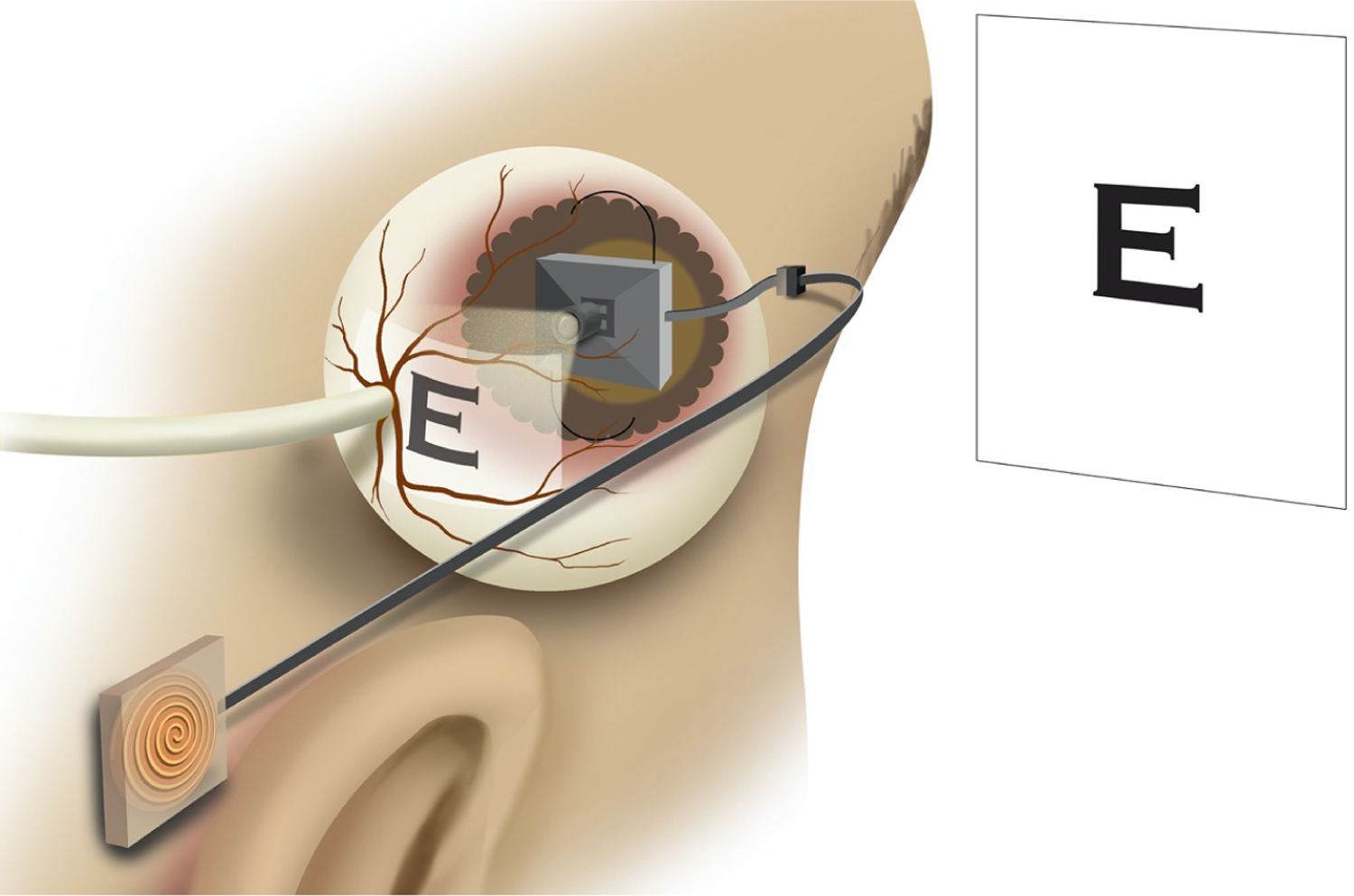
An intraocular projector device implanted in the eye. Receiver coil is implanted behind the ear which sends data and power to the projecting device, which projects image onto the retina.
Figure 2:
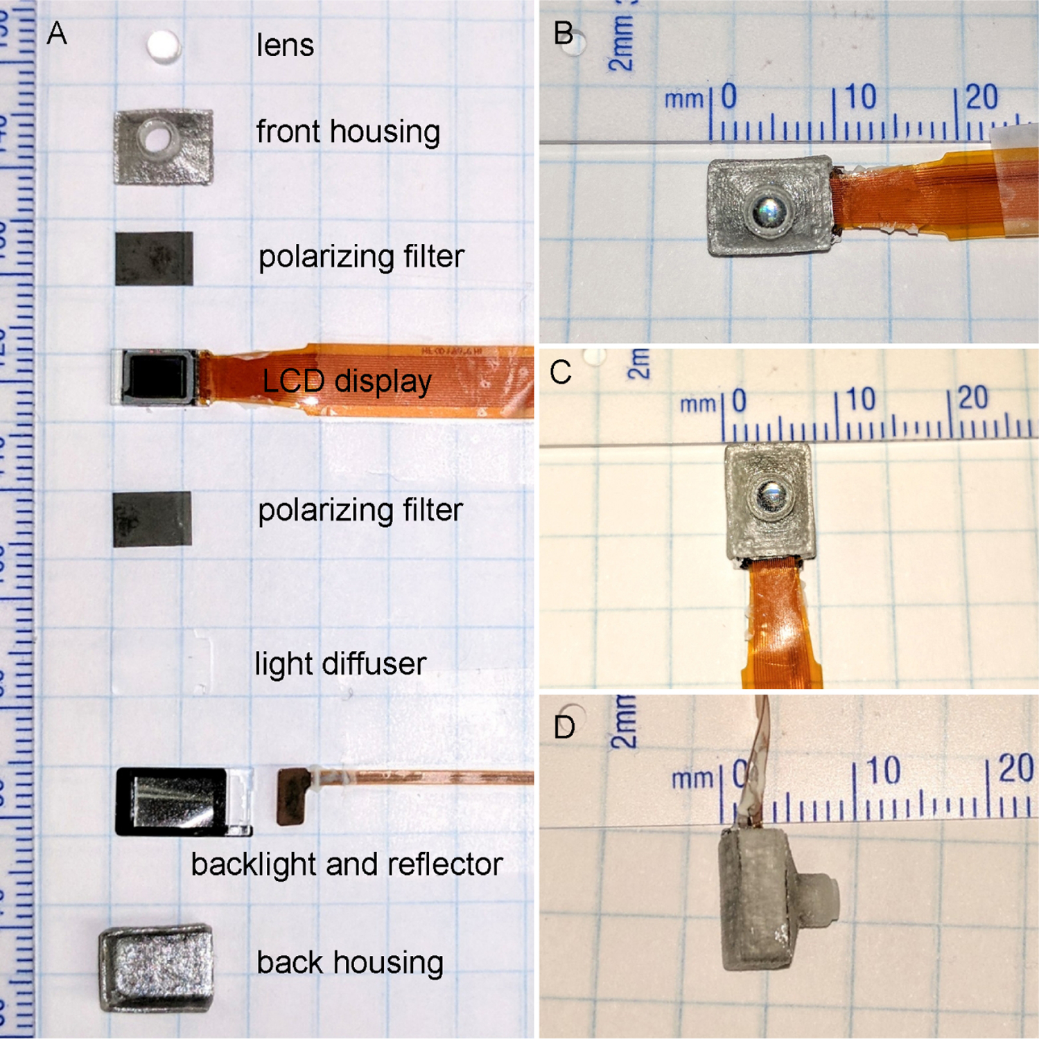
A) Components of intraocular projecting device. B–D) Measurements of the assembled projecting device that will replace the eye lens.
During the operation of the device, thermal energy is dissipated to the surrounding saline solution, resulting in an increase in the temperature of the eye tissue. The elevated temperature may result in permanent tissue damage depending upon the temperature it is exposed to and the duration of the exposure [11, 12]. The AIMD (Active Implantable Medical device, ISO 14708–1:2014) has provided a guideline to limit the temperature increase to 2°C above the body temperature [13]. We conducted a preliminary analysis of the intraocular device using an axisymmetric 2-dimensional model, which showed that the iris temperature increased by 2°C when operating at 100mW power. The elevated iris temperature decreased by 0.24°C when the air gap in the device was increased by 0.5 mm [14].
In this study, we present a 3-dimensional finite element simulation of the device to study the thermal elevation in the ocular tissues at operating power ranging from 25mw – 100mW and determine the threshold for power that the device can operate safely without compromising the medical device temperature limit.
Heat transfer in the eye is mainly through conduction, with convection, evaporation, and radiation also playing roles. There is a convection heat transfer from the anterior part of the eye exposed to the surrounding air and from the posterior sclera region to the body. Heat is lost from the corneal surface through radiation and evaporation of tear film. The flow of aqueous humor inside the eye also transfers heat between the anterior and posterior regions of the eye. However, the effect is negligible [15]. The blood flow in the choroidal region helps to thermoregulate the eye temperature. In this study, we have not taken into account the effect of blood perfusion.
Scott [16] and Rafiq et al. [17] developed a mathematical thermal model of the human eye to generate steady-state eye temperature distribution and showed that the thermal conductivity of lens, choroidal blood flow, basal temperature, and cornea convection affect the temperature distribution in the eye. Factors like evaporation and room temperature affect the temperature of the anterior region of the eye. Ng et al. [18] performed 2D finite element steady-state thermal analysis of the human eye and compared the results with experimental measurements, showing an error of only 0.33%.
The generation of reliable thermal eye models have been shown to accurately predict the thermal response due to implanted electronic devices. Several thermal studies have been carried out by developing thermal models of the eye for retinal implants for treating retinitis pigmentosa and age-related macular degeneration [12, 19–21]. These studies show that the temperature increase in the eye depends upon the total dissipated power, location of the implant, material, and size of the device.
Gosalia et al. [20] observed that the ciliary muscle temperature increased by 0.36°C and 0.19°C when 4 × 4 × 0.5 mm chip dissipating 12.4 mW power was placed in the anterior of the eye and center of the eye, respectively. The study also showed that a larger chip of size 6 × 6 × 1 mm produced 0.11°C less temperature change in the vitreous humor when dissipating the same amount of power. Lazzi et al. [12] demonstrated that when 4 × 4 × 0.5 mm chip placed at the center of the eye, the temperature at the device surface increased by approximately 2.1°C for an increase in power by 37.2 mW. Opie et al. [21] showed that 5 × 5 mm retinal implant in the suprachoroidal region can safely dissipate power up to 135 mW, but that an implant in the retina can dissipate power no more than 36.6 mW to meet the safety requirement.
Similar results were obtained by Piyathaisere et al. [11] for in vivo experiments carried out on dog eyes. A heater probe of size 1.4 × 1.4 × 1 mm in the vitreous cavity dissipating 500mW induced 5°C temperature change in the vitreous humor and 2°C in the retina. A histological study of the tissue showed no damage to the retina tissue. When the heater probe dissipating 50mW was brought in direct contact with the retina for less than 1 second, visible damage to the retina tissue was observed. However, permanent damage to the retina was detected only for power at 100mW.
2. Finite Element Model
Two different prosthesis-implanted finite element models were created to perform the thermal analysis study. The two models were based on two different sets of geometry data. The projector models were identical, and the material properties and the boundary conditions were also kept identical.
Model 1
An anatomically accurate three-dimensional model of the human eye was created following dimensions given in the Atlas of the Human Eye [22] supplemented by data provided by US Army Research Laboratory [23] where measurements were not available. The geometry was created on Creo Parametric for analysis. For simplicity in modeling and analysis, zonule fibers were modeled as one single lumped mass attached to the ciliary body and lens. Due to the lack of accurate iris dimensions in existing research, the design was approximated based on Li and Huang [24]. The aqueous and vitreous humors were designed by filling the void space left by the tissues. The Optic Nerve Head (ONH) was modeled as a cut at the posterior end at a 10° offset from the optical axis. The size of the eye was 24.79 mm along anterior-posterior direction and 24 mm in transverse and vertical directions.
Model 2
The eye model created by Pawar [25] was used as the second model for the analysis. The model was based on a three-dimensional model created by the US Army Research Laboratory [23]. The ONH was modeled with 10° offset from the optical axis towards the nasal side. The iris was also included in the model based on Caroline [26]. The eye measured 24.76 mm along anterior-posterior direction and 24 mm along transverse and vertical direction. The eye model was created in CATIA V5 software.
The projector to be placed inside the eye in place of the lens was 7.5mm in total height. The microdisplay (8 × 6 × 1 mm) made of glass was attached with a reflector (6.5 × 6 × 1 mm) and an LED (2 × 1.5 × 1 mm) both made of ABS plastic, this whole assembly was attached to the inside wall of the casing which was made of PMMA with 0.1mm thick adhesive. The lens was attached at the front of the projector, which was 0.5mm thick while the back of the projector was 9 × 7 mm (Figure 3).
Figure 3:
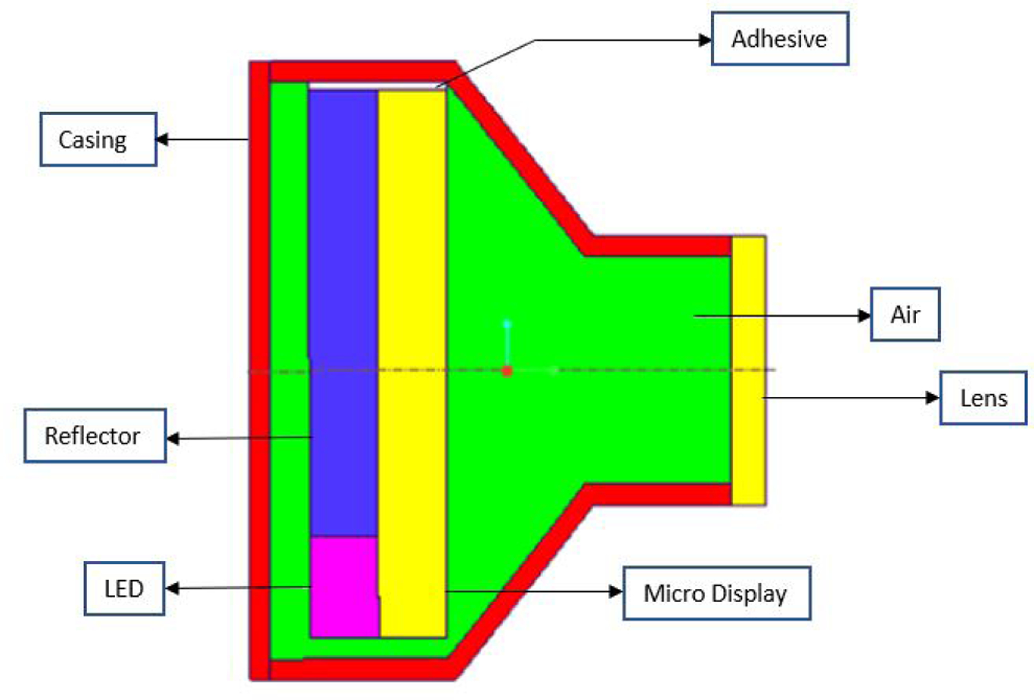
Cross section view of the Intraocular Projector. It consists of microdisplay, LED, and reflector attached by glue to the projector casing. The projector lens is installed at the front of the projector which focuses image to the retina.
To attach the projector in the eye, the lens was removed from the model and replaced with the projector. Using boolean operations, the original eye lens and zonule fibers were removed from the vitreous humor, and then the projector was “added” into it (Figure 4). Also, as in surgery, the fluidic vitreous humor was replaced by saline solution.
Figure 4:
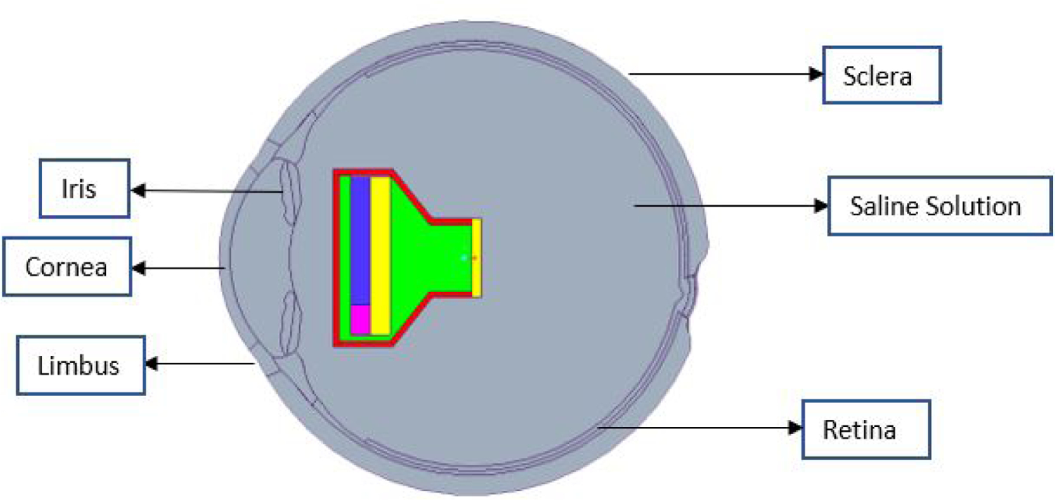
Sectional view of the eye model with projector implanted in the anterior region replacing Lens, and saline solution replacing vitreous humor.
The material properties of the eye components are taken from other thermal models in the literature [21,27–32], which have been validated by experimental data. The material properties of the eye tissues and the projector parts used in the analysis are given in Table 1.
Table 1:
Material properties of eye and projector components
A sensitivity analysis was carried out to compare the temperature values resulting from the different range of thermal conductivity values for the device. It was seen that the temperature values did not differ significantly, and so an average value was taken for the conductivities in the final simulations.
The entire projector assembly was at 9.98 mm from the retina of the eye to the lens of the projector along the optical axis. The Finite Element model of the entire assembly was made in ANSYS. The eye model was tested at extreme conditions of 40°C outside temperature, and body temperature was assumed to be 37°C [16]. The convection boundary conditions was applied on sclera with film coefficient of 65W/m2 °C at 37°C [21] and on cornea and limbus with film coefficient of 10W/m2 °C at 40°C [16]. A radiation boundary condition was applied on limbus and cornea with emissivity value of 0.975 at 40°C along with evaporation rate of 40W/m2 [16]. The internal heat generation on the microdisplay was kept constant at the magnitude of 25mW, but the heat generation on the LED was tested at different magnitudes to check the temperatures inside the eye and how they differed according to the power dissipated in the LED.
The models were meshed at fine setting with all established contact regions (Figure 5). The final mesh had a total number of 125,145 and 109,293 elements for Model 1 and Model 2, respectively. Mesh refinement was based on the convergence study carried out on the resulting maximum temperature on the iris.
Figure 5:
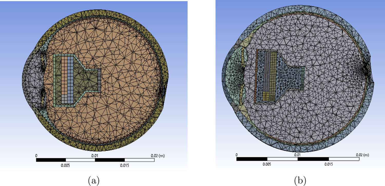
Meshed Models (a) Shows meshing for Model 1. Total number of elements = 125,145 and nodes = 240,084. (b) Shows meshing for Model 2. Total number of elements = 109,293 and nodes = 201,826.
Some changes to the model were made as the temperature in the iris, nearest live tissues of the eye, was more than the 2°C limit prescribed by the AIMD at higher power values. The projector was extended by 0.5mm towards the rear as more air would act as a good insulator of heat and still keeping the projector within the weight restrictions (Figure 6). An alternate design with high thermal conductivity material (thermal paste) was modeled and placed behind the LED between microdisplay and the casing to facilitate heat flow towards the back of the projector. The results from both the modifications satisfied the thermal increase limit. Another option explored was placing a conducting material in front of the microdisplay to lead heat out the front of the projector and away from the iris. Some improvement was noted, but the effect was small compared to other options. Hence, the conductor options were not further studied.
Figure 6:
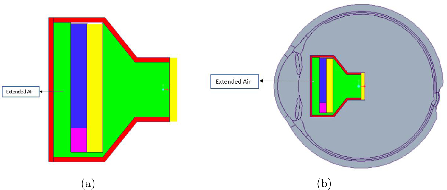
(a) Model of modified projector with extended air gap (0.5mm) between the casing and the LED (b) Model of the eye with modified projector implanted at ∼10mm distance from the retina to the lens of the projector.
3. Results and Analysis
The finite element models were simulated at different power inputs to the LED of 25mW, 50mW, 75mW, and 100 mW while all the other boundary conditions were constant for all the simulations. For the original model discussed above, the temperature inside the iris was 39.356°C for Model 1 and 39.183°C for Model 2 for 100mW power input, which exceeds the 39°C limit value. In the revised design, air acted as a good insulator as predicted, and the temperature inside the iris was down to 38.952°C for Model 1 and 38.752°C for Model 2 which is below the 39°C limit. The maximum temperature in the iris for the original model and final model are given in Table 2 and 3, respectively.
Table 2:
Maximum temperature in iris for the original projector design
| Power Input(mW) | Model 1 (°C) | Model 2 (°C) |
|---|---|---|
| 25 | 37.830 | 37.754 |
| 50 | 38.338 | 38.202 |
| 75 | 38.847 | 38.641 |
| 100 | 39.356 | 39.183 |
Table 3:
Maximum temperature in iris for the final projector design
| Power Input(mW) | Model 1 (°C) | Model 2 (°C) |
|---|---|---|
| 25 | 37.692 | 37.631 |
| 50 | 38.112 | 37.965 |
| 75 | 38.532 | 38.317 |
| 100 | 38.952 | 38.752 |
It was observed for the original model that the temperature rise in the iris was in the acceptable region until 75mW. Similarly, for the final model, the temperature rise was acceptable until 100mW. Figure 7 shows the temperature distribution for Model 1 and 2.
Figure 7:
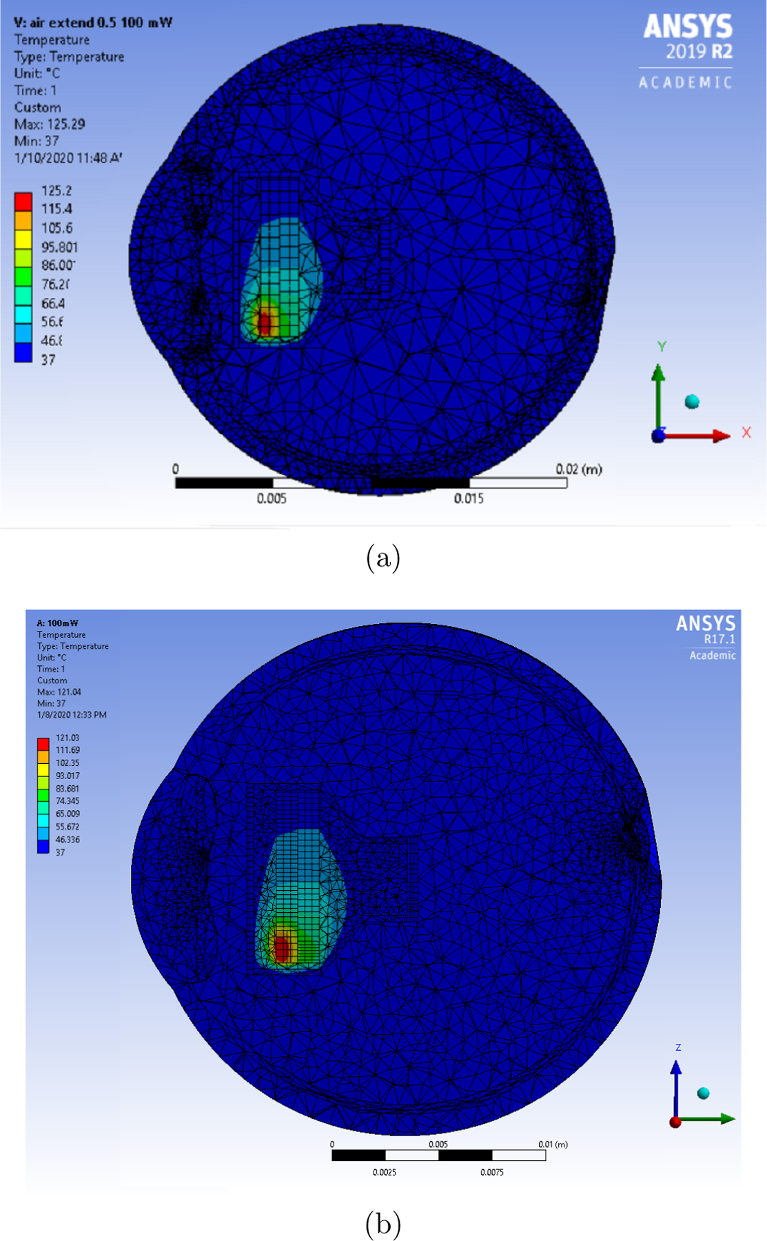
Temperature distribution for the final eye model (extended air) for LED operating at 100mW and microdisplay at 25mW. (a) Temperature distribution for Model 1 (b) Temperature distribution for Model 2.
Figure 8 shows that the temperature in the iris increases linearly as the power increased. For Model 1, the original model can safely operate at 82mW where the maximum temperature in the iris reaches 38.989°C. For Model 2, it can safely operate at 91mW where the maximum temperature in the iris reaches 38.987 °C.
Figure 8:
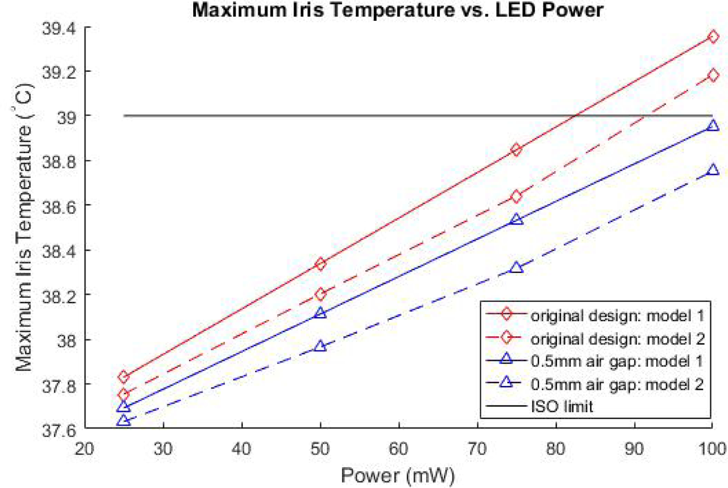
Linear relationship observed between Iris temperature and power.
4. Conclusion
In this study, we analyzed the temperature rise in an intraocular projector implanted eye models. Two models were used to evaluate the maximum power that the projector can operate without increasing the tissue temperature by more than 2°C. The two models were generated based on different sets of eye geometry data. The shape and size of the eye are unique for each patient. Moreover, the shape of the eye changes as the person ages. The study showed that the difference in eye geometry affects the temperature increase in the eye tissue. It was observed that the average difference between the maximum temperature of the iris was 0.15°C for the two models.
The projector, when placed ∼10 mm from the retina, can operate up to 82mW and 91mW for Model 1 and Model 2, respectively. The models were modified by increasing the gap between the LED and projector outer casing by 0.5 mm. The updated final model, with a large volume of air, can operate up to 100mW. This is the maximum power expected from the LED.
This study suggests 100 mW is the approximate power budget limit for this type of intraocular electronic device. We believe these results provide important new information on the power and heat budget available to electronic intraocular devices. While currently intraocular projectors and retina prosthesis are under testing for vision restoration in blind eyes, electronic intraocular implants could one day see more widespread adoption as vision augmentation devices.
The models did not account for fluid convection in the saline solution or choroidal blood perfusion. These processes would likely increase heat dissipation and decrease temperature, and are subjects of ongoing investigations.
5. Acknowledgements
The authors would like thank John Stark and Torna Patil for their help and feedback on the models. This research is partially funded by US Department of Defense grant VR180058 and US NIH National Eye Institute grant K08EY27469. This support is gratefully acknowledged.
References
- [1].Resnikoff S, Pascolini D, Kocur I Etya’ale D, Pararajasegaram R, Pokharel G, and Mariotti S. Global data on visual impairment in the year 2002. Bulletin of the World Health Organization, 82(11):844–851, December 2004. [PMC free article] [PubMed] [Google Scholar]
- [2].Flaxman SR, Bourne RRA, Resnikoff S, Ackland P, Braithwaite T, Cicinelli MV, Das A, Jonas JB, Keeffe J, Kempen JH, Leasher J, Limburg H, Naidoo K, Pesudovs K, Silvester A, Stevens GA, Tahhan N, Wong TY, Taylor HR, Bourne R, Ackland P, Arditi A, Barkana Y, Bozkurt B, Braithwaite T, Bron A, Budenz D, Cai F, Casson R, Chakravarthy U, Choi J, Cicinelli MV, Congdon N, Dana R, Dandona R, Dandona L, Das A, Dekaris I, Monte MD, Deva J, Dreer L, Ellwein L, Frazier M, Frick K, Friedman D, Furtado J, Gao H, Gazzard G, George R, Gichuhi S, Gonzalez V, Hammond B, Hartnett ME, He M, Hejtmancik J, Hirai F, Huang J, Ingram A, Javitt J, Jonas J, Joslin C, Keeffe J, Kempen J, Khairallah M, Khanna R, Kim J, Lambrou G, Lansingh VC, Lanzetta P, Leasher J, Lim J, LIMBURG H, Mansouri K, Mathew A, Morse A, Munoz B, Musch D, Naidoo K, Nangia V, Palaiou M, Parodi MB, Pena FY, Pesudovs K, Peto T, Quigley H, Raju M, Ramulu P, Rankin Z, Resnikoff S, Reza D, Robin A, Rossetti L, Saaddine J, Sandar M, Serle J, Shen T, Shetty R, Sieving P, Silva JC, Silvester A, Sitorus RS, Stambolian D, Stevens G, Taylor H, Tejedor J, Tielsch J, Tsilimbari M, Meurs J, Varma R, Virgili G, Wang YX, Wang N, West S, Wiedemann P, Wong T, Wormald R, and Zheng Y. Global causes of blindness and distance vision impairment 1990–2020: a systematic review and meta-analysis. The Lancet Global Health, 5(12):e1221–e1234, 2017. [DOI] [PubMed] [Google Scholar]
- [3].Pascolini D and Mariotti SP. Global estimates of visual impairment: 2010. British Journal of Ophthalmology, 96(5):614–618, 2012. [DOI] [PubMed] [Google Scholar]
- [4].Witcher JP, Srinivasan M, and Upadhyay MP. Corneal blindness: a global perspective. Bulletin of the World Health Organization, 79(3):214–21, 2003. July 7. [PMC free article] [PubMed] [Google Scholar]
- [5].Akpek EK, Alkharashi M, Hwang FS, Ng SM, and Lindsley K. Artificial corneas versus donor corneas for repeat corneal transplants. Cochrane Database of Systematic Reviews, (11), 2014. [DOI] [PMC free article] [PubMed] [Google Scholar]
- [6].Thompson RW, Price MO, Bowers PJ, and Price FW. Long-term graft survival after penetrating keratoplasty. Ophthalmology, 110(7):1396–1402, 2003. [DOI] [PubMed] [Google Scholar]
- [7].Bartels MC, Doxiadis II, Colen TP, and Beekhuis WH. Long-term outcome in high-risk corneal transplantation and the influence of hla-a and hla-b matching. Cornea, 22:552–556, August 2003. [DOI] [PubMed] [Google Scholar]
- [8].Gain P, Jullienne R, Zhiguo Z. He, Aldossary M, Acquart S, Cognasse F, and Thuret G. Global Survey of Corneal Transplantation and Eye Banking. JAMA Ophthalmology, 134(2):167–173, 02 2016. [DOI] [PubMed] [Google Scholar]
- [9].Shim SY, Gong S, Rosenblatt MI, Palanker D, Al-Qahtani A, Sun MG, Zhou Q, Kanu L, Chau F, and Yu CQ. Feasibility of intraocular projection for treatment of intractable corneal opacity. Cornea, 38(4):523–527, 4 2019. [DOI] [PMC free article] [PubMed] [Google Scholar]
- [10].Shim SY, Gong S, Fan VH, Rosenblatt MI, Al-Qahtani AF, Sun MG, Zhou Q, Kanu L, Vieira IV, and Yu CQ. Characterization of an electronic corneal prosthesis system. Current Eye Research, 0(0):1–7, 2020. [DOI] [PMC free article] [PubMed] [Google Scholar]
- [11].Piyathaisere DV, Margalit E, Chen SJ, Shyu JS, D’Anna SA, Weiland JD, Grebe RR, Grebe L, Fujii G, Kim SY, Greenberg RJ, De Juan E Jr., and Humayun MS. Heat effects on the retina. Ophthalmic Surg Lasers Imaging Retina., 34(2):114–120, Mar. Apr 2003. [PubMed] [Google Scholar]
- [12].Lazzi G. Thermal effects of bioimplants. IEEE Engineering in Medicine and Biology Magazine, 24(5):75–81, Sep. 2005. [DOI] [PubMed] [Google Scholar]
- [13].ISO 114708–1 Article 17.2, Implants for surgery Active implantable medical devices Part1: General requirements for safety, marking and for information to be provided by the manufacturer. Standard, International Organization for Standardization. [Google Scholar]
- [14].Stark JA, Foster CD, and Yu CQ. Axisymmetric thermal finite element analysis of effects of intraocular projector in the human eye. Under Review. [DOI] [PMC free article] [PubMed]
- [15].Emery AF, Kramar P, Guy AW, and Lin JC. Microwave Induced Temperature Rises in Rabbit Eyes in Cataract Research. Journal of Heat Transfer, 97(1):123–128, 02 1975. [Google Scholar]
- [16].Scott JA. A finite element model of heat transport in the human eye. Physics in Medicine and Biology, 33(2):227–242, February 1988. [DOI] [PubMed] [Google Scholar]
- [17].Rafiq A and Khanday MA. Thermal behavior of human eye in relation with change in blood perfusion, porosity, evaporation and ambient temperature. Journal of Thermal Biology, 62:138–142, 2016. [DOI] [PubMed] [Google Scholar]
- [18].Ng EYK and Ooi EH. FEM simulation of the eye structure with bioheat analysis. Computer Methods and Programs in Biomedicine, 82(3):268–276, 2006. [DOI] [PubMed] [Google Scholar]
- [19].Opie NL, Burkitt AN, Meffin H, and Grayden DB. Thermal heating of a retinal prosthesis: Thermal model and in-vitro study. 2010 Annual International Conference of the IEEE Engineering in Medicine and Biology, pages 1597–1600, Aug 2010. [DOI] [PubMed] [Google Scholar]
- [20].Gosalia K, Weiland J, Humayun M, and Lazzi G. Thermal elevation in the human eye and head due to the operation of a retinal prosthesis. IEEE Transactions on Biomedical Engineering, 51(8):1469–1477, August 2004. [DOI] [PubMed] [Google Scholar]
- [21].Opie NL, Burkitt AN, Meffin H, and Grayden DB. Heating of the eye by a retinal prosthesis: Modeling, cadaver and in vivo study. IEEE Transactions on Biomedical Engineering, 59(2):339–345, February 2012. [DOI] [PubMed] [Google Scholar]
- [22].Héctor Barajas M Atlas of the Human Eye: Anatomy & Biometrics. Palibrioy, 2015. [Google Scholar]
- [23].Thompson KA, Bhardwaj R, and Nguyen TD. Development of an anatomically accurate finite element human ocular globe model for blast-related fluid-structure interaction studies. US Army Research Laboratory report ARL-TR-7945, 2017.
- [24].Li Y and Huang D. Pupil size and iris thickness difference between asians and caucasians measured by optical coherence tomography. Investigative Ophthalmology & Visual Science, 50(3):1552–5783, 2009.19098318 [Google Scholar]
- [25].Pawar R. Design and finite element analysis of effects of therapeutic hypothermia in human eye. University of Illinois at Chicago, 2018. [Google Scholar]
- [26].Caroline P. The effect of corneal diameter on soft lens fitting. https://www.contamac-globalinsight.com/articles/the-effect-of-corneal-diameter-on-soft-lens-fitting/. Last accessed: 11/26/2019.
- [27].Wessapan T and Rattanadecho P. Heat transfer analysis of the human eye during exposure to sauna therapy. Numerical Heat Transfer, Part A: Applications, 68(5):566–582, 2015. [Google Scholar]
- [28].Nayar KG, Sharqawy MH, Banchik LD, and Lienhard V JH. Thermophysical properties of seawater: A review and new correlations that include pressure dependence. Desalination, 390:1–24, 2016. [Google Scholar]
- [29].Sharqawy MH, Lienhard V JH, and Zubair SM. Thermophysical properties of seawater: A review of existing correlations and data. Desalination and Water Treatment, 16:354–380, April 2010. [Google Scholar]
- [30].MIT.edu. 6.777j/2.751j Material properties database. http://www.mit.edu/~6.777/matprops/matprops.htm. Last accessed: 11/19/2019.
- [31].C-Therm Technologies. The thermal conductivity of unfilled plastics. https://ctherm.com/resources/blog/the_thermal_conductivity_of_unfilled_plastics/. Last accessed: 11/19/2019.
- [32].CHT. Thermally conductive silicone adhesive sealants. https://acc-silicones.com/products/adhesives/thermally-conductive-silicone-adhesives. Last accessed: 1/13/2020.


