Abstract
Stereotactic surgery is an essential tool in the modern neuroscience lab. However, being able to precisely and accurately target difficult to reach brain regions still represents a challenge, particularly when targeting brain structures along the midline. These challenges include avoiding the superior sagittal sinus and third ventricle and being able to consistently target selective, discrete brain nuclei. In addition, more advanced neuroscience techniques (e.g., optogenetics, fiber photometry, and 2-photon imaging) rely on targeted implantation of significant hardware to the brain and spatial limitations represent a common hindrance.
Here we present a modifiable protocol for stereotactic targeting of rodent brain structures using an angled coronal approach that may be adapted for 1) either mouse or rat; 2) various neuroscience techniques and 3) for multiple brain regions. As a representative example, we include calculation of stereotactic coordinates for targeting the mouse hypothalamic ventromedial nucleus (VMN) for an optogenetic inhibition experiment. This procedure begins with the bilateral microinjection of an adeno-associated virus (AAV) encoding a light-sensitive chloride channel (SwiChR++) to a cre-dependent mouse model, followed by the angled bilateral implantation of fiberoptic cannulae. Using this approach, our findings show that activation of a subset of VMN neurons is required for intact glucose counterregulatory responses to insulin-induced hypoglycemia.
Keywords: CNS, stereotactic surgery, microinjection, optogenetics, chemogenetics, fiber photometry
SUMMARY:
Here we describe an adaptable stereotactic procedure that can be utilized for targeting challenging and difficult to reach brain regions, due to spatial limitations, using an angled coronal approach. This protocol is adaptable to both mouse and rat and can be applied to diverse neuroscientific applications including implantation of cannulas and microinjections of viral constructs for fiber photometry and/or chemogenetic and optogenetic studies.
INTRODUCTION:
Neural control of behavior, feeding, and metabolism involves coordination of highly complex, integrative, and redundant neurocircuits, and a driving goal of the neuroscience field is to dissect the relationship between neurocircuit structure and function. Although classical neuroscience tools such as lesioning, local pharmacological injections, and electrical stimulation uncovered vital knowledge regarding the role of specific brain regions in control of behavior and metabolism, these tools were limited by their lack of specificity and reversibility1.
Recent advances in the neuroscience field have greatly improved our ability to interrogate and manipulate circuit function in a cell-type specific manner with high spatiotemporal resolution. Optogenetic2 and chemogenetic3 approaches, for instance, allow the rapid, reversible manipulation of activity in genetically defined cell types of freely moving animals. Optogenetics involves the use of light-sensitive ion channels, termed channelrhodopsins, to control neuronal activity. Key to this technique is gene delivery of the channelrhodopsin, and a source of light to activate the opsin. A common strategy for gene delivery is through a combination of 1) genetically-engineered mice expressing Cre-recombinase in discrete neurons, and 2) Cre-dependent viral vectors encoding channelrhodopsin. While optogenetics provides an elegant, highly precise means to control neuronal activity, the method is contingent upon successful stereotactic microinjection of the viral vector and fiberoptic placement into a defined brain region. Although stereotactic procedures are commonplace within the modern neuroscience lab, and there are several excellent protocols describing this procedure4–6, being able to consistently, reproducibly, and reliably target discrete brain regions along the midline, such as the mediobasal hypothalamus, a brain are critical in the regulation of homeostatic functions7, represents significant additional challenges. These challenges include avoiding the superior sagittal sinus, the third ventricle, and adjacent hypothalamic nuclei. In addition, there are significant spatial limitations for the bilateral implantation of hardware that is required for inhibition studies. With these challenges in mind, we herein present a modifiable procedure for targeting discrete brain regions via an angled stereotactic approach.
PROTOCOL:
All procedures should be approved in accordance with the National Institutes of Health Guide for the Care and Use of Animals and be approved by both the Institutional Animal Care and Use Committee and Environmental Health and Safety.
1. Calculate angled coordinates
-
1.1.
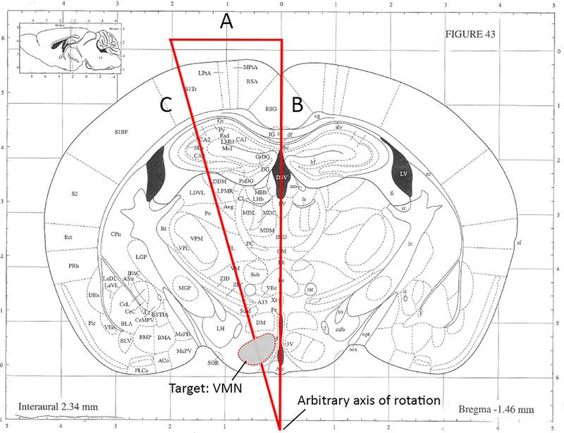
Using a coronal brain atlas, mark a right triangle so that the hypotenuse passes through the target region of interest. In the representative example (see Figure 1), the hypothalamic ventromedial nucleus (VMN) is targeted at a 15° angle from the coronal midline).
NOTE: The placement of the axis of rotation depicted in Figure 1 (and thus, the length of side C) is arbitrary and can be modified to target any brain region. Although this may seem counterintuitive, later steps in the protocol will adjust the position of the head in the Z axis such that this point aligns with the stereotactic center of rotation (see part 6). However, it is recommended not to exceed a coronal rotation angle of 15° due to physical constraints of the head holder apparatus.
-
1.2.
Establish the desired angle, a, and the estimated length of side B and use trigonometry to calculate the length of sides A and C. This step will be important for properly positioning the head during rotation.
-
1.2.1.In the example in Figure 1, atlas gridlines were used to approximate the length of side B, giving 7.576mm; this information was used to calculate the length of side A thus:
-
1.2.1.
-
NOTE: In this example, 2.03mm indicates the R/L distance from midline where the fiberoptic cannula will enter the brain when the head is rotated by 15°.
-
1.2.2.Optionally, calculate the length of side C in order to approximate the D/V coordinate:
-
1.2.2.
-
NOTE: The length of the hypotenuse, C, does not represent the depth of injection, but will be helpful in determining the D/V coordinate, which may need to be adjusted to accommodate for the increased length vs. side B for straight-in injections. It is therefore recommended to perform test injections to optimize the D/V coordinate.
In this example targeting the VMN, we therefore have two sets of coordinates, one for the microinjection that is non-angled (A/P: −1.4, R/L: 0.4 at 0°, D/V: −5.7) and one for the angled fiberoptic implantation (A/P: −1.4, R/L: 0.0 at 15°, D/V: −5.4).
Figure 1: Representative example for calculating angled coordinates targeting the hypothalamic ventromedial nucleus.
(angles and line segments not drawn to scale). A. This length should be calculated using basic trigonometry. Per this example, A = 2.03mm. B. Estimated length based upon assignment of arbitrary axis of rotation. Per this example, B = 7.576mm. C. Calculated hypotenuse. Note that the depth of fiberoptic/needle insertion used will depend upon desired proximity to target region and requires optimization. Modified from Kopf Carrier #96.
2. Prepare the stereotax for angled procedure
-
2.1.
Confirm that the stereotactic frame and micromanipulator have been calibrated (see Kopf Manual for full protocol).
-
2.2.
Place the Center Height Gauge into the socket of the head holder base plate.
-
2.3.
Secure the Centering Scope in the tool holder, then sight down the scope. Adjust the position of the micromanipulator until the crosshairs are aligned and focused on the gauge crosshairs.
NOTE: During this step, the scope is being positioned into the focal plane of the head holder’s center of rotation. Once established, the micromanipulator should not be moved during the remaining steps.
-
2.4.
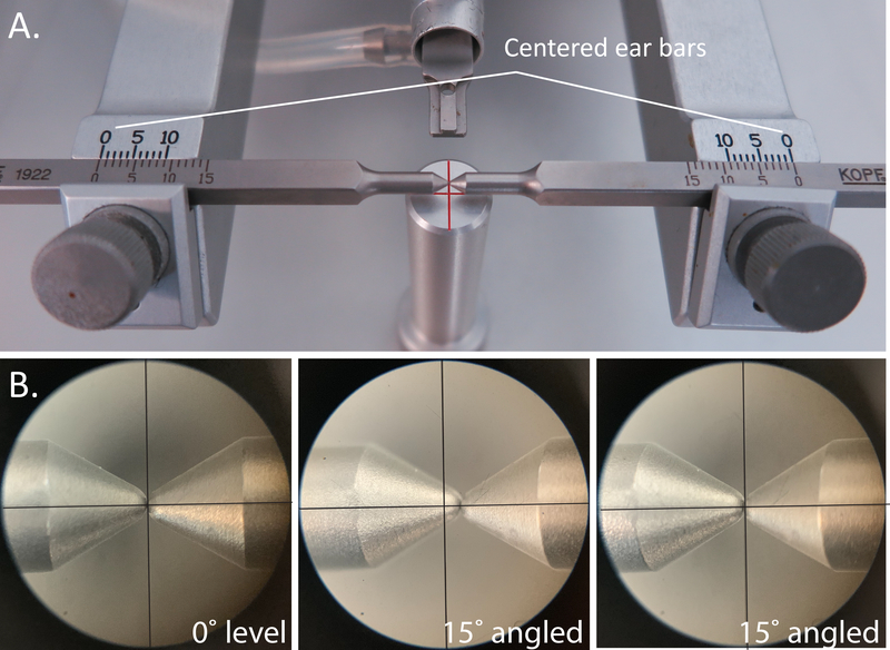
Place the ear bars into the holders and center them such that the indicator lines on both sides are at 0 (Figure 3A).
-
2.5.
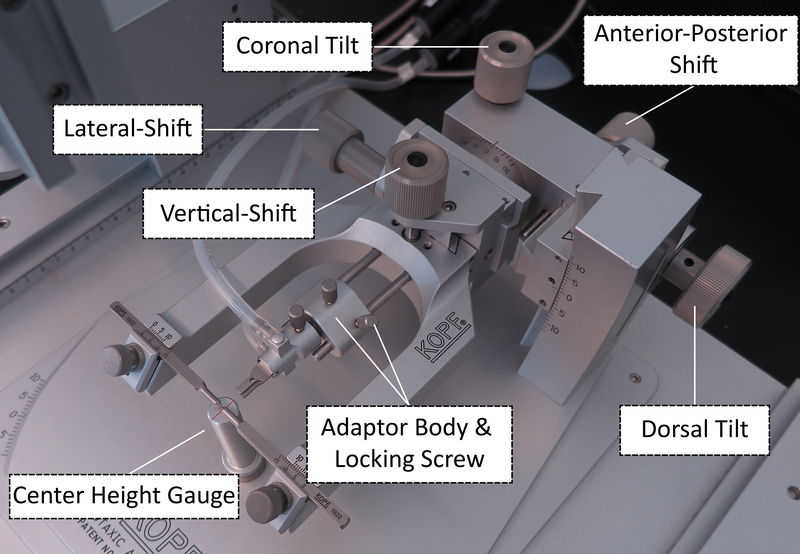
Use the Medial-Lateral and Anterior-Posterior knobs on the head holder (Figure 2) to center-align the ear bars in the X and Y planes above the crosshair of the Center Height Gauge (Figure 3A).
-
2.6.
To align the ear bar position in the Z axis, remove the ear bars from the holder and remove the Center Height Gauge. Replace the ear bars and again center them at 0.
-
2.7.
Sight down the scope. Use the Vertical Shift knob (Figure 3B) and Coronal Tilt knob, respectively to lower and rotate the ear bars until the scope crosshairs remain centered between the ear bars throughout coronal rotation.
-
2.8.
The stereotax is now calibrated and ready. Do not make any further adjustments to the position of the head holder.
Figure 3: Aligning the head holder center of rotation.
A. Positioning the ear bars. B. Sighting down the scope during 0° level coronal rotation (left), during 15° rotation before adjusting the Vertical Shift and the center of rotation is misaligned (middle), and during 15° rotation after adjusting the Vertical Shift, and the center of rotation is properly aligned (right). Modified from Kopf Carrier #96.
Figure 2: Adjustment knobs for the stereotactic head holder apparatus.
Modified from Kopf Carrier #96.
3. Prepare materials for injection/implantation.
-
3.1.
Ensure all instruments, surgical tools, and materials are sterilized and placed in a sterile surgical field next to the stereotax.
-
3.2.
Handle and store viral constructs according to their biosafety level and recommended guidelines.
-
3.3.
Draw up virus into the syringe, taking care to use proper handling practices and personal protective equipment.
4. Anesthesia.
-
4.1.
Record body weight prior to surgery.
-
4.2.
Deeply anesthetize mouse using isoflurane.
-
4.3.
Ensure animal is deeply anesthetized by performing toe pinch test until the flinching response is absent. If the animal continues to show strong reflexes, increase the concentration and/or duration of anesthesia.
-
4.4.
Shave the scalp from just behind the ears to just behind the eyes with a hair clipper.
-
4.5.
Apply eye ointment to each eye to keep them moist during surgery.
-
4.6.
Continuously monitor the animal throughout the surgical procedure and provide thermal support, if required.
5. Surgical Procedure.
-
5.1.
Place the head into the head holder by placing the upper incisors into the gap in the bite bar, making sure that the tongue is below the bite bar.
-
5.2.
Secure the head in the ear bars by gently inserting the ear bars into the external auditory meatus, taking care that the ear bars are symmetrically placed (typically between 3 and 4 for an adult mouse). This step is critical to ensure the head is stable and centered for rotation.
-
5.3.
Sterilize the shaved incision area with 3 alternating scrubs of betadine and alcohol swabs.
-
5.4.
Expose the skull by making an incision along the sagital midline of the scalp. Gently scrape the surface of the skull to remove any fascia and expose the sutures.
NOTE: If suture lines are difficult to visualize, hydrogen peroxide can be applied to the skull using a sterile cotton-tipped applicator to improve suture visualization.
-
5.5.
Place the Centering Scope into the holder and center the crosshairs on bregma (Figure 4, left panel). Zero the micromanipulator.
-
5.6.
Move the crosshairs caudally to lambda, noting the bregma-lambda (B-L) distance.
NOTE: If the suture lines do not follow a straight line along the midline, it is recommended that the midline should be established by the “line of best fit” through both bregma and lambda. However, if the above steps are followed, the initial placement of the scope reticle should be halfway between the ear bars and closely approximate the B-L midline suture.
-
5.7.
If B-L distance is significantly less or greater than 4.21mm, incrementally adjust the assigned bregma to obtain a B-L distance of 4.21 +/− 0.2 mm.
-
5.8.
Replace the centering scope with the Alignment Indicator. by Place the probes on lambda and bregma and adjust the Dorsal Tilt knob on the head holder to level in the sagital plane (nose-up or down); use the Centering Scope to reassign bregma.
-
5.9.
Use the Alignment Indicator to level in the coronal plane using the Coronal Tilt knob. Measure at multiple points throughout the rostral/caudal axis to account for surface deformations in the skull.
-
5.10.
Make sure to note the position on the dial of the coronal tilt knob – this is the 0° rotation position.
Figure 4: Assigning bregma and aligning the animal head with the central axes of rotation.
A. Representative image indicating typical bregma placement. B. Drawing a reference mark while head is level, before alignment. C. Properly aligned axis of rotation, after adjusting the Vertical Shift and readjusting bregma.
6. Aligning central axes of rotation for angled coordinate
-
6.1.Secure the Centering Scope in the tool holder and position the micromanipulator to the calculated coordinate from part 1. Note that the R/L coordinate for the angled implantation corresponds to the length of side A.
-
6.1.1.In the example in Figure 1, the angled coordinates for fiberoptic placement targeting the VMN are (A/P: −1.4, R/L: [2.03] at 0° coronal rotation, [0.00] at 15° coronal rotation, D/V: −5.4.
-
6.1.1.
-
6.2.
Sighting down the scope and mark this coordinate (R/L 2.03mm from the midline per the VMN example; Figure 4, middle panel); this mark represents where the cannula will enter the brain once the head has been rotated.
-
6.3.Reposition the micromanipulator over the midline (R/L: 0.00). Use the Coronal Tilt knob to rotate the head to the angle calculated in part 1.
-
6.3.1.If the scope crosshairs already line up with the mark, proceed to part 7.
-
6.3.2.If the scope crosshairs do not line up with the reference mark, adjust the head position in the Z axis using the Vertical-Shift knob (Figure 2) until the crosshairs line up as close as possible to the mark.
-
6.3.1.
-
6.4.
Rotate the head back to the 0° coronal position; if the Vertical Shift was adjusted in step 6.3, reassign bregma using the Centering Scope.
-
6.5.
Repeat steps 6.3 and 6.4 until the crosshairs consistently hit the reference mark when the head is rotated (Figure 4C).
-
6.6.
At this point, the arbitrary point of rotation established in part 1 should now be aligned with the stereotactic center of rotation.
7. Microinjection
-
7.1.Place the Stereotactic Drill in the holder and maneuver the micromanipulator to the first injection coordinate.
-
7.1.1.Per the example for targeting the VMN, drill at A/P: −1.4, R/L: 0.4 while head is level.
-
7.1.1.
-
7.2.
Lower the drill until the bit is just above the skull. Turn on the drill, and gently lower until the bit has just drilled through the skull (not the dura).
-
7.3.
Repeat for the contralateral injection site.
-
7.4.
Gently poke through the dura mater using the tip of a sterile 0.5mL insulin syringe that has been bent to 90°.
NOTE: If bleeding occurs, apply pressure with a sterile cotton-tipped applicator and clean with sterile water until the bleeding has stopped.
-
7.5.
When ready to inject, carefully place filled Hamilton syringe into stereotactic holder.
NOTE: The coordinates on the micromanipulator no longer apply after switching to a new tool. Use the center of the burr hole as the new target for injection.
-
7.6.
Carefully position the needle above the burr hole.
-
7.7.
Lower the needle until it just touches the dura within the center of the burr hole. CRITICAL STEP: Zero the micromanipulator only in the Z axis, such that the coordinates on the micromanipulator for the stereotactic centering scope and drill are maintained.
-
7.8.
Slowly lower the needle into the brain, watching closely to ensure the needle does not deflect on the edge of the burr hole. Continue to lower until 0.05mm ventral to the D/V injection coordinate and wait 1 minute; this extra step creates a small “pocket” to minimize viral backflow on needle removal.
-
7.9.
Slowly raise the needle to the D/V coordinate and start the injection.
NOTE: Flow rate and volume will vary depending on target region and experimental design. For optogenetic silencing of the VMN neurons, sufficient coverage was desired, and so 200nL virus was injected at a rate of 1nL/s.
-
7.10.
Following microinjection, wait 10 minutes at the injection site to minimize efflux of virus during withdrawal.
-
7.11.
Slowly withdraw the micropipette from the brain at an approximate rate of 1mm/minute.
-
7.12.
Once the needle is clear of the skull, eject a small volume of virus to ensure the needle has not clogged with blood or tissue. Use a sterile cotton-tipped applicator to remove the virus before continuing.
-
7.13.
Repeat steps 7.6 – 7.12 for the contralateral side.
-
7.14.
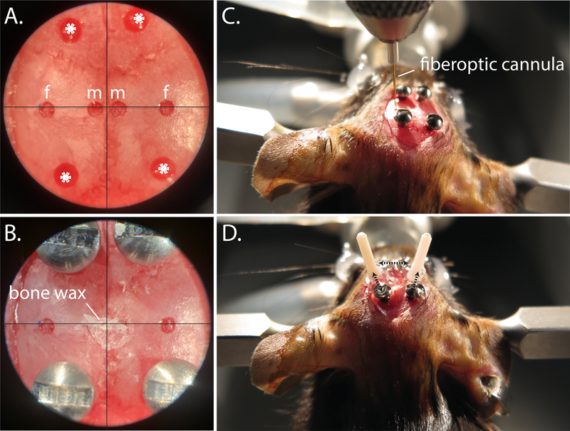
Seal the microinjection burr holes with bone wax to improve healing (Figure 5B).
Figure 5: Fiberoptic implantation procedure.
A. Centering scope view of pilot holes for microinjection (m), fiberoptic (f), and anchor screws (*). B. Centering scope view of implanted anchor screws, and bone wax covered microinjection drill holes. C. Positioning the fiberoptic into place during angled implantation. D. Representative bilateral angled fiberoptic placement; dotted black arrows indicate areas where super glue is used to anchor the fiberoptic to the anchor screws and to the ipsilateral fiberoptic.
8. Fiberoptic implantation
After viral injection, bilateral fiberoptic cannulas are implanted at the calculated angle per part 1. Note that these coordinates should already be marked on the skull from part 6.
-
8.1.
Follow steps 7.1 – 7.4 as described above for the angled coordinates.
-
8.2.
Return the head to the level 0° position.
-
8.3.
Next, use the hand drill to make 4 additional holes for the bone screws: 2 should be placed anteriorly, and 2 posteriorly (Figure 5A). These will serve as anchors to affix the fiberoptics to the skull (Figure 5D).
NOTE: Make sure to space these far enough away from the angled coordinate burr holes to accommodate the ferrule portion of the fiberoptic that sits above the skull.
-
8.4.
As gently as possible, use the small flathead screwdriver to set the bone screws such that they sit firmly in the skull but do not penetrate into the brain.
-
8.5.
Clamp a fiberoptic cannula into the cannula holder and place into the stereotactic holder.
-
8.6.
Rotate the head to the calculated angle, noting again that the coordinates on the micromanipulator do not apply to the new tool; use the center of the angled burr holes as the implantation target.
-
8.7.
Lower the fiberoptic until it just touches the dura within the center of the burr hole (Figure 5C). Zero the micromanipulator in the Z axis, then slowly slower the fiberoptic to the D/V angled coordinate (−5.4 per the VMN example).
-
8.8.
Use cyanoacrylate gel to connect the fiberoptic ferrule to the ipsilateral anchor screws, then apply an accelerant with a micropipette tip (Figure 5D).
-
8.9.
Once the cyanoacrylate gel has completely hardened, gently loosen the cannula holder and raise until clear of the fiberoptic ferrule.
-
8.10.
Repeat steps 8.5 – 8.9 for the contralateral angled coordinate, then level the head. For extra security, make an additional connection between the two angled fiberoptic cannulas with the cyanoacrylate gel and accelerant (Figure 5D).
-
8.11.
Prepare a small, relatively thin, amount of dental cement. Apply to the surface of the skull, making sure to thoroughly cover the anchor screws and the base of the fiberoptic cannulas but leaving enough of the ferrule clean for subsequent mating with the fiberoptic patch cables.
-
8.12.
Once the cement is completed dry, remove mouse from the stereotactic apparatus.
-
8.13.
Inject mouse subcutaneously with analgesic (buprenorphine; 0.5mg/kg)
-
8.14.
Place mouse in recovery cage with thermal support. Allow animal to recover and transfer them to their home cage once they appear alert, mobile and are grooming.
9. Post-surgical Care
-
9.1.
Monitor animals daily for three days post-operatively for both behavior, posture, activity and grooming and keep records of food intake and body weight.
-
9.2.
If animals exhibit any general indicators of pain or poor health, consult with Veterinarian Services.
-
9.3.
Allow mice at least 2 weeks for recovery and for viral expression before starting behavioral studies.
10. Optogenetics studies
-
10.1.
For the performance of optogenetics studies, please refer to Sidor et al., 20158.
-
10.2.
Validate viral expression and fiber placement at completion of studies.
REPRESENTATIVE RESULTS:
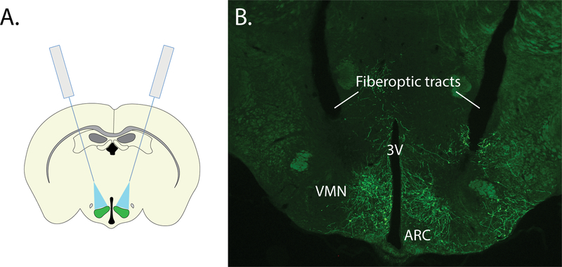
In this example, we describe the surgical procedure for performing optogenetics studies to interrogate the role of hypothalamic VMN neurons in glycemic control 9. In this study, we first utilized a standard (non-angled), stereotactic approach for the bilateral microinjection of an inhibitory channelrhodopsin virus to the VMN. While an angled approach would also be suitable, the standard (non-angled) approach was selected given that it was sufficient to target the brain region of interest and is an easy, reliable and consistent approach. However, given the VMN’s proximity to the midline, space constraints did not permit the non-angled implantation of bilateral fiberoptics, necessitating the development of a surgical strategy for precisely implanting fiberoptics at an angle (see Figure 6). Using this surgical strategy, we microinjected a cre-dependent AAV expressing a modified channelrhodopsin anion-conducting channel fused with the fluorescent reporter, referred to as a ”SwiChR++” virus10 bilaterally to the VMN of Nos1-cre mice, followed by implantation of an optic fiber dorsolateral to each injection site at a 15° angle from the midline. As expected, viral expression was restricted to the VMN and not detected in other brain areas.
Figure 6: Representative results for bilateral targeting of the ventromedial hypothalamus.
A. Schematic representing bilateral microinjection and angled fiberoptic strategy for targeting the VMN. B. Representative image showing bilateral expression of SwiChR-GFP and tissue damage from angled fiberoptic tracts. 3V: third ventricle, ARC: arcuate nucleus, VMN: ventromedial nucleus.
DISCUSSION:
Recent advances in neuroscience have supported advanced insight and understanding into the activity and function of brain neurocircuits. This includes the application of optogenetic and chemogenetic technologies to activate or silence discrete neuronal populations and/or their projection sites in vivo and more recently, the development of genetically-encoded calcium indicators (e.g. GCaMP, RCaMP) and other fluorometric biosensors (e.g. dopamine, norepinephrine) for in vivo recording of neuronal activity in a defined cell type in freely moving animals. Effective employment of these technologies, however, relies upon successful stereotactic surgery to target the region of interest. While there are several established protocols describing these procedures and are suitable for targeting many different brain regions, targeting deep brain regions along the midline represents significant additional challenges. Here we demonstrate a detailed surgical technique for targeting discrete brain regions via an angled stereotactic approach. Importantly, this technique can be adapted and applied to a diverse range of neuroscience techniques, including optogenetics, chemogenetics, and fiber photometry approaches.
Using this approach, we showed that acute optogenetic silencing of VMN neurons expressing neuronal nitric oxide synthase (VMNNOS1 neurons) blunts glucagon responses to insulin-induced hypoglycemia in mice9. Using a slightly modified approach, we further demonstrated that unilateral activation of VMNNOS1 neurons is 1) elicits robust hyperglycemia that is driven by counterregulatory responses that are normally reserved for the response to hypoglycemia and 2) defensive immobility behavior. Furthermore, these behavioral and metabolic responses involve neuronal projections to distinct brain areas such that activation of VMNNOS1 neurons that project to the anterior bed nucleus of the stria terminalis are involved in glycemic responses whereas VMNNOS1 neurons that project to the periaqueductal gray are linked to fear-induced behavior responses9.
We note that the protocol described is highly specific to the Kopf Model 1900 stereotax and its accompanying accessories. While this system enables precise, reproducible implantation and/or microinjection to discrete brain regions, with common centerline position across multiple tools, the strategy and approach can be adapted to suit other stereotaxic frames. Specifically, instead of rotating the head to perform angled microinjections and implantations, an alternative approach is to utilize the same principles and rotate the dorsal-ventral manipulator instead (see Correia et al.11).
As with any new method, it is critical for each individual to optimize his/her technique to improve their reliability, consistency, and accuracy. In addition, it is important to include the necessary appropriate controls for proper analysis and interpretation of data. These include the use of Cre-negative littermate controls, viral reporter controls (i.e. AAV-GFP), verification of light-dependent neuronal firing modulation using electrophysiology and, upon study completion validation of viral targeting and fiberoptic placement in the region of interest. Please refer to Cardozo & Lammel12 for a detailed review of technical considerations and suggested controls
In summary, the advent of more advanced and precise neuroscience techniques have supported a significant advancement and understanding of the role of the brain in behavior, cognition and physiology, and these advancements may one-day lead to potential therapies for CNS-related disorders.
ACKNOWLEDGMENTS:
This work was supported by the National Institute of Diabetes and Digestive and Kidney Diseases (NIDDK) grants F31-DK-113673 (C.L.F.), T32-GM-095421 (C.L.F.), DK-089056 (G.J.M.), an American Diabetes Association Innovative Basic Science Award (#1-19-IBS-192 to G.J.M.) and the NIDDK-funded Nutrition Obesity Research Center (DK-035816), Diabetes Research Center (DK-017047) and Diabetes, Obesity and Metabolism Training Grant T32 DK0007247 (T.H.M) at the University of Washington.
Footnotes
DISCLOSURES:
The authors have nothing to disclose.
REFERENCES:
- 1.King BM The rise, fall, and resurrection of the ventromedial hypothalamus in the regulation of feeding behavior and body weight. Physiol. Behav 87, 221–244 (2006). [DOI] [PubMed] [Google Scholar]
- 2.Boyden ES, Zhang F, Bamberg E, Nagel G, & Deisseroth K Millisecond-timescale, genetically targeted optical control of neural activity. Nat. Neurosci 8, 1263–1268 (2005). [DOI] [PubMed] [Google Scholar]
- 3.Roth BL DREADDs for Neuroscientists. Neuron 89, 683–694 (2016). [DOI] [PMC free article] [PubMed] [Google Scholar]
- 4.Richevaux L, Schenberg L, Beraneck M, & Fricker D In Vivo Intracerebral Stereotaxic Injections for Optogenetic Stimulation of Long-Range Inputs in Mouse Brain Slices. J. Vis. Exp e59534 (2019). doi: 10.3791/59534 [DOI] [PubMed] [Google Scholar]
- 5.Fricano-Kugler CJ, Williams MR, Luikart B, Salinaro JR, & Li M Designing, packaging, and delivery of high titer crispr retro and lentiviruses via stereotaxic injection. J. Vis. Exp e53783 (2016). doi: 10.3791/53783 [DOI] [PMC free article] [PubMed] [Google Scholar]
- 6.McSweeney C & Mao Y Applying Stereotactic Injection Technique to Study Genetic Effects on Animal Behaviors. J. Vis. Exp 99, e52653 (2015). [DOI] [PMC free article] [PubMed] [Google Scholar]
- 7.Lowell BB New Neuroscience of Homeostasis and Drives for Food, Water, and Salt. N. Engl. J. Med 380, 459–471 (2019). [DOI] [PubMed] [Google Scholar]
- 8.Sidor MM et al. In vivo optogenetic stimulation of the rodent central nervous system. J. Vis. Exp e51483 (2015). doi: 10.3791/51483 [DOI] [PMC free article] [PubMed] [Google Scholar]
- 9.Faber CL et al. Distinct Neuronal Projections from the Hypothalamic Ventromedial Nucleus Mediate Glycemic and Behavioral Effects. Diabetes 67, 2518–2529 (2018). [DOI] [PMC free article] [PubMed] [Google Scholar]
- 10.Berndt A et al. Structural foundations of optogenetics: Determinants of channelrhodopsin ion selectivity. Proc. Natl. Acad. Sci 113, 822–829 (2016). [DOI] [PMC free article] [PubMed] [Google Scholar]
- 11.Correia P, Matias S, & Mainen Z Stereotaxic Adeno-associated Virus Injection and Cannula Implantation in the Dorsal Raphe Nucleus of Mice. Bio-Protocol 7, (2017). [DOI] [PMC free article] [PubMed] [Google Scholar]
- 12.Cardozo Pinto DF & Lammel S Hot topic in optogenetics: new implications of in vivo tissue heating. Nat. Neurosci 22, 1039–1041 (2019). [DOI] [PMC free article] [PubMed] [Google Scholar]


