Abstract
The paper demonstrates an effective technique to significantly enhance the bandwidth and radiation gain of an otherwise narrowband composite right/left-handed transmission-line (CRLH-TL) antenna using a non-Foster impedance matching circuit (NF-IMC) without affecting the antenna’s stability. This is achieved by using the negative reactance of the NF-IMC to counteract the input capacitance of the antenna. Series capacitance of the CRLH-TL unit-cell is created by etching a dielectric spiral slot inside a rectangular microstrip patch that is grounded through a spiraled microstrip inductance. The overall size of the antenna, including the NF-IMC at its lowest operating frequency is 0.335λ0 × 0.137λ0 × 0.003λ0, where λ0 is the free-space wavelength at 1.4 GHz. The performance of the antenna was verified through actual measurements. The stable bandwidth of the antenna for |S11|≤ − 18 dB is greater than 1 GHz (1.4–2.45 GHz), which is significantly wider than the CRLH-TL antenna without the proposed impedance matching circuit. In addition, with the proposed technique the measured radiation gain and efficiency of the antenna are increased on average by 3.2 dBi and 31.5% over the operating frequency band.
Subject terms: Engineering, Electrical and electronic engineering
Introduction
Highly reliable and portable ultra-high frequency (UHF) wireless communication systems mainly employ monopole or dipole antennas. As the physical size of the antenna is proportional its operating wavelength, UHF-band antennas can have a length between 0.1 to 1 m. Various types of small UHF-band antennas have been previously proposed; however, they cannot be adapted for conformal installations and/or their bandwidth is limited1–3. Another method to reduce the antenna size is using metamaterials (MTMs) or left-handed (LH) (, ) materials4–6. In practice, when creating a MTM the parasitic elements associated with transmission-lines (TLs), i.e. right-handed (RH) (, ), combine with the LH characteristics to create a MTM structure commonly referred to as composite right/left-handed transmission-line (CRLH-TL)7. Antennas based on CRLH-TLs can be designed to operate in different modes, such as the zeroth-order resonance (ZOR) mode, + 1, and − 1 modes8,9. The zeroth-order resonance frequency makes CRLH-TLs independent of its physical dimensions. This property is taken advantage of here to miniaturize the antenna. As CRLH-TL can be easily realized using standard printed circuit board (PCB) technologies they have been used in the design of multiband antennas10, frequency reconfigurable antennas11 and pattern reconfigurable antennas8. However, the inherent narrow bandwidth of CRLH-TLs limits the range of applications of this type of antenna.
To overcome the bandwidth limitation of CRLH-TL antenna, it is necessary to introduce an active device that presents a negative reactance that counteracts the positive reactance of the antenna. This is achieved here with the use of a non-Foster impedance matching circuit. The challenging aspect of NF-IMC design is a stability-performance tradeoff, where instability leads to oscillation or latching. Optimal performance is achieved at the stability threshold, leaving little margin for error due to imperfect modeling, fabrication tolerances, and environmental changes. Numerous designs of the non-Foster circuit have been previously reported to realize wideband matching of electrically small antennas12–15. The improvement in the matching performance reported using NF-IMC is mainly in terms of reflection-coefficient, which does not completely characterize the antenna’s operational band.
In this paper we demonstrate that by combining the proposed non-Foster impedance matching circuit (NF-IMC) with a narrowband CRLH-TL microstrip antenna it is possible to significantly enhance the antenna’s bandwidth and radiation gain performance without compromising its stability. This is due to the negative reactance created by the NF-IMC that is used to cancel the antenna’s high and positive reactance over its operating frequency range. The proposed antenna described here is implemented with six unit-cells of CRLH-TL, where the equivalent circuit of each unit-cell consists of series left-handed capacitance and shunt spiral left-handed inductance. The size of the proposed antenna is 56 20 0.8 mm3 or 0.261 0.093 0.003 , where is at the minimum operation frequency of the antenna which is 1.4 GHz. The size of the non-Foster circuit is 0.074 0.044 (16 9.5 mm2). The proposed antenna has a measured bandwidth of > 1 GHz across 1.4–2.45 GHz for |S11|≤ − 18 dB, which is significantly wider than the CRLH-TL antenna without the non-Foster circuitry. With NF-IMC the measured antenna's radiation gain is shown to improve over its operating frequency range on average by approximately 3 dB.
Design of non-foster impedance matching circuit
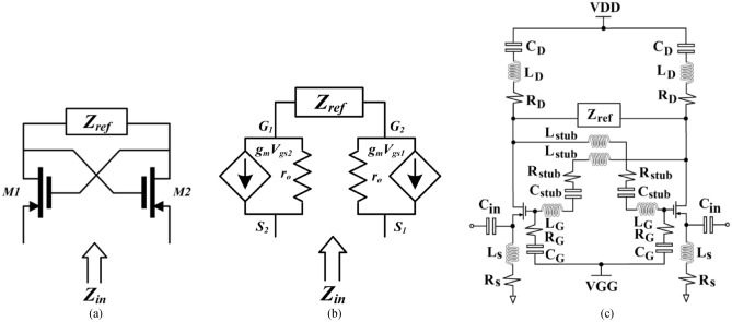
Impedance matching circuits (IMCs) using conventional passive elements such as a LC-circuit are applicable only for narrowband devices. To circumvent this issue the negative impedance property of NF-IMC is exploited here to reverse the reactance slope of conventional LC-circuits, as illustrated in Fig. 1, to thereby accomplish impedance matching over a wider band. The design of the NF-IMC is based on the generic principle described in16 involving the use of cross-coupled transistors, as shown in Fig. 2a. This circuit is utilized here to convert the load impedance (Zref) seen by the two transistors to its negative equivalent. Positive feedback loop is created by cross coupling the gate and drain of the two transistors, which is typically used to design an oscillator circuit. Therefore, avoiding oscillations and ensuring stability are critical in the design of the NF-IMC. In the cross-coupled transistor arrangement the phase of the current at the input and output are identical, but there is a phase difference between the input and output voltages of 180°. From the small-signal model of the simplified NF-IMC topology in Fig. 2b, it can be shown that
| 1 |
where and are the transistor’s output resistance and transconductance, respectively. Assuming and is large compared to , (1) can be approximated as The actual NF-IMC used in Fig. 2c was obtained through optimization using ADS from Keysight Technologies to provide impedance matching from 1.4 to 2.45 GHz. The optimized parameters of the NF-IMC are given in Table 1. Avago ATF-53189 transistor with an operating frequency of 50–6500 MHz was used here. The bias voltage VDD is 2 V.
Figure 1.
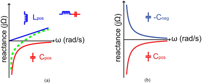
Matching with (a) Foster impedance, and (b) non-Foster impedance.
Figure 2.
Non-Foster impedance matching circuit (NF-IMC) obtained through optimization using ADS version 2019 from Keysight Technologies. (a) Basic topology, (b) equivalent small-signal model, and (c) equivalent circuit of the optimized NF-IMC design used here.
Table 1.
Parameters of the non-Foster impedance matching circuit (NF-IMC).
| Parameter | Value |
|---|---|
| 13 pF | |
| 125 pF | |
| 150 nH | |
| 700 Ω | |
| 8.5 pF | |
| 50 Ω | |
| 12 nH | |
| 50 pF | |
| 150 nH | |
| 700 Ω | |
| 125 pF | |
| 150 nH | |
| 700 Ω |
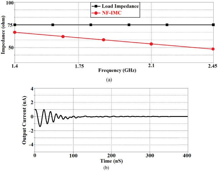
Active feedback is necessary in NF-IMC to realize the desired negative impedance. However, NF-IMCs can generate positive feedback when connected to the antenna system which can adversely affect its stability. As NF-IMC’s delicate stability is vulnerable to environmental changes, a small perturbation in antenna’s impedance could increase the positive feedback and make the NF-IMCs deviate from the stable condition into a large signal oscillator. It was therefore important to establish the stability of the NF-IMC. Stability over a wide band was achieved by cross coupling the transistors with series LC circuit. The stability was confirmed by checking impedance of the NF-IMC and the time domain transient response, as shown in Fig. 3. The stability was maintained by making the impedance of the non-Foster matching circuit smaller than the impedance of the antenna, which is confirmed in Fig. 3a over 1.4–2.45 GHz. Figure 3b shows the time domain transient response of the NF-IMC is stable after 0.2 microseconds of switching ‘on’ the NF-IMC.
Figure 3.
(a) Impedance of the proposed non-Foster matching circuit and load impedance (Zref), and (b) time domain transient response of the NF-IMC.
Design of proposed CRLH-TL antenna
The equivalent circuit of a typical CRLH-TL unit-cell is constituted from a left-handed (LH) and right-handed (RH) circuitry7, where the LH circuit is composed of the series capacitors () and the shunt inductors (). In practice, the unavoidable parasitic reactance elements are introduced in transmission-line structure, in particular series RH inductances () and the parasitic shunt RH capacitances () which compromise the existence of the purely LH circuit. The zeroth-order resonant frequency of the CRLH-TL is affected by these parasitic effects. Below the zeroth-order resonant frequency, CRLH-TL structure exhibits LH characteristics, and above zeroth-order resonant frequency, CRLH-TL exhibits RH characteristics. At the zeroth-order frequency, the resonant frequency is independent of the physical size. This property is exploited here to miniaturize the antenna. The zeroth-order resonant frequency is controlled by the series and shunt resonant frequencies defined by
| 2 |
| 3 |
The propagation constant (β) for a CRLH unit-cell is given by
| 4 |
where
| 5 |
Figure 4 shows the dispersion diagram of a typical CRLH-TL unit-cell when ωse and ωsh are unequal. At these resonant frequencies (ωse and ωsh) where β = 0, an infinite wavelength can be supported. According to the transmission-line theory CRLH-TL resonates at a frequency given by 7
| 6 |
where, l, n and N are the physical length of the resonator, mode number, and number of unit cells, respectively. When n is zero, the wavelength, λg = 2π/|βn|, becomes infinite and the resonant frequency of the zeroth-order mode becomes independent of the size of the resonator.
Figure 4.
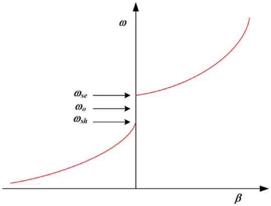
Dispersion curve of CRLH-TL unit-cell.
The antenna was designed by determining the reactance values in Eqs. (2) & (3) such that each of the two zeroth-order resonant frequencies define the boundary of the frequency range of interest. This was done by using the optimization tool in ADS by Keysight Technologies. The CRLH-TL unit-cell parameters were then converted to their physical implementation on microstrip technology, where is implemented by etching a spiral slot on a rectangular patch, and the is realized using a high impedance spiraled microstrip-line that is grounded with a metalized via-hole. The inductor was spiraled purely to minimize the spaced used. As mentioned earlier the parasitic RH elements ( & ) are unavoidable components in the transmission-line structure due to existence of the voltage gradient between the patch and ground plane, and the currents flowing on the surfaces, respectively13. As these parameters effect the overall frequency range of the antenna it was therefore necessary to optimize the structural parameters of the antenna unit-cell using ADS to realize the desired performance. The physical layout of the proposed antenna, which consists of a cascade of six unit-cells, and its equivalent circuit are shown in Fig. 5. The dispersion diagram of the CRLH-TL unit-cell depicted in Fig. 6 shows the LH and RH regions are 1.14 GHz < fLH < 1.41 GHz and 2.45 GHz < fRH < 3.6 GHz, respectively. It also shows the propagation constant of the CRLH-TL unit-cell is near zero in the frequency range of interest between 1.4 and 2.46 GHz. The simulation analysis in Fig. 7 reveals show the input impedance of the antenna is affected by the number of unit-cells. The antenna was implement using six unit-cells so that its impedance was compatible with the 50Ω NF-IMC board.
Figure 5.
The proposed CRLH-TL antenna, (a) layout, realized in CST Microwave Studio version 2019, and (b) equivalent circuit, obtained through optimization using ADS version 2019.
Figure 6.
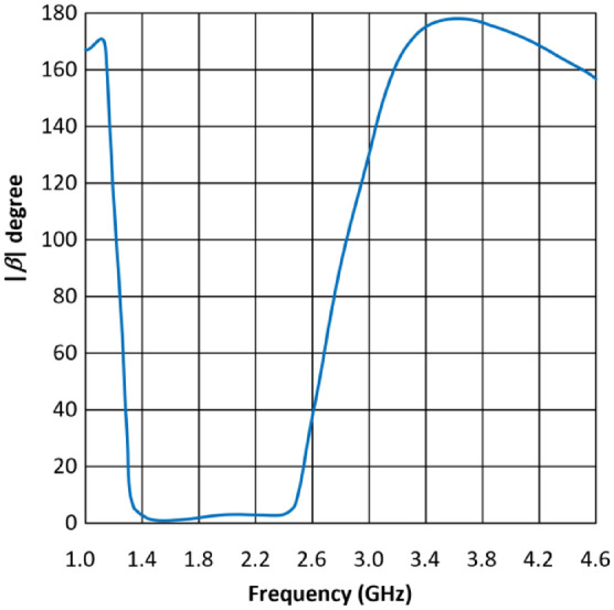
Dispersion diagram of the proposed CRLH-TL unit-cell.
Figure 7.
Input impedance of the CRLH-TL antenna as a function of number of unit-cells.
The proposed CRLH-TL antenna was constructed on the FR-4 lossy substrate with =4.4, thickness h = 0.8 mm, and tan =0.025. The equivalent circuit parameters of the CRLH-TL unit-cell were extracted using the pseudo-inverse method17 from the measured S-parameters. This involved converting the S-parameters to ABCD-parameters and the corresponding impedance and admittance from which the values of the lumped elements were obtained. The averaged values of the unit-cell parameters over the frequency of interest (1.4–2.45 GHz) are: , , , and . The structural parameters of the optimized antenna are given in Table 2, where is the free-space wavelength at 1.4 GHz.
Table 2.
Structural Parameters of the CRLH-TL Antenna.
| Number of spiral slot turns | 3 |
|---|---|
| Width of spiral slots | 0.75 mm |
| Gap between spiral slots | 0.75 mm |
| Gap between the unit-cells | 2.25 mm |
| Number of inductive spiral turns | 3 |
| Width of inductive spiral | 0.75 mm |
| Gap between the inductive spirals | 0.75 mm |
| Radius of the via-hole | 0.4 mm |
| Number of unit-cells | 6 |
| Unit-cell dimensions | 7 × 16 × 0.8 mm3 (0.032 0.074 0.003 |
| Antenna dimensions | 56 × 20 × 0.8 mm3 (0.261 0.093 0.003 |
| Ground-plane dimensions | 56 × 20 × 0.035 mm3 |
| Dimensions of feedline | 13 × 2.3 mm2 |
| Dimensions of NF-IMC board | 16 × 9.5 mm2 |
The input capacitance of the antenna is approximated by . The antenna’s input capacitance as a function of frequency is shown in Fig. 8. The input capacitance of the antenna was counteracted with the negative reactance generated by the NF-IMC and thereby overcome the inherent narrowband characteristic of the antenna.
Figure 8.
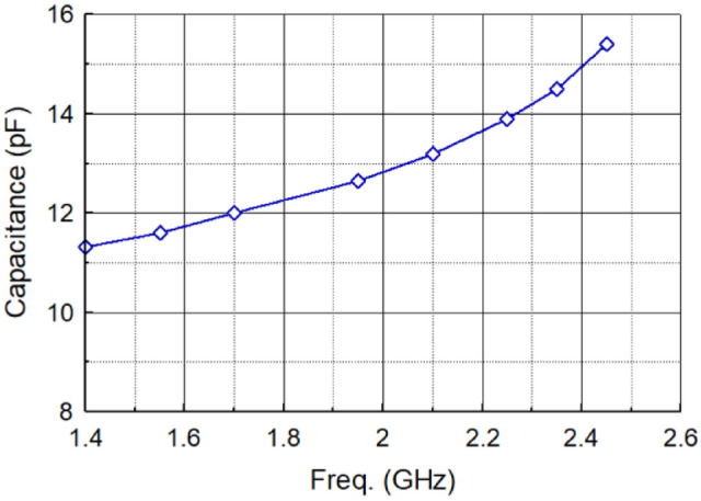
Input capacitance of the antenna as a function of frequency.
Fabricated prototype and measurements
The fabricated prototype of the proposed antenna based on CRLH-TL is combined with the NF-IMC as shown in Fig. 9. An SMA male to SMA male coupler is used to connect the antenna to NF-IMC board. With the antenna connected to the NF-IMC board the measured reflection-coefficient is better than − 18 dB across 1.4–2.45 GHz, which corresponds to a fractional bandwidth of 54.54%. Simulated and measured reflection-coefficient responses of the proposed antenna before and after applying NF-IMC are shown in Fig. 10. Although there is reasonably good correlation between the simulated and measured results the large disparity between 1.4 to 1.5 GHz is attributed to the manufacturing tolerances and unaccounted mismatch with the SMA male to SMA male coupler.
Figure 9.
Fabricated CRLH-TL antenna prototype connected to NF-IMC board.
Figure 10.
Simulated and measured reflection-coefficient response of the proposed CRLH-TL antenna without and with NF-IMC.
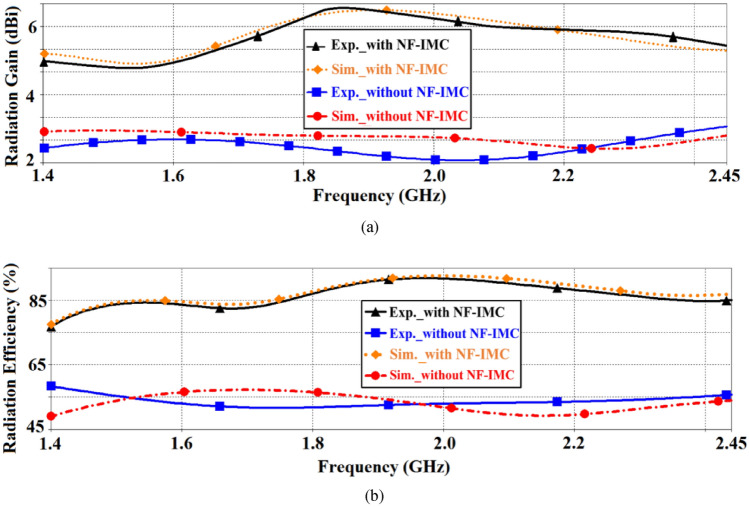
The simulated and measured radiation gain and efficiency in the xy-plane (E-plane) of the proposed antenna before and after applying NF-IMC are shown in Fig. 11. There is good correlation between the simulated and measured results. It is evident from these results that with NF-IMC the measured radiation gain increases by 3.2 dBi from an average of 2.4 dBi to 5.6 dBi across 1.4–2.45 GHz. Over the same frequency span the measured radiation efficiency of the antenna increased by 31.5% from an average of 54.5% to 86%.
Figure 11.
Simulated and measured radiation properties of the proposed CRLH-TL antenna with and without NF-IMC in the xy-plane, (a) gain, and (b) efficiency.
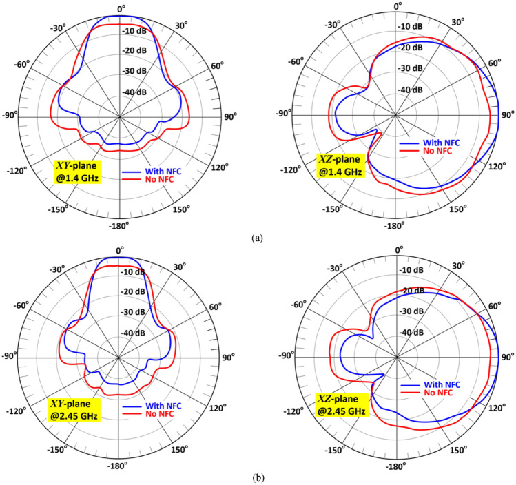
Figure 12 shows how the current density is distributed over the surface of the antenna at various frequencies in its operating frequency band. It reveals the magnitude of the current is strongest over the middle two and outer unit-cells. The measured 2D radiation patterns of the antenna in the xy-plane (E-plane) and xz-plane (H-plane) with and without NF-IMC at 1.4 GHz and 2.45 GHz are shown in Fig. 13. The antenna’s radiation energy is mainly focused in the x-direction. The beamwidth is much narrower in the xy-plane (E-plane).
Figure 12.
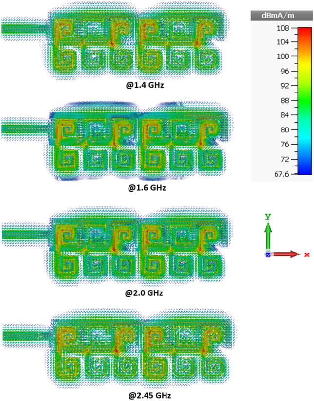
Current density distributions over the proposed antenna at spot frequencies of 1.4 GHz, 1.6 GHz, 2.0 GHz, and 2.45 GHz.
Figure 13.
Measured radiation patterns (normalized) of the antenna without and with NF-IMC in the xy-plane (E-plane) and xz-plane (H-plane) at (a) 1.4 GHz and (b) 2.45 GHz.
The performance of the proposed CRLH-TL antenna with NF-IMC is compared with other state-of-the-art antennas reported in literature. The results of this study are summarized in Table 3. The main advantages of the proposed work are its simplicity and stability over a very wide (> 1 GHz) operating frequency range.
Table 3.
Performance Comparison Between the Proposed Work and Prior Arts.
| References | FBW (%) [Freq. range] | Measured Gain (dBi) | Size (mm3) | NF-IMC topology |
|---|---|---|---|---|
| 18 | 4.9 [400-420 MHz] | 1.05 | Not given | Relatively simple |
| 19 | 25.6 [85–110 MHz] | 3 | 73 × 50 × 1.6 | Relatively simple |
| 20 | 66.7 [80–160 MHz] | 3 | 20 × 20 × 0.5 | Requires 4 transistors |
| 21 | 3.6 [1.35–1.45 GHz] | Not given | 70 × 48 × 0.5 | Requires transversal filter using distributed amplifiers & delay lines |
| 22 | 20 [1.0–1.5 GHz] | 5 | 12 × 12 × 1 | Requires four transistors |
| 23 | 26.1 [100–130 MHz] | Not given | Not given | Relatively simple |
| This work | 54.5 [1.4–2.45 GHz] | 6.55 | 56 × 20 × 0.8 | Relatively simple |
Conclusions
It has been shown that by incorporating a non-Foster impedance matching circuit (NF-IMC) in-line with a miniature antenna, which is based on composite right/left-handed transmission-line technology, the operating bandwidth and radiation gain of the antenna can be substantially enhanced without affecting the antenna’s stability. This is because the negative reactance generated by the NF-IMC is used to counteract the input capacitance of the antenna. The results presented demonstrate the effectiveness of this technique where the antenna’s bandwidth is shown to increase from 380 MHz to greater than 1 GHz. Moreover, by incorporating the NF-IMC the average radiation gain and efficiency are shown to improve by 3.2 dBi and 31.5% over its operating bandwidth.
Acknowledgements
This work is partially supported by RTI2018-095499-B-C31, Funded by Ministerio de Ciencia, Innovación y Universidades, Gobierno de España (MCIU/AEI/FEDER,UE), and innovation programme under grant agreement H2020-MSCA-ITN-2016 SECRET-722424 and the financial support from the UK Engineering and Physical Sciences Research Council (EPSRC) under grant EP/E022936/1.
Author contributions
Conceptualization, M.A., B.S.V., C.H.S., R.A.A.-A., F.F., I.H., T.A.D., and E.L.; methodology, M.A., B.S.V., F.F., I.H., T.A.D., and E.L.; software, M.A., B.S.V., and C.H.S.; validation, M.A., B.S.V., A.A.A., L.A., N.O.P., C.H.S., R.A.A.-A., F.F., I.H., T.A.D., and E.L.; formal analysis, M.A., B.S.V., C.H.S., R.A.A.-A., F.F., I.H., T.A.D., and E.L.; investigation, M.A., B.S.V., C.H.S., R.A.A.-A., F.F., I.H., T.A.D., and E.L.; resources, M.A., B.S.V., C.H.S., R.A.A.-A., F.F., I.H., T.A.D., and E.L.; data curation, M.A., B.S.V., A.A.A., L.A., N.O.P., C.H.S., R.A.A.-A., F.F., I.H., T.A.D., and E.L.; writing—original draft preparation, M.A.; writing—review and editing, M.A., B.S.V., A.A.A., L.A., N.O.P., C.H.S., R.A.A.-A., F.F., I.H., T.A.D., and E.L.; visualization, M.A., B.S.V., C.H.S., R.A.A.-A., F.F., I.H., T.A.D., and E.L.; supervision, E.L.; project administration, R.A.A.-A., F.F., and E.L.; funding acquisition, R.A.A.-A., F.F, E.L.
Competing interests
The authors declare no competing interests.
Footnotes
Publisher's note
Springer Nature remains neutral with regard to jurisdictional claims in published maps and institutional affiliations.
References
- 1.Nandi S, Mohan A. CRLH unit cell loaded quad-band monopole antenna. Microwave Opt. Tech. Lett. 2016;58(3):653–658. doi: 10.1002/mop.29636. [DOI] [Google Scholar]
- 2.Kim S, Lee J. Frequency and bandwidth of the negative/positive nth mode of a composite right-/left-handed transmission line. J. Electromagn. Eng. Sci. 2018;18:1–6. doi: 10.26866/jees.2018.18.1.1. [DOI] [Google Scholar]
- 3.Nelaturi S, Sarma N. A compact microstrip patch antenna based on metamaterials for WiFi and WiMAX application. J. Electromagn. Eng. Sci. 2018;18:182–187. doi: 10.26866/jees.2018.18.3.182. [DOI] [Google Scholar]
- 4.Yuan Y, Zhang K, Ratni B, Song Q, Ding X, Wu Q, Burokur SN, Genevet P. Independent phase modulation for quadruplex polarization channels enabled by chirality-assisted geometric-phase metasurfaces. Nat. Commun. 2020;11:4186. doi: 10.1038/s41467-020-17773-6. [DOI] [PMC free article] [PubMed] [Google Scholar]
- 5.Zhang K, Yuan Y, Ding X, Li H, Ratni B, Wu Q, Liu J, Burokur SN, Tan J. Polarization-engineered non interleaved metasurface for integer and fractional orbital angular momentum multiplexing. Laser Photon. Rev. 2021 doi: 10.1002/lpor.202000351. [DOI] [Google Scholar]
- 6.Yuan Y, Sun S, Chen Y, Zhang K, Ding X, Ratni B, Wu Q, Burokur SN, Qiu C-W. A fully phase-modulated metasurface as an energy-controllable circular polarization router. Adv. Sci. 2020;7(18):2001437. doi: 10.1002/advs.202001437. [DOI] [PMC free article] [PubMed] [Google Scholar]
- 7.Caloz C, Itoh T. Electromagnetic Metamaterials: Transmission Line Theory and Microwave Applications. Wiley-IEEE Press; 2005. [Google Scholar]
- 8.Zhang J, Yan S, Vandenbosch GAE. Realization of dual-band pattern diversity with a CRLH-TL-inspired reconfigurable metamaterial. IEEE Trans. Antennas Propag. 2018;66(10):5130–5138. doi: 10.1109/TAP.2018.2859917. [DOI] [Google Scholar]
- 9.Lee H, Ren D, Choi JH. Dual-band and polarization-flexible CRLH substrate-integrated waveguide resonant antenna. IEEE Antennas Wireless Propag. Lett. 2018;17(8):1469–1472. doi: 10.1109/LAWP.2018.2849678. [DOI] [Google Scholar]
- 10.Gupta A, Chaudhary RK. ‘A miniaturized dual-band ZOR antenna using epsilon negative transmission line loading’. Int. J. Microw. Wireless Technol. 2017;9(8):1735–1739. doi: 10.1017/S175907871700040X. [DOI] [Google Scholar]
- 11.Khan MS, Capobianco A-D, Iftikhar A, Asif S, Ijaz B, Braaten BD. A frequency-reconfigurable series-fed microstrip patch array with interconnecting CRLH transmission lines. IEEE Antennas Wireless Propag. Letters. 2016;15:242–245. doi: 10.1109/LAWP.2015.2439637. [DOI] [Google Scholar]
- 12.Shih T-Y, Behdad N. Wideband, non-Foster impedance matching of electrically small transmitting antennas. IEEE Trans. Antennas Propag. 2018;66(11):5687–5697. doi: 10.1109/TAP.2018.2863123. [DOI] [Google Scholar]
- 13.Kim T-H, Yun G-H, Lee W, Yook J-G. Highly efficient WPT system with negative impedance converter for Q-factor improvement. IEEE Access. 2019;7:108750–108760. doi: 10.1109/ACCESS.2019.2933004. [DOI] [Google Scholar]
- 14.White CR, Colburn JS, Nagele RG. A non-Foster VHF monopole antenna. IEEE Antennas Wirel. Propag. Lett. 2012;11:584–587. doi: 10.1109/LAWP.2012.2201129. [DOI] [Google Scholar]
- 15.Go J-G, Chung J-Y. Non-Foster matching circuit design to improve VHF and UHF-band small antenna impedance matching. J. Korean Inst. Electromagn. Eng. Sci. 2018;29:159–166. doi: 10.5515/KJKIEES.2018.29.3.159. [DOI] [Google Scholar]
- 16.Linvill JG. Transistor negative impedance converters. Proc. IRE. 1953;41(6):725–729. doi: 10.1109/JRPROC.1953.274251. [DOI] [Google Scholar]
- 17.Kou N, Shi Y, Li L. New equivalent circuit analysis and synthesis for broadband composite right/left-handed transmission line metamaterials. ACES J. 2016;31:884–893. [Google Scholar]
- 18.Shi T, Tang M-C, Wu Z, Xu H-X, Ziolkowski RW. Improved signal-to-noise ratio, bandwidth-enhanced electrically small antenna augmented with internal non-foster elements. IEEE Trans. Antennas Propag. 2019;67(4):2763–2768. doi: 10.1109/TAP.2019.2894331. [DOI] [Google Scholar]
- 19.Shen, Y. & Chio, T. Matching electrically small antenna using non-Foster circuit in the FM-band. The 8th Europ. Conf. on Ant. & Propag. (EuCAP 2014), The Hague, 2014, pp. 333–336.
- 20.Albarracín-Vargas F, et al. Design method for actively matched antennas with non-Foster elements. IEEE Trans. Ant. Propag. 2016;64(9):4118–4123. doi: 10.1109/TAP.2016.2583482. [DOI] [Google Scholar]
- 21.Zhang T, et al. Unconditionally stable non-foster element using active transversal-filter-based negative group delay circuit. IEEE Microw. Wirel. Comp. Lett. 2017;27(10):921–923. doi: 10.1109/LMWC.2017.2745487. [DOI] [Google Scholar]
- 22.Batel, L., Pintos, J. & Rudant, L. Superdirective and broadband compact antenna array using non-Foster elements. Int. Workshop on Antenna Technology (iWAT), Miami, FL, USA, 2019, pp.17–20.
- 23.Jacob MM, et al. Non-Foster matched antennas for high-power applications. IEEE Trans. On Ant. Propag. 2017;65(9):4461–4469. doi: 10.1109/TAP.2017.2727513. [DOI] [Google Scholar]


