Abstract
Objectives
To compare the transfer accuracy of two digital transfer trays, the three-dimensional printed (3D printed) tray and the vacuum-formed tray, in the indirect bonding of labial brackets.
Materials and Methods
Ten digital dental models were constructed by oral scans using an optical scanning system. 3D printed trays and vacuum-formed trays were obtained through the 3Shape indirect bonding system and rapid prototyping technology (10 in each group). Then labial brackets were transferred to 3D printed models, and the models with final bracket positioning were scanned. Linear (mesiodistal, vertical, buccolingual) and angular (angulation, torque, rotation) transfer errors were measured using GOM Inspect software. The mean transfer errors and prevalence of clinically acceptable errors (linear errors of ≤0.5 mm and angular errors of ≤2°) of two digital trays were compared using the Mann-Whitney U-test and the Chi-square test, respectively.
Results
The 3D printed tray had a lower mean mesiodistal transfer error (P < .01) and a higher prevalence of rotation error within the limit of 2° (P = .03) than did the vacuum-formed tray. Linear errors within 0.5 mm were higher than 90% for both groups, while torque errors within 2° were lowest at 50.9% and 52.9% for the 3D printed tray and vacuum-formed tray, respectively. Both groups had a directional bias toward the occlusal, mesial, and buccal.
Conclusions
The 3D printed tray generally scored better in terms of transfer accuracy than did the vacuum-formed tray. Both types of trays had better linear control than angular control of brackets.
Keywords: Indirect bonding, Bracket, Transfer accuracy, 3D printed tray, Vacuum-formed tray
INTRODUCTION
In the 1970s, Silverman et al.1 first proposed the concept of indirect bonding, in which brackets were first positioned on the dental model with cement and then transferred to the patient's teeth by an individual transfer tray. However, this method never achieved mass adoption because of the limitations of the hardware materials and complicated procedures. Today, as a result of the advancement of straight-wire appliances and the adoption of lingual orthodontics, accuracy requirements of bracket positions are becoming more stringent, and indirect bonding is gaining popularity because of the unimpaired visibility it affords during bracket positioning, its reduced chair time, and improved patient comfort.2–5
The bracket transfer step is critical to ensure high accuracy in indirect bonding and is affected by the doctor's experience, tray material characteristics, and other factors. The traditional laboratory process of making transfer trays usually uses materials such as silicone or thermoplastic that include an inner ethyl vinyl acetate sheet and an outer polyethylene terephthalate glycol sheet. Several studies6–8 found that silicone-based trays resulted in higher transfer accuracy. As technology advanced, a series of digitalized indirect bonding systems appeared.9–11 These systems allowed orthodontists to simulate the process of aligning teeth, positioning brackets, and designing transfer trays while also precisely and efficiently three-dimensionally (3D) printing customized trays through rapid prototyping technology. While there are already cases involving use of 3D printed transfer trays in patient care, there has been little academic research on the accuracy of this technology.12–16 In this study, the indirect bonding procedure was digitalized by the 3Shape indirect bonding system, and the transfer accuracy of 3D printed trays was compared with that of the double vacuum-formed trays made from 3D printed models.
MATERIALS AND METHODS
Fabrication of Digital and Physical Models
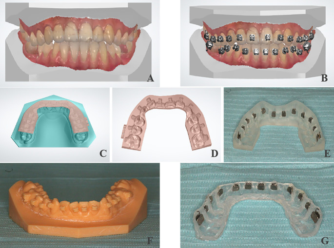
Ten digital dental models were constructed by oral scans using the Trios optical scanning system (3Shape, Copenhagen, Denmark) (Figure 1A). The models had permanent dentition with mild crowding of less than 4 mm. A 3D printer (UltraCraft A2, HeyGears, Guangzhou, Guangdong, China) printed two physical models for each digital version by digital light-processing technology for a total of 20 3D printed light-curing resin models. OrthoAnalyzer™ software (3Shape) was used to simulate tooth alignment, and then, using the MBT bracket height positioning method, standard torque DamonQ brackets (Ormco, Glendora, Calif) and Snaplink buccal tubes (Ormco) selected from the bracket database were positioned from the incisors to the first molars.17 Once the bracket and buccal tube positions were fixed on the digital model, the model was returned to the original set-up to obtain digital model M1 with the positioned brackets (Figure 1B).
Figure 1.
Fabrication of two kinds of trays: (A) digital dental model via oral scanning; (B) positioning brackets digitally; (C and D) designing the digital transfer tray; (E) 3D printed transfer tray; (F) 3D printed model with positioned brackets; and (G) double vacuum-formed tray.
Fabrication of 3D Printed Trays
First, ApplianceDesigner™ software (3Shape) was applied to the M1 model to design a digital transfer tray with the following rules: buccal extending until below the bracket and below the buccal tube, lingual covering half of the lingual surface until the distal marginal ridge of the first molars, with a thickness of 1.5 mm. Then, E-IDB 3D printing raw materials made from photocurable resin were used to print the transfer trays with a desk 3D printer (Perfactory Vida, Envision TEC, Gladbeck, Nordrhein-Westfalen, Germany) through digital light-processing technology (Figure 1C–E).
Fabrication of Double Vacuum-Formed Trays
Ten digital models M1 with positioned brackets were printed by the 3D printer (UltraCraft A2, HeyGears) using digital light-processing technology. Then the transparent double vacuum-formed transfer tray was made using a pressure molding machine (Ministar, Scheu, Iserlohn, Nordrhein-Westfalen, Germany), vacuum forms, and the 3D printed model. The inside layer was a soft, 2-mm plastic vacuum form (Bioplast® bleach, Scheu) that was heated for 50 seconds; the outside layer was a hard, 1.5-mm plastic vacuum form (Duran®, Scheu) that was heated for 50 seconds. The cutting edge was the same as that of the 3D printed transfer tray (Figure 1F,G).
Bracket Transfer In Vitro
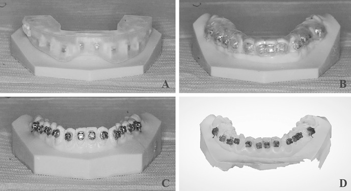
The two types of trays were fitted to 20 resin models and checked for alignment. Standard torque DamonQ brackets and Snaplink buccal tubes were inserted into the tray. Primer (Grengloo™, Ormco) and resin glue (Grengloo™, Ormco) were used for indirect bonding. The tray was seated over the model, and the resin was cured from the gingival and occlusal sides for 30 seconds each using a curing light (Bluephase N MC, Ivoclar Vivadent, Schaan, Liechtenstein) and without vertical finger pressure. Afterward, the transfer trays were removed carefully, and the excess resin around the brackets and buccal tubes was removed using a round bur at low speed. Lastly, the model with the transferred brackets was scanned using the 3Shape Trios optical scanning system to obtain digital model M2 (Figure 2A–D).
Figure 2.
Indirect bonding in vitro: (A) indirect bonding by 3D printed tray in vitro; (B) indirect bonding by vacuum-formed tray in vitro; (C) 3D printed model with transferred brackets; and (D) digital dental model with transferred brackets obtained by oral scanning.
Transfer Error Measurements
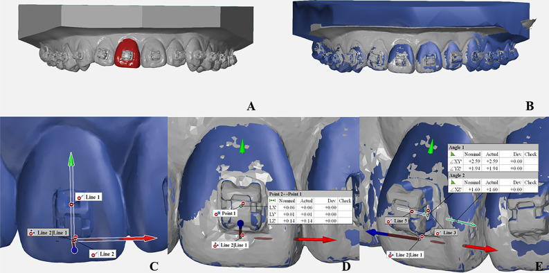
The data for model M1, which had positioned brackets, and model M2, which had transferred brackets, were exported from OrthoAnalyzer™ software. The STL files were loaded into GOM Inspect 2018 software (GOM, Braunschweig, Lower Saxony, Germany). The prealignment function was first used to superimpose the scanned models M2 and M1, followed by the local best-fit function, which was performed to superimpose the selected tooth on M2 with the corresponding tooth on M1 (excluding the measured bracket). The tooth's long axis was positioned on the Y-axis, and the direction perpendicular to the tooth's buccal surface was positioned on the Z-axis, with the spatial 3D coordinate system extended for each tooth. The differences between each tooth's bracket or buccal tube predicted and actual positions on the 3D coordinate system in the linear (mesiodistal, vertical, buccolingual) and angular (angulation, torque, rotation) dimensions were calculated (Figure 3A–E).
Figure 3.
Measuring transfer errors of two kinds of trays: (A and B) superimposing the scanned models M2 and M1 using the local best-fit function of GOM Inspect 2018 software; (C) establishing the spatial 3D coordinate system for each tooth; and (D and E) calculating the linear (mesiodistal, vertical, buccolingual) and angular (angulation, torque, rotation) transfer errors on the 3D coordinate system of each tooth.
Statistical Analysis
Two weeks after the initial measurement, the same person conducted a repeat measurement on one randomly selected digital model with transferred brackets and calculated the linear and angular measurement errors using Dahlberg's formula.
The Mann-Whitney U-test and the Chi-square test were used to compare the mean transfer errors and the prevalence of clinically acceptable transfer errors, respectively, in the two groups. Based on the American Board of Orthodontics objective grading system, when the alignment of marginal ridges exceeds 0.5 mm, models receive higher OGS scores. Additionally, a crown-tip inadequacy of 2° causes a marginal ridge discrepancy of 0.5 mm in an average-sized molar.18,19 Therefore, linear errors of ≤0.5 mm and angular errors of ≤2° were used as the criteria. Next, all teeth were divided into four groups (incisors, canines, premolars, and molars), and the Kruskal-Wallis test was applied to test for the overall difference of transfer errors among tooth groups, followed by multiple pairwise comparisons with Dunn-Bonferroni post hoc tests. Significance was defined as P < .05. SPSS version 24.0 (IBM, Armonk, NY) was used for the statistical analysis.
RESULTS
Dahlberg's formula calculation results showed a 0.02-mm measurement error in the mesiodistal direction, 0.02 mm vertically, 0.01 mm buccolingually, 0.52° in angulation, 0.32° torque, and 0.61° rotation.
The mean mesiodistal error of the 3D printed tray group was significantly lower than that of the vacuum-formed tray group (P < .01) (Table 1), and the prevalence of rotation error within 2° was higher than that of the vacuum-formed tray group (P = .03) (Table 2). The two groups' prevalences of linear errors within 0.5 mm were all higher than 90%, with the 3D printed tray group reaching 100% mesiodistally, while the prevalence of torque error within 2° was lowest at 50.9% and 52.9% for the 3D printed tray and vacuum-formed tray, respectively, followed by angulation errors at 57.4% and 65.4% and rotation errors at 85.2% and 73.1% (Table 2).
Table 1. .
Comparison of Mean Transfer Errors Between the Two Transfer Tray Groupsa
| Section |
Mean ± SD |
P-Value |
|
| 3D Printed Transfer Tray (n = 108) |
Vacuum-Formed Transfer Tray (n = 104) |
||
| Mesiodistal, mm | 0.07 ± 0.06 | 0.10 ± 0.10 | .00** |
| Vertical, mm | 0.19 ± 0.20 | 0.23 ± 0.19 | .06 |
| Buccolingual, mm | 0.13 ± 0.15 | 0.10 ± 0.12 | .08 |
| Angulation, ° | 2.25 ± 1.97 | 1.86 ± 1.72 | .27 |
| Torque, ° | 3.14 ± 2.91 | 3.09 ± 2.78 | .83 |
| Rotation, ° | 1.22 ± 0.90 | 1.44 ± 1.05 | .17 |
Mann-Whitney U-test indicated that there was a significant difference between the two groups' mean transfer errors in mesiodistal direction (P < .01).
P < .01.
Table 2. .
Comparison of Prevalence of Clinically Acceptable Errors Between the Two Transfer Tray Groupsa
| Section |
3D Printed Transfer Tray (n = 108) |
Vacuum-Formed Transfer Tray (n = 104) |
χ2 |
P-Value |
| Mesiodistal, % | 100.0 | 99.0 | 1.04 | .31 |
| Vertical, % | 96.3 | 91.4 | 2.26 | .13 |
| Buccolingual, % | 95.4 | 97.1 | 0.44 | .51 |
| Angulation, % | 57.4 | 65.4 | 1.42 | .23 |
| Torque, % | 50.9 | 52.9 | 0.08 | .78 |
| Rotation, % | 85.2 | 73.1 | 4.72 | .03* |
Chi-square (χ2) test indicated that there was a significant difference between the two groups' prevalences of clinically acceptable rotation error (P < .05).
P < .05.
The 3D printed tray group and vacuum-formed tray group had transfer errors biased toward the occlusal at 79.6% and 93.3%, respectively; toward the mesial at 61.1% and 87.5%, respectively; and toward the buccal at 73.2% and 61.5%, respectively, and there were no obvious directional trends for angular errors (Table 3).
Table 3. .
Percentages of Frequency of Directional Bias Resulting in the Two Transfer Tray Groupsa
| Group |
Total, No. |
Dimension |
|||||||||||
| Mesiodistal, % |
Vertical, % |
Buccolingual, % |
Angulation, % |
Torque, % |
Rotation, % |
||||||||
| + |
− |
+ |
− |
+ |
− |
+ |
− |
+ |
− |
+ |
− |
||
| 3D printed transfer tray | 108 | 61.1 | 38.9 | 79.6 | 20.4 | 73.2 | 26.9 | 38.9 | 61.1 | 44.4 | 55.6 | 59.3 | 40.7 |
| Vacuum-formed transfer tray | 104 | 87.5 | 12.5 | 93.3 | 6.7 | 61.5 | 38.5 | 54.8 | 45.2 | 46.2 | 53.9 | 44.2 | 55.8 |
“+” Represents a final bracket position more mesial, buccal, or occlusal, or with more buccal crown torque, more mesial tip, or a facial surface rotated more mesially than predicted. “−” represents the reverse.
For the 3D printed tray group, the differences between tooth groups were nonsignificant. For the vacuum-formed tray group, molars showed significantly greater transfer error for angulation than did incisors and premolars (P < .01) (Figures 4 through 7).
Figure 4.
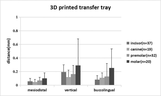
Comparison of mean linear transfer errors by tooth type in the 3D printed transfer tray group.
Figure 7.
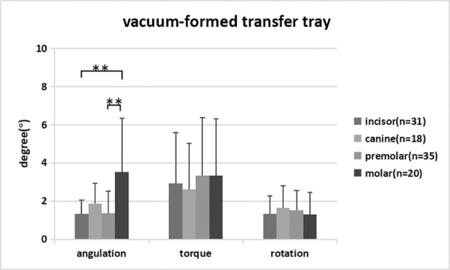
Comparison of mean angular transfer errors by tooth type in the vacuum-formed transfer tray group. ** P < .01.
Figure 5.
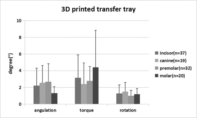
Comparison of mean angular transfer errors by tooth type in the 3D printed transfer tray group.
Figure 6.
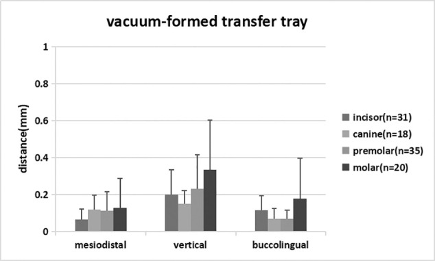
Comparison of mean linear transfer errors by tooth type in the vacuum-formed transfer tray group.
DISCUSSION
In this study, 240 brackets were bonded in total, 27 of which debonded and one of which inverted. Of the remaining brackets, 108 brackets were measured for the 3D printed tray group, and 104 were measured for the vacuum-formed tray group. Based on the data in Tables 1 and 2, the 3D printed tray made from E-IDB printing materials was more accurate than was the vacuum-formed tray in terms of the mean mesiodistal error and the prevalence of rotation error within 2°, which may have been due to the high printing precision of transfer trays and the hard, inelastic characteristic of the printing materials. In addition, the data indicated that both groups had better linear control than angular control of the brackets. Similar results have been shown in experiments8,20,21 studying other indirect bonding techniques. One possible reason was that the torque and rotation were affected by the consistency of the bonding resin adhesive between the bracket base and the tooth surface. Another possible reason for this difference in control was that the design of the 3D printed tray in the experiment may have contributed to the result. To reduce the likelihood of cracking when embedding brackets in the tray, which happened during preliminary experiments as a result of insufficient strength of the tray, the fully enclosed 3D printed transfer tray was later changed to a semienclosed design that covered the two sides and occlusal surface of the bracket but not the gingival and undercut surfaces. However, the new design might have weakened the control of the bracket positioning in three dimensions. This result suggested that orthodontists must apply resin consistently during indirect bonding to reduce angular transfer errors and that the design and material of 3D printed trays require further improvements.
Transfer errors for both groups had a directional bias toward the occlusal vertically, especially the vacuum-formed tray, in which the bias was as high as 93.3%. This result was consistent with the findings by Dörfer et al.6 and Castilla et al.7 This occurrence was likely caused by incomplete seating of the tray due to a slight misalignment between the bracket and transfer tray, and a lack of vertical pressure on the tray during the light-curing process of the experiment. Appropriate pressure would help to improve the seating of the tray, while too much pressure could also make the brackets shift in the gingival direction. Therefore, orthodontists should adjust the pressure accordingly based on the tray material. The transfer error was also biased toward the mesial and buccal directions. The mesial bias is yet to be explained, but one hypothesis for the buccal bias was that the adhesive on the bracket base increased the thickness between the bracket base and the tooth surface. This result was consistent with findings from Schmid et al.8 and Grünheid et al.22
Most scholars18 believe that the posterior teeth have greater transfer errors in bracket position than do the anterior teeth, but this belief was not supported by the current data. One possible explanation was that there were no visibility issues because the experiment was conducted in vitro. In the vacuum-formed tray group, the angulation error of molars was significantly higher than that for incisors and premolars, possibly because the molar buccal hooks hindered the formation of retentive undercuts for buccal tubes under vacuum pressure.
The transfer accuracy of trays in the current study was determined by printing precision, material properties, tray design, and the orthodontists' operating skills. The numerical value of printing precision is the thickness of each printing layer; the smaller the numerical value of the print precision, the higher the printing quality. In this study, the transfer tray printer (Perfactory Vida, Envision TEC) had a high printing precision at 0.05 μm, which ensured the accuracy of the 3D printed tray. The printer (UltraCraft A2, HeyGears) had a printing precision for models of 50 μm, which affected the accuracy of the vacuum-formed tray but was eligible to meet clinical requirements based on existing clinical studies.23–25
There were also possible experimental errors related to digital scanning, bracket transfer skills, measurements, etc. The 3Shape Trios optical scanning system had a precision of 0.8 to approximately 1.2 μm and would be expected to have had minimal impact. The processes of bracket transfer and measuring transfer errors were performed by the same operator to eliminate potential variabilities from any skill differences, and two different operators participated to ensure blinding. The measurement software used in this experiment, GOM Inspect 2018, had an accuracy of 1 μm and could use the local best-fit function to superimpose each tooth pair accurately, which would have reduced the impact from the scanned soft tissue and the scanned dental arch, as previously described by Anh et al.26 The study's coefficient of variation was high and may have been related to an insufficient sample size. Increasing the sample size would have improved the reliability of the results.
The high bonding failure rate of more than 11% suggested that the indirect bonding protocol was very technique-sensitive, and it would require rebonding brackets directly, therefore resulting in increased chair time and reduced accuracy when operating in vivo. Orthodontists should keep practicing to improve their operating familiarity and skills to reduce the failure rate.
Based on the results of this experiment, the 3D printed tray was more accurate than the double vacuum-formed tray in the horizontal control of brackets and the prevalence of rotation error within 2°. However, since this was an in vitro experiment, in vivo operations might be influenced by additional factors that could result in greater errors, such as moisture control, soft tissue interference, and patient well-being. Additional studies are required to further validate the effectiveness of indirect bonding in vivo between the two transfer trays.
CONCLUSIONS
The 3D printed tray had a higher transfer accuracy than did the double vacuum-formed tray in the horizontal control of brackets and the prevalence of rotation error within 2°.
Both types of trays had better linear control than angular control of brackets.
The transfer errors for both types of trays showed a directional bias toward the occlusal, mesial, and buccal.
Molars had a greater angulation error than did incisors and premolars in the double vacuum-formed tray group.
REFERENCES
- 1. .Silverman E, Cohen M, Gianelly AA. A universal direct bonding system for both metal and plastic brackets. Am J Orthod. 1972;62:236–244. doi: 10.1016/s0002-9416(72)90264-3. [DOI] [PubMed] [Google Scholar]
- 2. .Thomas RG. Indirect bonding: simplicity in action. J Clin Orthod. 1979;13:93–106. [PubMed] [Google Scholar]
- 3. .White LW. A new and improved indirect bonding technique. J Clin Orthod. 1999;33:17–23. [PubMed] [Google Scholar]
- 4. .Hodge TM, Dhopatkar AA, Rock WP, Spary DJ. The Burton approach to indirect bonding. J Orthod. 2001;28:267–270. doi: 10.1093/ortho/28.4.267. [DOI] [PubMed] [Google Scholar]
- 5. .Kalange JT. Indirect bonding: a comprehensive review of the advantages. World J Orthod. 2004;5:301–307. [PubMed] [Google Scholar]
- 6. .Dörfer S, König M, Jost-Brinkmann P-G. Übertragungsgenauigkeit beim indirekten Platzieren von Brackets [in German] Kieferorthopädie. 2006;20:91–104. [Google Scholar]
- 7. .Castilla AE, Crowe JJ, Moses JR, Wang M, Ferracane JL, Covell DA. Measurement and comparison of bracket transfer accuracy of five indirect bonding techniques. Angle Orthod. 2014;84:607–614. doi: 10.2319/070113-484.1. [DOI] [PMC free article] [PubMed] [Google Scholar]
- 8. .Schmid J, Brenner D, Recheis W, Hofer-Picout P, Brenner M, Crismani AG. Transfer accuracy of two indirect bonding techniques—an in vitro study with 3D scanned models. Eur J Orthod. 2018;40:549–555. doi: 10.1093/ejo/cjy006. [DOI] [PubMed] [Google Scholar]
- 9. .Sachdeva R, Frugé JF, Frugé AM, et al. SureSmile: a report of clinical findings. J Clin Orthod. 2005;5:297–314. [PubMed] [Google Scholar]
- 10. .Gracco A, Tracey S. The insignia system of customized orthodontics. J Clin Orthod. 2011;45:442–451. [PubMed] [Google Scholar]
- 11. .Romano R, Geron S, Echarri P. Customized Brackets and Archwires Lingual and Esthetic Orthodontics 1st ed. London, UK: Quintessence Publishing; 2011. pp. 154–156. [Google Scholar]
- 12. .Ciuffolo F, Epifania E, Duranti G, Luca VD, Raviglia D, Rezza S. Rapid prototyping: a new method of preparing trays for indirect bonding. Am J Orthod Dentofacial Orthop. 2006;129:75–77. doi: 10.1016/j.ajodo.2005.10.005. [DOI] [PubMed] [Google Scholar]
- 13. .Son KH, Park JW, Lee DK, Kim KD, Baek SH. New virtual orthodontic treatment system for indirect bonding using the stereolithographic technique. Korean J Orthod. 2011;41:138–146. [Google Scholar]
- 14. .Yun L, Hong-ming G. A computer-aided indirect bonding system for lingual brackets. Beijing J Stomatol. 2009;17:220–222. [Google Scholar]
- 15. .Jing Z, Hong-ming G, Yu-xing B. Application of digital model in lingual indirect bonding. Chin J Orthod. 2010;17:127–130. [Google Scholar]
- 16. .Hui C, Hong-ming G, Yu-xing B, Song L. A comparison of virtual and actual bracket position orientated by CAD/CAM indirect bonding method. Beijing J Stomatol. 2012;20:270–273. [Google Scholar]
- 17. .McLaughlin RP, Bennett JC. Bracket placement with the preadjusted appliance. J Clin Orthod. 1995;29:302–311. [PubMed] [Google Scholar]
- 18. .Casko JS, Vaden JL, Kokich VG, et al. Objective grading system for dental casts and panoramic radiographs. Am J Orthod Dentofacial Orthop. 1998;114:589–599. doi: 10.1016/s0889-5406(98)70179-9. [DOI] [PubMed] [Google Scholar]
- 19. .Keating AP, Knox J, Bibb R, Zhurov AI. A comparison of plaster, digital and reconstructed study model accuracy. J Orthod. 2008;35:191–201. doi: 10.1179/146531207225022626. [DOI] [PubMed] [Google Scholar]
- 20. .Schubert K, Halbich T, Jost-Brinkmann PG, Müller-Hartwich R. Precision of indirect bonding of lingual brackets using the Quick Modul System (qms)®. J Orofac Orthop. 2013;74:6–17. doi: 10.1007/s00056-012-0122-z. [DOI] [PubMed] [Google Scholar]
- 21. .Kim J, Chun YS, Kim M. Accuracy of bracket positions with a CAD/CAM indirect bonding system in posterior teeth with different cusp heights. Am J Orthod Dentofacial Orthop. 2018;153:298–307. doi: 10.1016/j.ajodo.2017.06.017. [DOI] [PubMed] [Google Scholar]
- 22. .Grünheid T, Lee MS, Larson BE. Transfer accuracy of vinyl polysiloxane trays for indirect bonding. Angle Orthod. 2016;86:468–474. doi: 10.2319/042415-279.1. [DOI] [PMC free article] [PubMed] [Google Scholar]
- 23. .Kasparova M, Grafova L, Dvorak P, et al. Possibility of reconstruction of dental plaster cast from 3D digital study models. Biomed Eng OnLine. 2013;12:49. doi: 10.1186/1475-925X-12-49. [DOI] [PMC free article] [PubMed] [Google Scholar]
- 24. .Camardella LT, De VVO, Breuning H. Accuracy of printed dental models made with 2 prototype technologies and different designs of model bases. Am J Orthod Dentofacial Orthop. 2017;151:1178–1187. doi: 10.1016/j.ajodo.2017.03.012. [DOI] [PubMed] [Google Scholar]
- 25. .Kim SY, Shin YS, Jung HD, et al. Precision and trueness of dental models manufactured with different 3-dimensional printing techniques. Am J Orthod Dentofacial Orthop. 2018;153:144–153. doi: 10.1016/j.ajodo.2017.05.025. [DOI] [PubMed] [Google Scholar]
- 26. .Anh JW, Park JM, Chun YS, Kim M, Kim M. A comparison of the precision of three-dimensional images acquired by 2 digital intraoral scanners: effects of tooth irregularity and scanning direction. Korean J Orthod. 2016;46:3–12. doi: 10.4041/kjod.2016.46.1.3. [DOI] [PMC free article] [PubMed] [Google Scholar]


