

Abstract
Nuclear magnetic resonance (NMR) probes using thin-film HTS coils offer high sensitivity and are particularly suitable for small-sample applications. Typically, HTS probes are optimized for the detection of multiple nuclei and require several coils to be located within a small volume near the sample. Coupling between the coils shifts coil resonances and complicates coil trimming when tuning HTS probes. We have modeled the magnetic coupling between the coils of a 1.5-mm all-HTS NMR probe with 13C, 1H, and 2H channels. By measuring the magnetic coupling coefficients between individual coils, we solve the general coupling matrix given by KVL for six coupled resonators. Our results indicate that required trims can be accurately predicted by applying single coil trimming simulations to this magnetic coupling model. Use of the magnetic coupling model significantly improves the efficiency of tuning HTS probes.
1. Introduction
Nuclear magnetic resonance (NMR) is a powerful molecular characterization technique useful for the study of solution samples in biology, biochemistry, and organic chemistry. NMR utilizes the radiofrequency (RF) signals generated by isotopes with unpaired nuclear spins when located in a magnetic field and excited with an RF pulse. Due to its widespread abundance and relatively strong NMR signal, 1H is the most commonly employed isotope for NMR detection. However, 13C detection provides direct information concerning the carbon scaffolding that forms biological molecules and is also widely applied in NMR experiments despite its relatively low sensitivity and 1.1% natural abundance [1]. NMR notoriously suffers from a low detection sensitivity because of the low Boltzmann polarization available at temperatures suitable for biological samples. Improving the signal-to-noise ratio (SNR) in NMR spectra can be effectively accomplished by enhancing the sensitivity of the NMR probe. The SNR of a probe for a given sample can be described by
| (1) |
where M0 is the sample magnetization, B1/I is the strength of the RF excitation pulse per unit current in the coil, Tc, Ta, and Ts are the coil, preamplifier and sample noise temperatures, respectively, and Rs and Rc are the effective resistance of the sample and coil [2]. Cryogenic probes in which a normal metal coil is cooled to reduce Tc and Rc, and the preamplifier is cooled to reduce Ta, are widely used to improve sensitivity in NMR. Such probes are most effective when other terms, particularly the product of sample resistance and temperature TsRs, do not dominate the denominator. Cryogenic probes based on normal metal technology typically enable 3–4 times the detection sensitivity of conventional room temperature probes and preamplifiers [2–4].
Thin-film high temperature superconducting (HTS) RF coils in cryogenically cooled NMR probes can further improve SNR by reducing the coil resistance Rc beyond what can be achieved in a normal metal coil [1,5–8]. However, HTS coils have yet to be widely implemented in commercial NMR probes. Part of the reason may be that HTS probe construction is a tedious and time-consuming process. Variability in substrate thickness and photolithographic processes lead to differences in resonance frequency between coils of the same design even from the same wafer. In addition, the resonance frequency of an HTS coil is very sensitive to the local environment and is shifted by the presence of nearby conducting and even dielectric objects, particularly including other HTS resonators if present. Coil resonance frequencies often must be adjusted after fabrication. The resonances can be shifted by removing superconducting material through photolithography or with a laser [9]. For an interdigital capacitor the fingers can be shortened or removed to reduce the total capacitance, whereas for a transmission line resonator the structure can be shortened to reduce the electrical length. In either case the resonance frequency is shifted up. In this process, which we call trimming, it is not necessary to remove all excess material. Instead we separate small portions of the coil structure which then no longer participate in the resonant mode. The resonance can also be shifted down by coating the resonators with a dielectric material having a low loss tangent [10]. Testing and iteratively trimming/coating devices to achieve the required resonances for several channels simultaneously can be a time-consuming process, so it would be helpful to have tool to better predict the outcomes and reduce the number of iterative steps required.
The experiments outlined in this project were aimed to develop a model to effectively describe the behavior of a set of HTS resonators in order to increase the efficiency of the build-out process of HTS probes. A set of electromagnetic (EM) interactions in an ensemble of HTS resonators is related to setting the final frequencies of each channel of an HTS probe. While these interactions are largely magnetic, it wasn’t known if a simple magnetic coupling model would suffice to describe them or if there were significant electric interactions as well. This project utilizes RF/microwave filter theory based on coupling coefficients of intercoupled resonators to develop a model of the magnetic interactions between adjacent HTS coils [11]. The model has fairly general applicability since it was not based on a precise resonator material or design. We hypothesized that the magnetic coupling coefficients would remain relatively constant as resonator modes shifted during trimming. If magnetic coupling comprised the bulk of coil interactions, this method, used in conjunction with detailed EM simulations of each resonator, would predict the coupled modes of a multi-channel HTS NMR probe and make single-trim tuning procedures possible.
2. Materials and Method
All measurements were conducted on a 13C optimized 1.5-mm all-HTS NMR probe in development for a nominally 600 MHz NMR spectrometer. At the magnet’s field of 14.095 T, isotopes 13C, 1H, and 2H have Larmor frequencies of 150.903 MHz, 600.130 MHz, and 92.124 MHz, respectively. The 2H channel functions as a lock system to ensure the spectrometer operates at a constant net magnetic field [12]. The probe has a sample fill volume of about 35 microliters and active volume of about 20 μl. A probe of similar design previously developed in our lab is described in [1]. The probe described in [1] had a 13C channel quality factor (Q) of 2,200. The probe in development is intended to have an even more sensitive 13C channel. At zero applied field the new 13C coil has a Q of 34,000.
The probe featured three pairs of HTS coils in a Helmholtz-like configuration (Figure 1). Each of the six individual coils was patterned by Star Cryoelectronics (Santa Fe, NM, USA) from ~300 nm-thick films of Y1Ba2Cu3O7-δ (YBCO) coated epitaxially onto 430 μm-thick sapphire by Ceraco, GmBH (Ismaning, Germany). The 13C detection coils utilized a double-sided counter-wound spiral resonant structure consisting of four turns per side. The full details of the 13C coil will be published when the new probe is complete. A single-sided interdigital-capacitor based design, known as a racetrack design, with 24 fingers and four gaps was used for the 1H detection coils [13]. The 2H detection coils employed a single-sided spiral resonant structure with 10 turns. Evenly spaced tick marks prepared along the inner and outer edges of each coil trace served as a reliable independent variable while trimming. Trimming was accomplished via laser ablation. A 532-nm laser mounted on a microscope probe station was used to accurately and effectively eliminate portions of YBCO and increase the resonance frequency of the coil (Figure 2). Three movable normal metal power-matching loops were inductively coupled to the HTS coils and adjusted to minimize the reflection coefficient S11 at the relevant modes. A vector network analyzer (VNA) was used to measure the reflected response in continuous wave (CW) mode at 0 dBm incident power. Several HTS probes have implemented movable inductive tuning loops that give users the ability to finely tune coil resonances during routine probe use [1,5,14,15]. Normal metal tuning loops will be added later in probe development but were not present for these tests. All measurements were performed at a coil temperature of approximately 40 K, well under the superconducting transition temperature of YBCO (93 K).
Figure 1.

Design of the 1.5-mm all-HTS NMR probe. The details and dimensions are simplified or distorted for illustrative purposes and are not exact reproductions of the design. (a) Diagram of the NMR probe-head illustrating the arrangement of two pairs of HTS coils and the corresponding normal metal power-matching and tuning loops. (b) Cross-sectional schematic of the coil arrangement. Three Helmholtz-like pairs are maintained under vacuum at 40 K and surround the 1.5-mm sample tube. (c) Diagram of the coupling interactions present in an ensemble of resonators. The magnetic coupling coefficients Knm between each resonator construct the n × m coupling matrix used to predict the coupled modes.
Figure 2.
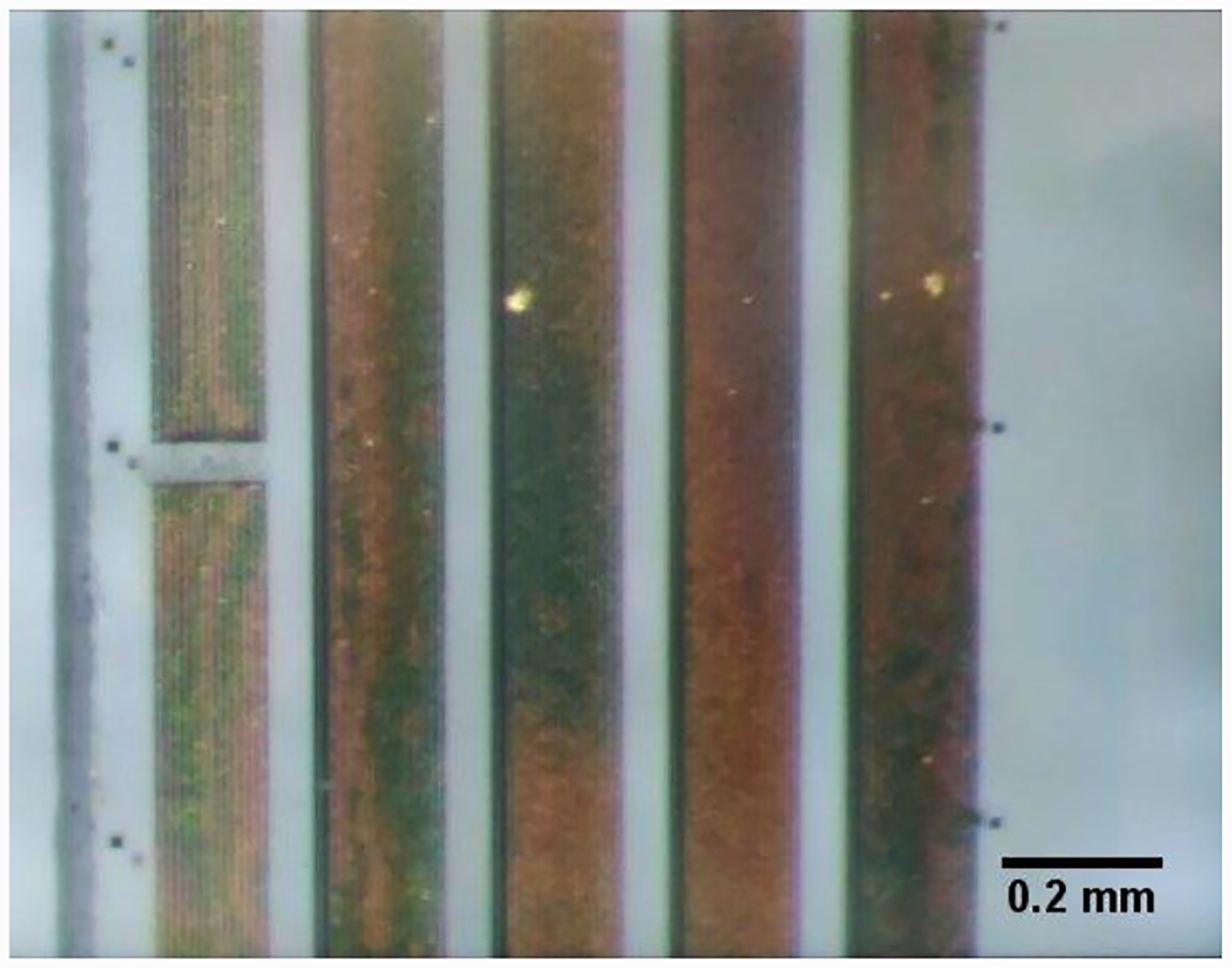
Visual results of laser ablation on a 13C detection HTS coil. A 532-nm laser mounted on a microscope probe station was used to trim the coils by eliminating slices of YBCO, seperating portions of turns or fingers from the coil structure.
2.1. Method
We constructed a magnetic coupling model of the six HTS resonator ensemble and ignored the effects of mutual capacitance between coils. The model was constructed by treating each resonator as a simple LC circuit within a lumped element model with mutual magnetic inductances Mnm = Knm (LnLm)1/2 between resonators where Knm is the magnetic coupling coefficient between individual coils and Ln is the self-inductance of each coil (Figure 1c). The coupled modes of the full probe were predicted through an eigenvalue analysis of the general coupling matrix given by Kirchhoff’s Voltage Law (KVL) [11]
| (2) |
The only observed quantities measurable from each resonator were the resonance frequency and the Q. For the purposes of this analysis, we were free to construct any circuit model that mimicked the observed behavior of the device. Since we needed to supply arbitrary values for our transmission line resonators, it was simple to use the same value of inductance for all resonators and set the frequency by adjusting the capacitances. Therefore, we assigned a self-inductance Ln of 100 nH to each resonator. The self-resonance ωn of each coil was measured separately so that the corresponding capacitances were calculated using . Consequently, the model was not limited to use on a specific resonator material or design. For a pair of asynchronously tuned resonators, K12 can be written as a function of the isolated resonances ω01,02 and coupled resonances ω1,2 [11]:
| (3) |
The choice of sign corresponds to the relative direction of the two loop currents.
We exploited symmetries within the coupling matrix and probe design to reduce the number of measurements needed for the project. A total of 13 preliminary measurements were made in the construction of the magnetic coupling model for the 1.5-mm all-HTS NMR probe. First, the isolated resonant frequencies of all six HTS coils were measured individually in the probe (Table 1). Then, the seven unique parallel and perpendicular orientations of Knm were calculated by mounting different pairs of coils and measuring coupled-pair resonances ω1,2 (Table 2). The efficacy of the magnetic coupling model was evaluated through its capacity to predict the coupled resonances of the full NMR probe before and after a set of test trims. The coupled resonances were measured in “full-up” (fully loaded) probe tests with all six coils and three power-matching loops. A machined plastic coil “spreader” was fitted atop the coil assembly during full-up measurements to ensure consistent coil positions. The coil spreader was not used during pair measurements.
Table 1.
Measured self-resonance of each isolated HTS coil
| 13C Coil 1 | 13C Coil 2 | 1H Coil 1 | 1H Coil 2 | 2H Coil 1 | 2H Coil 2 | |
|---|---|---|---|---|---|---|
| Resonance (MHz) | 140.107 | 141.417 | 581.987 | 587.428 | 92.971 | 93.121 |
Table 2.
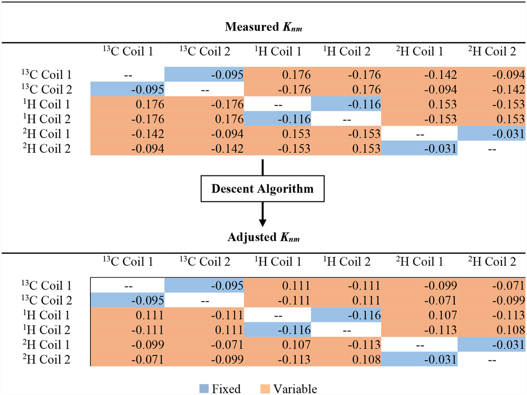
Magnetic coupling coefficients Knm where n ≠ m. Values of Knm for unique parallel and perpendicular orientations were calculated from the measured isolated and coupled-pair resonances. A descent algorithm was used to adjust Knm to minimize the RMSPE between the observed and predicted coupled modes. Couplings between coil pairs highlighted in blue were held fixed. Couplings between 13C and 1H coils required the largest adjustments (from 0.176 to 0.111) with a change of 59%.
|
3. Results and Discussion
3.1. Pre-Trim Results
Using the measured isolated resonances and coupling coefficients, the coupled resonances of the full probe were predicted with 1.26 root-mean-squared-percentage-error (RMSPE) for constructive modes and 5.30 RMSPE for destructive modes (Table 3). While only constructive modes are utilized for NMR detection and irradiation, correctly predicting the destructive modes served as an essential sanity check - ensuring that the coupling model exclusively described the unique set of interactions related to this ensemble of resonators. We suspected that the residual error was primarily due to the evident variability in the mounting positions of the resonators. Some perpendicular resonators had parallel wires that were less than 1 mm apart, so a small mounting error led to a significant difference in coupling. Notably, the difference in coupling coefficients for two pairs of seemingly identical coils mounted in the same location was calculated to be about 30 percent. Therefore, applying probe symmetries to reduce the number of coupling measurements did have an appreciable disadvantage. However, this shortcoming could not be solved by simply measuring all 36 coupling coefficients. The coil spreader forced the six coils into a consistent but unique set of positions when measuring the coupled modes of the full probe. These unique positions were not replicable during experiments where only two coils were measured. Additionally, the 2H detection coils were stacked on top the 13C detection coils during full-up measurements. This position was closely but not perfectly reproduced by mounting a replica 13C coil base in the absence of a 13C detection coil.
Table 3.
Comparison of the measured coupled resonances of the all-HTS NMR probe with the magnetic coupling model’s predictions before trimming. The magnetic coupling model constructed from measured Knm values predicted constructive modes ω1,3,5 and destructive modes ω2,4,6 with 1.26 and 5.30 RMSPE, respectively. Knm was adjusted to account for mounting errors by using a descent algorithm to minimize RMSPE to 0.82 for ω1,3,5 and 0.76 for ω2,4,6.
| Before Trimming | ω1 | ω2 | ω3 | ω4 | ω5 | ω6 |
|---|---|---|---|---|---|---|
| Measured Resonances (MHz) | 89.520 | 93.338 | 137.704 | 147.670 | 542.130 | 651.369 |
| Prediction: Measured Knm (MHz) | 89.988 | 94.436 | 140.636 | 147.750 | 542.754 | 710.705 |
| Prediction: Adjusted Knm (MHz) | 90.797 | 94.563 | 137.697 | 147.866 | 542.496 | 651.379 |
Given that the residual error was small, it was hypothesized that the exact magnetic coupling coefficients could likely be found locally in the 6×6-dimension Knm-space. If this hypothesis was accurate, an additional preliminary measurement of the coupled resonances could be used to overcome mounting errors. A descent algorithm was employed to adjust Knm to minimize the RMSPE between the observed and predicted coupled modes (Table 2). RMSPE was reduced to 0.82 and 0.76 for constructive modes and destructive modes, respectively (Table 3). The largest Knm adjustments were by 59%, which was consistent with the observed variations in mounting position between perpendicular resonators.
3.2. Post-Trim Results
Following a test trim of all coils, the single coil resonances and the adjusted Knm matrix derived above were used to predict the coupled resonances of the full probe (Table 4). It predicted the coupled resonances of the full probe with 0.60 RMSPE and a maximum error of 1.00% for constructive modes. RMSPE for destructive modes was 0.87. As hypothesized, the coupling coefficients were consistent through trimming. However, normal metal tuning loops can only produce a tuning range of about 1% of the coil’s resonance frequency without introducing significant reductions in Q due to transport current and eddy current losses [9]. Thus, tuning procedures for similar all-HTS NMR probes may employ a single trim per coil to get 1–2% below the final resonances. Some coils may require a second trim to fine-tune resonances to within the tuning range of the tuning loops.
Table 4.
Comparison of the measured coupled resonances of the all-HTS NMR probe with the magnetic coupling model’s predictions after trimming. The magnetic coupling model based on the adjusted Knm values predicted constructive modes ω1,3,5 and destructive modes ω2,4,6 with 0.60 and 0.87 RMSPE, respectively.
| After Trimming | ω1 | ω2 | ω3 | ω4 | ω5 | ω6 |
|---|---|---|---|---|---|---|
| Measured Resonances (MHz) | 90.361 | 94.263 | 141.948 | 152.338 | 560.044 | 677.827 |
| Prediction: Adjusted Knm (MHz) | 91.276 | 95.329 | 142.239 | 152.873 | 560.834 | 671.437 |
4. Conclusions
An effective description of the magnetic interactions of a set of proximate HTS resonators was presented. A magnetic coupling model was used to accurately predict the individual coil resonances required for the ensemble of HTS coils to obtain a particular set of coupled modes within an HTS probe. Therefore, it was shown that magnetic coupling comprises the bulk of coil interactions. We expect this model will be more easily applied to probes with immobile coil positions; especially probes with multi-tuned resonators [16]. The implementation of accurate trimming simulations in conjunction with a magnetic coupling model based on the coupling coefficients of intercoupled resonators will result in a significant increase in the efficiency of the built-out process of HTS probes. Future coupling models may consider the effect of capacitive coupling to decrease errors to strictly less than 1%.
Acknowledgments
This work was supported by NIH/NIGMS grants R01GM120151 and P41 GM122698 and by Bruker Biospin. A portion of the work was done at the National High Magnetic Field Laboratory which is supported by the NSF through Cooperative Agreement DMR-1644779 and by the State of Florida. The authors would like to thank Steve Ranner and Jason Kitchen for valuable technical support.
References
- [1].Ramaswamy V, Hooker JW, Withers RS, Nast RE, Brey WW and Edison AS 2013. Development of a C-13-optimized 1.5-mm high temperature superconducting NMR probe J. Magn. Reson 235 58–65 [DOI] [PMC free article] [PubMed] [Google Scholar]
- [2].Kovacs H, Moskau D and Spraul M 2005. Cryogenically cooled probes--a leap in NMR technology Prog. Nucl. Magn. Reson. Spectrosc 46 131–55 [Google Scholar]
- [3].Styles P, Soffe NF and Scott CA 1989. An improved cryogenically cooled probe for high-resolution NMR J. Magn. Reson 1969 84 376–8 [Google Scholar]
- [4].Ramaswamy V, Hooker JW, Withers RS, Nast RE, Edison AS and Brey WW 2007. Microsample Cryogenic Probes: Technology and Applications eMagRes (John Wiley & Sons, Ltd; ) [Google Scholar]
- [5].Yamada T, Saito A, Oikawa S, Koshita K, Takahashi M, Maeda H and Ohshima S 2015. Electromagnetic Evaluation of HTS RF Coils for Nuclear Magnetic Resonance IEEE Trans. Appl. Supercond 25 1–432863691 [Google Scholar]
- [6].Anderson WA, Brey WW, Brooke AL, Cole B, Delin KA, Fuks LF, Hill HDW, Johanson ME, Kotsubo VY, Nast R, Withers RS and Wong WH 1995. High-sensitivity NMR spectroscopy probe using superconductive coils Bull. Magn. Reson 17 98–102 [Google Scholar]
- [7].Oikawa S, Tanaka Y, Yamada T, Kanamaru A, Takahashi M, Saito A and Ohshima S 2014. Evaluation of superconducting pickup coils with high Q for 700 MHz NMR J. Phys. Conf. Ser 507 042028 [Google Scholar]
- [8].Hill HDW 1997. Improved sensitivity of NMR spectroscopy probes by use of high-temperature superconductive detection coils Ieee Trans. Appl. Supercond 7 3750–5 [Google Scholar]
- [9].Ramaswamy V, Edison AS and Brey WW 2017. Inductively-Coupled Frequency Tuning and Impedance Matching in HTS-Based NMR Probes IEEE Trans. Appl. Supercond 27 1–5 [DOI] [PMC free article] [PubMed] [Google Scholar]
- [10].Freytag N. RF resonator system and method for tuning an RF resonator system US7564244B2. 2009.
- [11].Hong J-SG and Lancaster MJ 2004. Microstrip Filters for RF/Microwave Applications (New York, NY: John Wiley & Sons; ) pp 235–272 [Google Scholar]
- [12].Hoult DI, Richards RE and Styles P 1978. A Novel Field-Frequency Lock for a Superconducting Spectrometer J. Magn. Reson 1969 30 351–65 [Google Scholar]
- [13].Brey WW, Anderson WA, Wong WH, Fuks LF, Kotsubo VY and Withers RS 1996. Nuclear magnetic resonance probe coil US5565778A
- [14].Brey WW, Edison AS, Nast RE, Rocca JR, Saha S and Withers RS 2006. Design, construction, and validation of a 1-mm triple-resonance high-temperature-superconducting probe for NMR J. Magn. Reson 179 290–3 [DOI] [PubMed] [Google Scholar]
- [15].Withers RS. Inductively coupled superconducting coil assembly US5585723A. 1996.
- [16].Ramaswamy V, Hooker JW, Withers RS, Nast RE, Edison AS and Brey WW 2016. Development of a 1H-13C Dual-Optimized NMR Probe Based on Double-Tuned High Temperature Superconducting Resonators IEEE Trans. Appl. Supercond 26 1500305 [Google Scholar]