

Abstract
Hemostasis is an innate protective mechanism that plays a central role in maintaining the homeostasis of the vascular system during vascular injury. Studying this essential physiological process is often challenged by the difficulty of modeling and probing the complex dynamics of hemostatic responses in the native context of human blood vessels. To address this major challenge, this paper describes a microengineering approach for in vitro modeling of hemostasis. Our microphysiological model replicates the living endothelium, multilayered microarchitecture, and procoagulant activity of human blood vessels, and is also equipped with a microneedle that can be actuated with spatial precision to simulate penetrating vascular injuries. The system recapitulates key features of the hemostatic response to acute vascular injury as observed in vivo, including i) thrombin-driven accumulation of platelets and fibrin, ii) formation of a platelet- and fibrin-rich hemostatic plug that halts blood loss, and iii) matrix deformation driven by platelet contraction for wound closure. Moreover, the potential use of this model for drug testing applications is demonstrated by evaluating the effects of anticoagulants and antiplatelet agents that are in current clinical use. The vascular injury-on-a-chip may serve as an enabling platform for preclinical investigation of hematological disorders and emerging therapeutic approaches against them.
Keywords: hemostasis, vascular injury-on-a-chip, platelets, fibrin, microphysiological system
Graphical Abstract
Using a biomimetic microengineering approach, the interface between the vascular wall and flowing blood is reconstructed to model hemostasis from injury to wound closure. The vascular injury-on-a-chip system replicates i) multiscale structure, ii) biochemical and biomechanical function, and iii) the dynamic microenvironment that helps to determine the structure of the hemostatic plug as it forms in vivo after injury.
1. Introduction
Hemostasis is a tightly-regulated process that has been studied extensively in humans and animal models. When a closed, high-pressure vascular system is penetrated, bleeding continues until a stable hemostatic thrombus seals the breach and prevents further blood loss (Figure 1a). This process is initiated by the adhesion of platelets to collagen fibrils exposed within the vessel wall. As bleeding continues, escaping blood contacts tissue factor in the matrix surrounding the blood vessel, triggering thrombin generation, further platelet activation, and fibrin accumulation.[1] The growth of this temporary plug is regulated by serpins and protein C which limit thrombin formation and activity,[1a] and by molecules released by endothelial cells, including NO and PGI2, both of which are inhibitors of platelet activation.[2] Concurrently, the growing mass of platelets and fibrin undergoes contractive deformation, helping to contain agonists generated at the site of injury and hindering the exchange of soluble factors. These events shut down coagulation reactions and limit the extent of platelet activation,[3] eventually giving rise to an optimal hemostatic plug that seals the injury in the vessel wall.
Figure 1. A human vascular injury-on-a-chip for in vitro modeling of hemostasis after a penetrating injury.
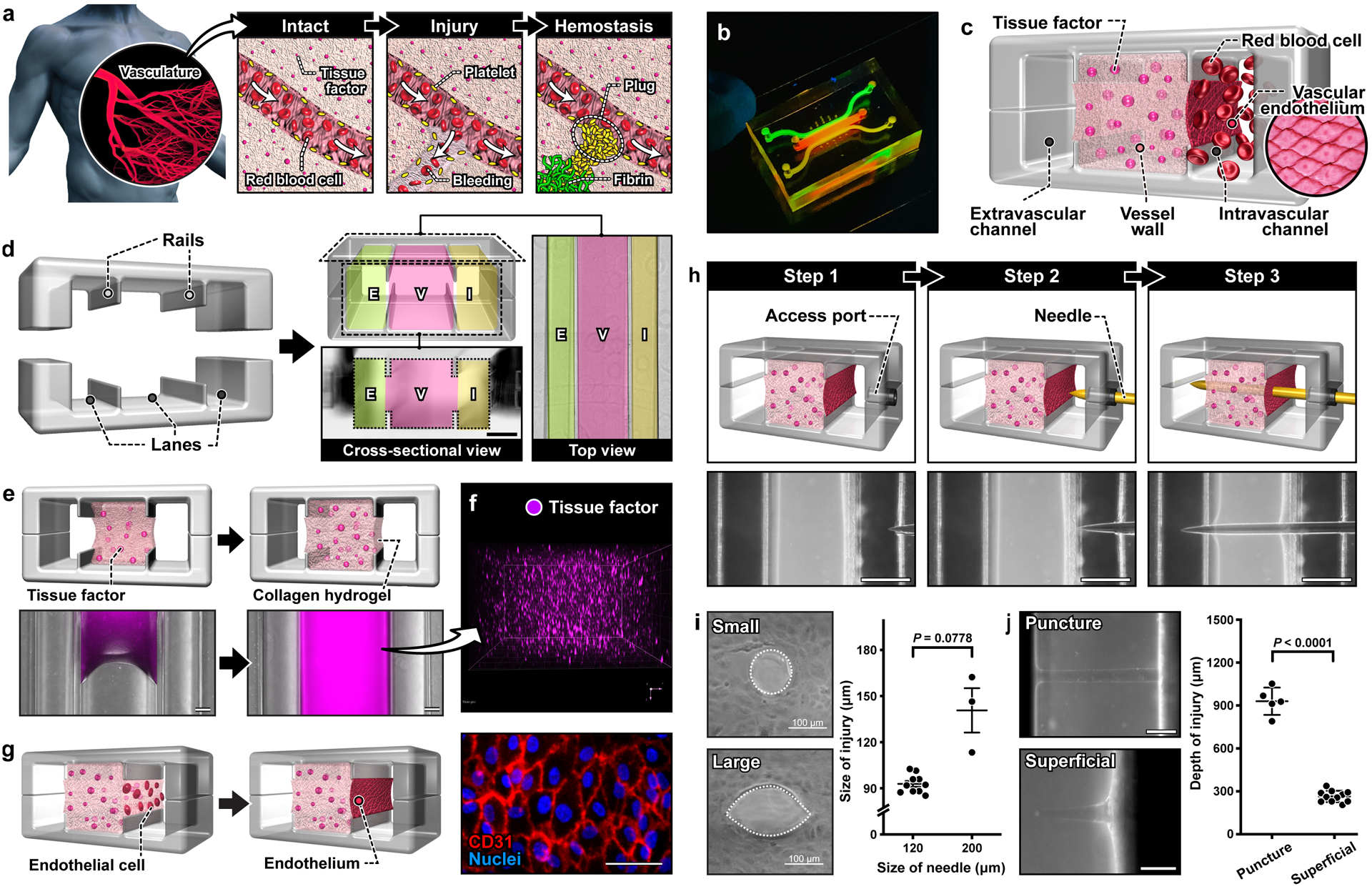
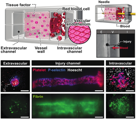
a. When an injury occurs in a blood vessel, a hemostatic plug stops bleeding. b. Image of a blood vessel-on-a-chip microdevice. c. The system is designed to model three distinct tissue compartments at the injury site. d. Microfabricated rails on the top and bottom channel walls divide the assembled microfluidic device into 3 lanes that become the intravascular (I), vessel wall (V), and extravascular (E) compartments. Scale bar, 500 μm. e. Collagen mixed with lipidated tissue factor is loaded and polymerized in the middle lane of the device. f. A 3D projection image shows the homogeneous distribution of tissue factor (stained with annexin V; magenta) in the collagen gel. g. Endothelial cells are seeded directly on top of the exposed collagen gel to form a confluent monolayer. Scale bar, 50 μm. h. Sequential steps to create an injury in the device. The micrographs show the top view of the device as an acupuncture needle is inserted through the engineered vessel wall. Scale bars, 500 μm. i. Representative images and quantification of puncture injuries that result from the insertion of 120 μm (small) and 200 μm (large) needles. j. Representative images of injuries with different penetration depths. Scale bars, 200 μm (puncture) and 100 μm (superficial). Graphs show mean ± SEM. An unpaired t-test with Welch’s correction was used for statistical analysis in i and j.
Research advances in hematology have led to the development of multiple ways to investigate hemostasis. Most of our fundamental knowledge about hemostasis comes from animal studies.[4] For example, the tail clip assay is the most common method to study hemostasis in mouse models.[5] In the last decades, this technique combined with real-time intravital microscopy have greatly advanced our understanding of how platelets and coagulation factors interact in a very dynamic environment at the injury site.[6] While animal models provide a more integrative approach, their ability to faithfully recreate hemostatic events in humans is limited by interspecies differences in the size and number of platelets, their sensitivity to biochemical mediators of hemostasis, and the distribution of coagulation factors.[7]
Assessment of hemostatic function in humans is achieved primarily by gathering the clinical history of the patient and the results from laboratory tests. The only in vivo hemostasis assay conducted in humans is to make a slice of predefined length and depth in the skin and measure the time to bleeding cessation, which is known as the template bleeding time. This method has fallen from favor in the clinical setting due to the lack of reproducibility, sensitivity, and specificity.[5, 8]
In vitro models using human cells have been developed as an alternative to in vivo studies.[9] However, most in vitro models often suffer from limited capacity to reproduce the dynamic microenvironment in which the hemostatic response normally occurs. In addition, these systems can only measure limited aspects of the hemostatic response such as platelet aggregation or thrombin generation, typically failing to recapitulate the whole process that is initiated with vascular injury and completed with wound closure.[9]
Motivated by these limitations and the need for better tools to predict the impact of new drugs on hemostasis, new approaches have been developed that exploit engineering techniques and design principles. One promising strategy has been to use microfluidics and microfabrication technologies to study the interaction of blood with procoagulant environments under flow, thereby modeling important aspects of hemostasis such as platelet activation and fibrin accumulation.[10] However, major advances have yet to be made in emulating the most defining features of hemostasis. Specifically, there is an unmet need for model systems that can faithfully recapitulate the biological complexity of the vasculature, including the living vascular endothelium and extravascular tissue factor arranged in a physiologically relevant manner. It also remains a challenge to realistically mimic the structural disruption of the multilayered vascular tissue during injury and its biomechanical alterations over the course of hemostatic responses. Perhaps most importantly, it is currently not possible to capture in detail key processes of the hemostatic response from vascular injury to formation of a temporary hemostatic plug comprised of platelets and fibrin in a single system. Without these capabilities, the majority of existing models are arguably better suited to studies of thrombosis than hemostasis.
Here we describe our efforts to address these challenges and advance the state-of-the-art for in vitro modeling of hemostasis in humans. Our work introduces a novel microfabricated platform that enables microengineering of biologically active, deformable three-dimensional (3D) extravascular tissue and its integration with the living endothelium of the human vasculature in a precisely controlled physiological environment with the flow of human whole blood. This paper also presents a new method for modeling vascular injury in which a mechanically actuatable microneedle is used to pierce the wall of a microengineered blood vessel, creating a transmural pressure drop that drives the escape of blood. Using this system, we demonstrate the feasibility of simulating the hemostatic response in its entirety. Through microfluorimetric imaging and analysis of on-chip hemostasis, we provide quantitative data on the dynamics of hemostatic plug formation and injury closure, and show their similarities to in vivo situations. Moreover, we demonstrate the proof-of-principle of using our model for applications in preclinical drug screening by showing its ability to reproduce the known effects of anticoagulants and antiplatelet agents on the hemostatic response. To the best of our knowledge, this human blood vessel-on-a-chip is the most complete model of human hemostasis currently available and may provide a basis for developing advanced in vitro technologies with the potential for broad impact on hematology research.
2. Results
2.1. Microengineering of human blood vessel-on-a-chip
As a critical first step towards modeling hemostasis in vitro, we created a microphysiological model of a human blood vessel in an optically transparent microfluidic device (Figure 1b, Figure S1). The unique design of this system characterized by three interconnected parallel microchambers provided a means to emulate physiological compartmentalization of vascular tissue. Specifically, the middle chamber was designed to house a 3D collagen hydrogel containing homogenously distributed tissue factor to model the deformable, procoagulant wall of a blood vessel(Vessel wall in Figure 1c). The microchannel along the right side of this microengineered vessel wall was used to represent the intravascular compartment in which the human vascular endothelium was generated on the exposed hydrogel surface and perfused with whole blood at a venous shear rate to recapitulate the hemodynamic environment of the native vascular system (Intravascular channel in Figure 1c). The left microchannel served as an extravascular compartment into which blood can escape when a hole is punched through the vessel wall (Extravascular channel in Figure 1c).
To construct this model, we generated a pair of identical PDMS microchannels, each of which consisted of three parallel lanes separated by two thin microfabricated rails running along the length of the channel (Figure 1d). Alignment and permanent bonding of the two channel layers produced a sealed microdevice containing a microchamber with cross-sectional dimensions of 1 mm (width) × 1 mm (height) flanked by two microchannels that measured 500 μm (width) × 1 mm (height) (Figure 1d). Importantly, the middle chamber was open to the side channels through the gap between the upper and lower rails but the three compartments were equipped with their dedicated access ports for independent fluidic control.
Model construction in this device began with the injection of a collagen hydrogel precursor solution mixed with lipidated tissue factor into the middle chamber. During this step, the injected solution was pinned at the microfabricated rails by surface tension,[11] which effectively prevented the spillage of liquid into the side channels (Figure 1e). Thanks to the pinning effect, the solution remained confined stably between the rails while advancing along the entire length of the chamber (Figure 1e). The net result was that after gelation, the middle chamber was entirely filled with a tissue factor-laden collagen hydrogel firmly anchored to the PDMS surfaces functionalized for strong interfacial adhesion with long-term stability (Figure 1e and 1f).[12] Culture of primary human umbilical vein endothelial cells (HUVECs) on the exposed collagen surface led to the formation of an endothelial barrier with structural integrity (Figure 1g).
2.2. Simulation of penetrating vascular injury in the blood vessel-on-a-chip
Our compartmentalized microphysiological platform was then further engineered for in vitro modelling of bleeding due to penetrating vascular injury. To this end, we devised a technique to interface the microengineered vascular tissue inside our device directly with a microneedle that can be controlled with high spatial precision from the macroscopic external environment (Figure 1h, Video S1). In this method, a cylindrical access port was created sideways between the two halves of the device to permit direct entry into our vascular model (Step 1 in Figure 1h). To create the injury, a flexible needle was inserted through the rigid access port and guided into the intravascular channel (Step 2 in Figure 1h), piercing the endothelial barrier and the collagen hydrogel construct, and reaching the extravascular channel on the other side (Step 3 in Figure 1h). Withdrawing the needle generated an open puncture wound across the vessel wall (Figure 1i).
Our results also demonstrated the feasibility of controlling the physical characteristics of vascular injury generated by this technique. For example, the size of the endothelial injury was readily changed by changing the diameter of the needle (Figure 1i). It was noted, however, that the collagen matrix comprising the vessel wall relaxed when the needle was withdrawn, resulting in a 20–30% reduction in the size of the injury (Figure 1i). It was also possible to control the injury depth, which was conducive to modeling injuries of different severity. This capability was demonstrated by creating fully-penetrant injuries spanning the entire vascular construct and superficial injuries that penetrated only 25% of the full thickness of the vessel wall (Figure 1j). In either case, needle penetration was accomplished with precision and reproducibility as illustrated by less than 15% variation in the depth of injury (Figure 1j).
2.3. Formation of hemostatic plugs following injury
To assess hemostatic plug formation, the intravascular channel was perfused with human whole blood recalcified in the presence of corn trypsin inhibitor at a venous shear rate of 100 s−1, while a buffer solution was pulled through the extravascular channel at 0.5 s−1. When the vessel wall was punctured with the needle, the difference in the rates of flow in the intravascular and extravascular channels produced a pressure drop across the vascular construct, promoting the blood in the intravascular compartment to escape into the extravascular channel (Figure 2a, Figure S2, Video S2).
Figure 2. Formation of platelet and fibrin-rich hemostatic plugs after a puncture injury.
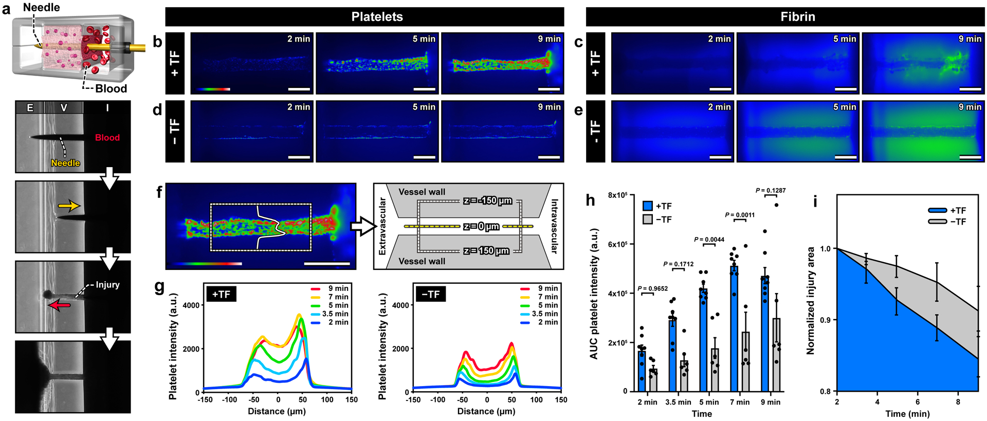
. a. In the microdevice, bleeding is modeled as the leakage of blood through the injury due to the pressure difference between the intravascular (I) and extravascular (E) channels. Representative images of platelet deposition (b,d) and fibrin accumulation (c,e) in the presence (top row) and absence (bottom row) of tissue factor (TF). Scale bars, 200 μm. The color scale in b and d indicates the number of platelets. Green in c and e shows fluorescence emitted by anti-fibrin antibody. In the presence of TF (c), fibrin deposits are detected as aggregates with intense green fluorescence in the injury channel at 9 min. The diffuse green haze seen in the matrix, particularly in the absence of TF, is due to the absorption of the fluorescently-tagged anti-fibrin antibody into the hydrogel vessel wall. f. A region of interest in the vessel wall (shown with dotted lines) for microfluorimetric analysis of platelet deposition across the width of the injury. g. Line scan of fluorescence intensity averaged over the length of the injury channel. h. Plot of the area under the curves in g over time. i. Quantification of the change in the area of the 2D view of the injury shows greater matrix contraction over time in the presence of TF. Graphs show mean ± standard error (3 donors; +TF: 8 devices, -TF: 6 devices). Two-way ANOVA and Tukey’s multiple comparison tests were used for statistical analysis in c and d.
The optical transparency of our device made it possible to directly observe this dynamic process of bleeding and measure the kinetics of platelet accumulation. For real-time imaging, fluorescently-labeled antibodies to CD61, P-selectin, and fibrin were added to the blood perfused through the microfluidic device. Prior to injury, no platelet adhesion was observed in the intravascular channel, illustrating the role of the intact endothelial barrier in preventing thrombotic events. Within a few minutes of injury, however, platelets adhered to the surface of the exposed collagen matrix and began to form small aggregates over time (Figure 2b,Video S3). Most of these deposits were initially observed at the ends of the puncture but with time platelet accumulation became pronounced and extended throughout the injury as the aggregates grew larger. Although the leakage of unbound fibrin antibody into the collagen matrix generated background signal in the vessel wall, fibrin deposition was clearly visible as filamentous structures within the injury channel (Figure 2c, Video S3). This simultaneous accumulation of platelet and fibrin produced hemostatic plugs that halted blood loss within 10 minutes of injury.
After confirming the ability of our model to generate hemostatic plugs, the first question that we investigated was whether the lipidated tissue factor embedded in the collagen matrix influenced the hemostatic response. Interestingly, when the experiments were conducted in the absence of tissue factor, we observed drastically reduced platelet and fibrin accumulation at the injury site (Figure 2d and 2e). To examine this difference quantitatively, we analyzed the spatiotemporal distribution of platelet deposition by selecting a region of interest within the injured vessel wall (Figure 2f) and measuring the intensity profile of platelets over time. Regardless of whether tissue factor was present, the initial deposits occurred at the edges of the injury (Figure 2g). However, when the collagen hydrogel contained tissue factor, this localized event propagated towards the center of the injury over a short period of time, leading to a rapid, substantial increase in fluorescence intensity across the entire width of the puncture (Figure 2g; left). This spatiotemporal pattern of platelet deposition was significantly altered by leaving out tissue factor. In this case, the intensity increase was markedly reduced, and changes in fluorescence occurred in a more localized manner along the edges of the injury (Figure 2g; right).
Quantification of the area under the curve of the intensity profiles also showed that platelet accumulation occurred at a faster rate in the presence of tissue factor, reaching a peak within about 7 minutes of bleeding (Figure 2h). After that time, the fluorescence signal did not change much, indicating no further platelet deposition. We also noted rapid contraction of the tissue factor-containing collagen matrix and a resultant decrease in the diameter of injury over the course of bleeding (Video S2), which was evidenced by more than 15% reduction in the area of injury by the time of wound closure (Figure 2i). In the absence of tissue factor, matrix deformation occurred to a much lesser extent (Figure 2i).
2.4. Platelet activation and fibrin formation
To further characterize the structure of hemostatic plugs in our microfluidic system, we used confocal microscopy to examine the spatial distribution of activated platelets and fibrin after bleeding through the injury channel stopped. Consistent with the findings of real-time imaging analysis described in Figure 2, maximum intensity projection images showed considerably increased platelet accumulation, P-selectin expression, and fibrin formation due to the presence of tissue factor in the microengineered vascular construct (Figure 3). Our analysis of hemostatic plugs in this procoagulant model revealed the following characteristics. First, the puncture injury was completely clogged with platelets, which was best visualized by the cross-sectional image of the injury opening on the extravascular side – the vast majority of platelets were found in the hole (Figure 3a). Platelets were more widely distributed around the intravascular end of the injury to form a plug-like structure that sealed the breach (Figure 3a). Second, most of P-selectin-positive platelets were detected at the edges of the injury channel (Figure 3a). Importantly, this pattern of platelet activation bears significant similarities to what has been previously seen in vivo[13]. The deposition of fibrin occurred in a similarly localized fashion and was observed mainly along the exposed surface of the injury within the vessel wall (Figure 3a). Finally, our data also revealed strikingly different microscopic features of hemostatic responses in the absence of tissue factor. The difference was immediately apparent from the failure of wound closure. A number of adherent platelets were observed at both the intravascular and extravascular ends of the injury, but they accumulated only in the vicinity of the puncture without filling the openings (Figure 3b). Similarly, platelet deposition within the vessel wall was confined to the surface of the injury channel (Figure 3b). Another feature distinct from the tissue factor-containing model was the significantly decreased extent of platelet activation (Figure 3c) and fibrin accumulation, which was almost negligible (Figure 3d).
Figure 3. Characterization of platelet activation and fibrin formation.
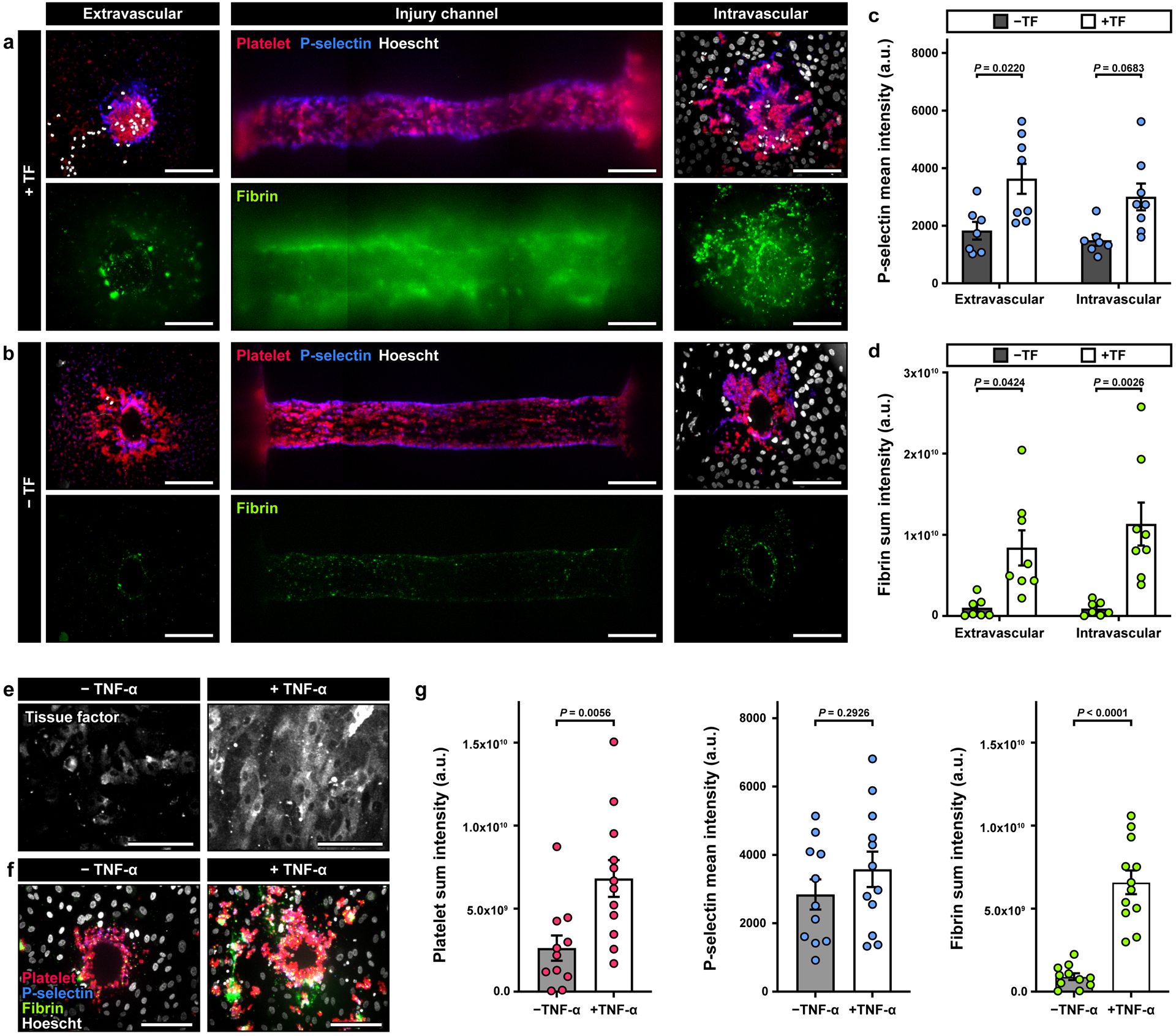
a, b. Maximum projection confocal images of the injury opening on the extravascular (left) and intravascular (right) sides. The middle column shows the top-down view of the injury in the vessel wall. Red, blue, green, and white show immunostaining of platelets, P-selectin+ platelets, fibrin, and cell nuclei. Quantification of the mean fluorescence intensity (MFI) of P-selectin (c) and the sum intensity of fibrin (d) from a 40 μm-thick z-stack. The results indicate an increase in intravascular platelet activation and fibrin accumulation in the presence of TF, and an increase in fibrin at the extravascular end of the channel (3 donors; +TF: 8 devices, -TF: 6 devices). e-g. Devices were perfused overnight with buffer ± TNF-α (1 ng/ml) prior to the start of the experiment. Tissue factor was not embedded in the collagen gel. e. Confocal images show increased TF expression in endothelial cells after TNF-α treatment. f. Confocal images obtained from the intravascular side of the injury channel after blood perfusion illustrate an increase in platelet and fibrin accumulation in TNF-α-treated devices. g. Quantification of platelet and fibrin sum intensity, and P-selectin MFI, (4 donors; +TNFα: 11 devices, - TNFα: 10 devices). Data are shown as mean ± SEM. Two-way ANOVA and Tukey’s multiple comparison tests were used for the statistical analysis in c and d. Welch’s t-test was used for statistical analysis in g.
Taken together, these results showed the critical role of tissue factor in hemostasis of our vascular injury model. In this study, however, we also asked whether the location of tissue factor influences the formation of competent hemostatic plugs in our system. To answer this question, we created a condition in which tissue factor was localized on the endothelial lining of the intravascular channel, rather than being embedded in the collagen matrix, by treating the endothelium with tumor necrosis factor (TNF)-α, which is a known inducer of endothelial tissue factor expression. As expected, overnight treatment with 1 ng/ml of TNF-α resulted in robust and widespread expression of tissue factor in the endothelial cells (Figure 3e). Bleeding caused by the puncture injury in this model triggered the hemostatic response and led to aggregation of platelets at the injury site (Figure 3f). In comparison to the control group that did not receive TNF-α, we observed substantially increased deposition and activation of platelets over a larger surface area, which was accompanied by more pronounced fibrin production and accumulation (Figure 3f). The increased thrombotic activities may be explained by the high levels of tissue factor present on the TNF-α-treated endothelial surface. The enhanced hemostatic response in this system, however, still failed to form plugs necessary to seal the opening of the injury (Figure 3f), providing further evidence that tissue factor situated in the subendothelial compartment of the blood vessel wall is essential for proper hemostasis.
2.5. Direct visualization of hemostatic plugs for in vitro-in vivo comparison
Among the advanced techniques for the study of hemostasis in animal models is to surgically remove injured blood vessels for high-resolution visualization and analysis of thrombus formation.[13] Inspired by this approach, we explored the feasibility of gaining access to the microengineered vascular construct after injury in order to directly observe and probe the microarchitecture of hemostatic plugs. To this end, we developed a method analogous to microsurgical techniques that rely on a microscopically guided and manipulated scalpel blade to excise the intravascular and extravascular compartments and expose the injured vessel wall (Figure 4a). By making the entire tissue construct readily accessible from the external environment, this technique permits direct visualization of the intravascular and extravascular surfaces around the injury site using scanning electron microscopy (SEM).
Figure 4. In vitro-in vivo comparison of hemostatic plugs using SEM.
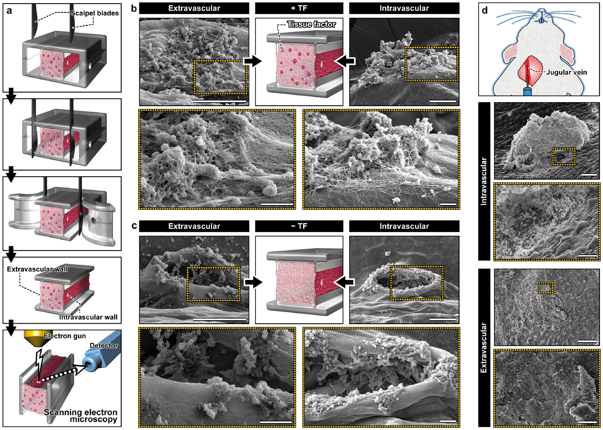
a. Microblades are used to precisely excise the device and expose the intravascular and extravascular sides of the hemostatic plugs formed in the vascular injury-on-a-chip for morphological examination using SEM. b. In the TF-containing device, hemostatic plugs composed of platelets (spherical aggregates) and fibrin (fibrous meshwork) fill the holes in the intravascular and extravascular sides of the injury. Scale bars, 60 μm (top; lower magnification) and 10 μm (bottom: higher magnification). c. In the absence of TF, platelets adhere to the exposed collagen, but fail to fill the hole created by the injury. Scale bars, 60 μm (top; lower magnification) and 10 μm (bottom: higher magnification). d. Scanning electron micrographs obtained from a murine model of jugular vein injury show a large hemostatic plug and a dense network of platelets and fibrin at the intravascular and extravascular openings of the injury, respectively. Scale cars, 100 μm (intravascular; lower magnification) and 50 μm (intravascular; higher magnification), 300 μm (extravascular; lower magnification) and 30 μm (extravascular; higher magnification).
The SEM micrographs clearly showed a large number of platelets localized to the injury site, many of which formed 3D aggregates (Figure 4b). These platelet deposits were entangled in a highly dense fibrous network of fibrin formed on the surface of the endothelium (Figure 4b). Importantly, these composite structures filled and completely covered the opening of the puncture injury on both the extravascular and intravascular sides (Figure 4b), corroborating the findings of confocal microscopy (Figure 3). When tissue factor was not present in the wall, however, we did not observe any plugs of similar size and architecture (Figure 4c). Although small aggregates were seen along the edges of the injury opening, the hole created by piercing injury was not occupied by platelets or other components of blood and remained unobstructed (Figure 4c).
To compare the hemostatic plugs in the vascular injury-on-a-chip with those formed in vivo, a mouse jugular vein was punctured with a 30-gauge needle, fixed and excised 5 minutes postinjury, and prepared for SEM. Consistent with the hemostatic response in our device, the micrographs showed a 3D aggregate of platelets on the intravascular side that filled the opening of the injury (Figure 4d). In comparison to our model, the hemostatic plug was bigger, and no fibrin was visible in and around the aggregate (Figure 4d). Closure of the injury also occurred on the extravascular side but the opening was covered with a dense carpet of platelets and fibrin (Figure 4d) similar to what was observed in the vascular injury-on-a-chip.
2.6. Human vascular injury-on-a-chip as a drug screening platform
Anticoagulants and antiplatelet agents are commonly used for treating or preventing thrombotic events in the arterial and venous circulations.[14] However, all of the anticoagulants and antiplatelet agents currently on the market also increase the risk of bleeding, especially when used in combination. The vascular injury-on-a-chip model provides a potential tool for evaluating these adverse effects, offering a complementary approach to animal studies.
To explore this potential, we conducted a proof-of-concept study using hirudin and eptifibatide as model compounds representing anticoagulant and antiplatelet drugs, respectively. The goal of this study was to measure and compare the extent of injury-induced platelet and fibrin deposition when our devices were perfused with drug-containing whole blood. When hirudin was administered at a clinically relevant concentration (4 μg/ml), our analysis showed no statistically significant changes in platelet accumulation and activation as compared to control without the drug (Figure 5a and 5b, Video S4). Hirudin did, however, drastically reduce fibrin accumulation, illustrating its efficacy as a thrombin inhibitor (Figure 5c, Video S4). Under this condition, the intravascular end of the injury channel remained open, but platelet aggregates blocked the extravascular opening (Figure 5d). For quantitative analysis, we devised an injury closure score ranging between 0 and 2, which corresponds to fully open and fully closed, respectively. The hirudin-treated devices yielded an average score of 0.475 while the untreated control group scored 1.138. (Figure 5e), indicating the adverse effects of hirudin on the formation of competent hemostatic plugs.
Figure 5. Drug testing in the vascular injury-on-a-chip.
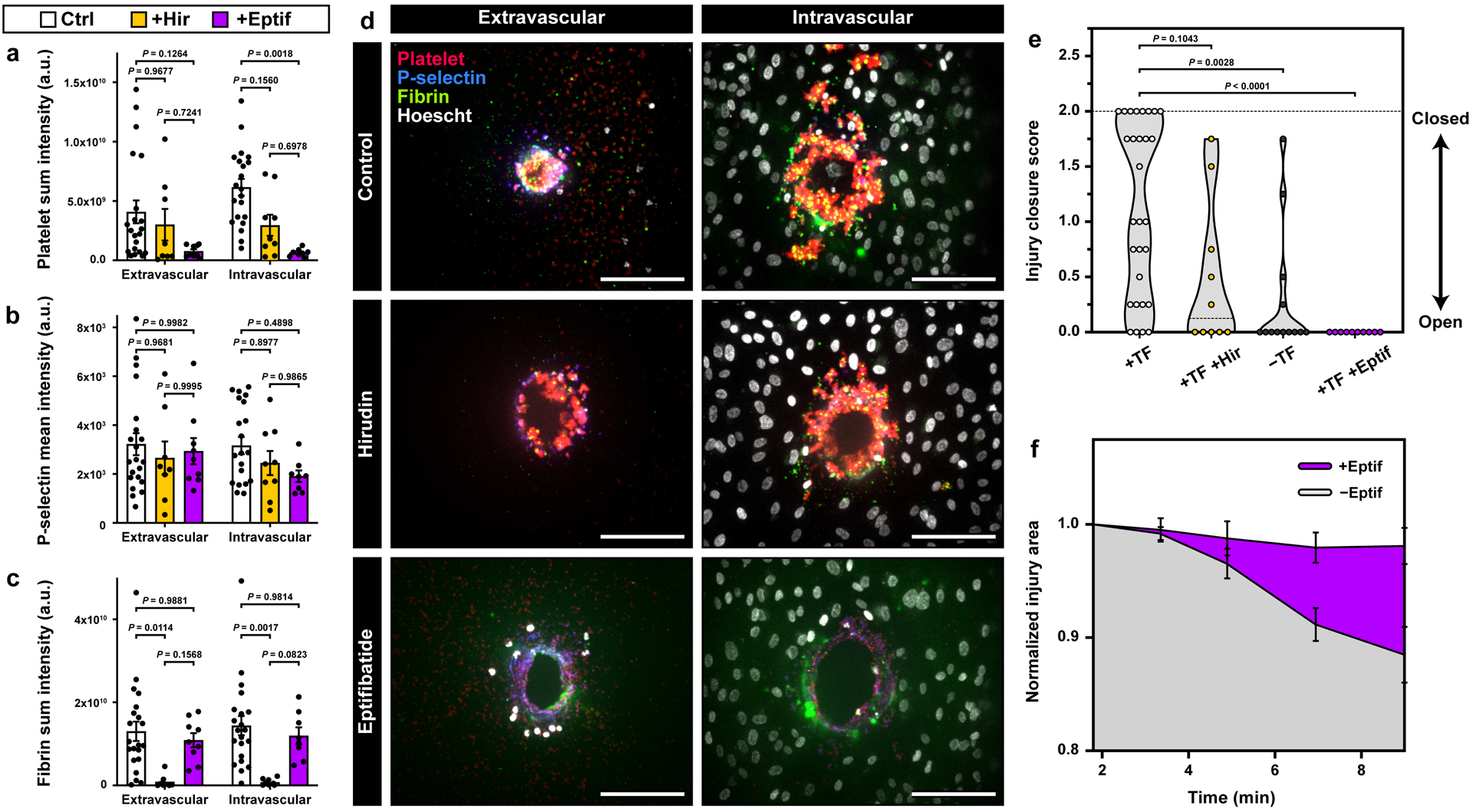
a-c. Quantification of platelet deposition (a), platelet activation (b), and fibrin accumulation (c) in the hirudin- and Eptifibatide-treated devices (Control: 6 donors, 21 devices; Hirudin: 4 donors, 9 devices; Eptifibatide: 4 donors, 9 devices). d. Representative maximum projection confocal images of the extravascular (left) and intravascular (right) injury openings with no treatment (top), hirudin (middle), and eptifibatide (bottom). e. Violin plot of the injury channel closure scores obtained at the final time point (+TF: 8 donors, 29 devices; +Hir: 4 donors, 10 devices; -TF: 5 donors, 13 devices; +Eptif: 4 donors, 10 devices). f. Quantification of changes in normalized injury area over time as assessment of platelet-driven matrix deformation (4 donors, +Eptif: 10 devices, -Eptif: 12 devices). Graphs in a-c and f show mean ± SEM. Two-way ANOVA and Tukey’s multiple comparison tests were used for statistical analysis in a-c and f. Kruskal-Wallis and Dunn’s multiple comparison tests were used in e. The results show that in our model, eptifibatide causes reduction in platelet accumulation, platelet activation, matrix deformation, and injury channel closure. Hirudin inhibits fibrin accumulation and injury closure.
In contrast to hirudin, introduction of the antiplatelet agent, eptifibatide (100 μM), did not change the extent of fibrin accumulation relative to control (Figure 5c, Video S4), but did markedly reduce platelet accumulation (Figure 5a and 5b, Video S4). In this case, the injury channel remained open as illustrated by its unobstructed ends (Figure 5d) and an injury score of 0 (Figure 5e). Failure of hemostasis in the eptifibatide-treated devices was further evidenced by negligible contraction of the vessel wall (Figure 5f).
3. Discussion
This paper describes a novel bioengineering approach to emulating the human hemostatic response to injury without the use of animal models. By combining microengineering design principles with primary human cell culture, our goal was to demonstrate the feasibility of reverse engineering the complex, dynamic process of hemostasis in human blood vessels. The microphysiological system described here has proved to be capable of mimicking the entire process of the hemostatic response from injury to bleeding to wound closure, all of which can be visualized in real time. We also show the potential of our vascular injury-on-a-chip for applications in drug testing.
From a broader perspective, our work also reflects ongoing efforts to harness the power of microengineering technologies for hematology research. A number of recent studies based on this approach have developed microfabricated systems for in vitro modeling of thrombosis and hemostasis.[15] For example, a recent paper described a microfluidic model consisting of two flow chambers connected by a small microchannel to mimic a breached vessel wall.[15c] By flowing whole blood through a fixed connecting channel coated with collagen and tissue factor, this study demonstrated coagulation and the resultant blockage of the channel. In another recent work, a microfluidic device was created that used an integrated pneumatic valve to generate a small opening in an endothelialized microchannel to model bleeding and hemostatic events following endothelial injury.[15b] While these systems offer capabilities not attainable in traditional cell culture models or in microfluidic devices comprised of a single channel coated with collagen and/or tissue factor, our vascular injury-on-a-chip provides unique advantages that represent a significant advance in our ability to model hemostasis in vitro. Among these are the following:
First, our system enables the integration of the key elements of the vascular system that are essential for hemostasis in a more seamless and comprehensive manner than previously demonstrated. Our device permits the flow of human whole blood at physiological rates in a microchannel lined with primary human vascular endothelial cells that are supported by a deformable hydrogel containing collagen and tissue factor to mimic two key components of the vessel wall. In this configuration, the living endothelium serves as a barrier between the perfused blood and the procoagulant subendothelial compartment, recreating elements of the structural organization and hemodynamic environment of native vessels.
Second, our model is equipped with a controllable microneedle that can simulate an acute vascular injury, making it possible to replicate and potentially replace the kinds of puncture injuries used in animal models of hemostasis.[6b, 13, 16] The needle injury in this case creates a controlled breach in the vessel wall of physiologically-relevant size, across which a pressure drop helps to drive blood from the intravascular channel to the extravascular channel. Along the way, the escaping blood comes into contact with collagen and tissue factor, triggering platelet adhesion, platelet activation, the localized generation of thrombin, and the formation of a hemostatic plug. At the same time, the deformable vessel wall retracts, a process that is driven by activated platelets and contributes to the closure of injury. These events mirror the hemostatic response in vivo, achieving a level of realism greater than has been achieved previously.
Finally, our work also provides a proof-of-principle for using the vascular injury-on-a-chip as a preclinical model to assess the impact of drugs on platelet accumulation and fibrin deposition. Thus, we observed that hirudin inhibited fibrin formation (as would be expected), while exerting negligible effects on platelet accumulation. Eptifibatide, in contrast, reduced platelet accumulation with minimal changes in fibrin deposition (Figure 5). It also inhibited injury channel closure to a greater extent than hirudin. Taken together, these findings show that the hemostatic response in our system depends on both platelet accumulation and fibrin deposition.
For a balanced discussion of our study, however, it should be noted that significant differences still exist between the responses observed in our engineered system and the reality of hemostasis in native blood vessels. For example, in a recent study we have shown that complete closure of needle injuries of a similar size (125 μm) in the jugular veins of mice occurs in less than 1 minute,[13] which is faster than the 7–10 minutes needed in our model. We also noticed that even when embedded tissue factor was present, some injuries in our device failed to achieve full closure within the observation period (up to 10 minutes). Although there was some variability in the time required, all of the injuries in the mice stopped bleeding. These differences could be due to the absence of additional procoagulant factors that are present in vivo, but could also reflect differences in the distribution of collagen and tissue factor in the engineered model compared to arteries and veins of similar size in vivo. Unlike the homogeneous acellular matrix of collagen that represents the vessel wall in our system, the wall of a real blood vessel incorporates multiple types of specialized cells (e.g., fibroblasts, vascular smooth muscle cells, and pericytes), contains more than one type of collagen, and restricts tissue factor to the outer reaches of the vessel wall rather than throughout.
Another important difference noted in this work was the appearance of fibrin at the intravascular end of the injury channel (Figure 3a), which we do not see after injuries in the mouse jugular vein (Figure 4d). In the jugular vein injuries, fibrin is found primarily at the extravascular surface of the wound; little or none is at the intravascular surface. This difference may also be attributable to the greater proximity of tissue factor to the intravascular space in our microfluidic device. We speculate that as the injury closes, flow through the injury channel gradually decreases, allowing thrombin generated within the injury channel to leak into the intravascular channel. This is less likely to occur in the native vasculature because of differences in the spatial localization of tissue factor.[16–17] The appearance of the extravascular surface of the jugular vein wound suggests that a lot more thrombin is being generated based on the amount of fibrin that is visible and the highly activated morphology of the platelets, compared to what occurs in our model (Figure 4).
These differences provide opportunities to improve the complexity and physiological relevance of our microengineered system. For instance, our device can be modified to increase the number of individually accessible parallel chambers/lanes, each of which could contain different materials to more faithfully mimic the multilayered microarchitecture of the blood vessel wall. The same approach may also provide a means to achieve an in vivo-like spatial distribution of perivascular cells. Although the present study focused on modeling the venous system, it is possible to recreate arterial conditions by changing hemodynamic parameters such as the flow rate.
In the current study, we only tested the system using venous shear rate and empirically determined the flow rate in the extravascular channel in such a way that leakage of blood occurred preferentially through the injury channel, not through the intact collagen hydrogel scaffold. To enhance the physiological realism of our model, it is necessary to further investigate the dynamics of blood flow and its implications on the transport of key hemostatic factors in our device relative to the hemodynamics of the native system. These types of studies would be greatly facilitated by the integration of microfluidic cell culture with sensing components that can monitor fluid velocity and pressure in real time. Similarly, further instrumentation of our model to automate the process of generating piercing injuries may help increase experimental precision and reproducibility and provide a means to simulate different injury dynamics.
Work also remains to be done to expand the scope of analysis in the vascular injury-on-a-chip. A novel feature of our model highlighted in this study is the deformation of the vessel wall due to contractile forces generated by activated platelets. The ability to capture this aspect of hemostasis opens up the possibility of probing biophysical characteristics of the hemostatic response that have not been easy to study in vivo, including clot consolidation, reinforcement, and stability. On the basis of recent evidence showing differences in the contribution of platelet P2Y12 ADP receptor signaling depending on injury size,[13] our system may also provide a useful platform to investigate whether and how the severity of injury influences the activity of different molecular pathways involved in hemostasis.
Lastly, the design of our system, especially the 3D collagen hydrogel compartment, provides the flexibility to incorporate additional cellular and acellular components to mimic the vessel wall more precisely and extend our system for in vitro modeling of pathophysiological situations. For example, it is possible to incorporate pericytes and other cellular components (e.g., fibroblasts) of the subendothelial tissue to account for their contributions to hemostatic and thrombotic events demonstrated by previous studies.[18] Modifying the amount of TF or incorporating other prothrombotic molecules (e.g., oxidated LDL) into the matrix in conjunction with cellular components known to play a role in plaque formation can serve as a model to study thrombus formation after plaque rupture. Leveraging the tunability of the hydrogel, it may also be possible to modify the mechanical properties of the scaffold in order to model hemostasis and thrombosis in blood vessels with altered tissue mechanics due to vascular diseases (e.g., atherosclerosis). Altogether, these possible adaptations and improvements may extend the application of our microphysiological system and potentially make important contributions to developing novel platforms for more reliable preclinical drug screening as demonstrated by recent studies.[19]
4. Conclusion
This paper presents an advanced in vitro technology realized by a biomimetic microengineering approach that represents an important first step towards fulfilling the significant unmet need for physiologically relevant and predictive models of hemostasis in the human vascular system. The main findings suggest that the vascular injury-on-a-chip model provides a potentially powerful tool for emulating and probing the inner workings of the hemostatic response. The microengineered platform and the set of analytical techniques demonstrated here are readily applicable to the study of thrombosis and bleeding scenarios. We believe that our technology has the potential for broad impact and may facilitate development of new preclinical approaches to assess existing and emerging therapies for restoring the hemostatic balance.
5. Experimental Section
Materials:
The sylgard ® 184 silicone elastomer kit was purchased from Dow Corning. Collagen I, high concentration, rat tail was purchased from Corning; Dade® Innovin ® reagent, from Siemens; and corn trypsin inhibitor (CTI), from Haematologic Technologies. Anti-CD61 (VI-PL2) antibody was purchased from BD Pharmingen, anti-P-selectin (AK4) antibody was purchased from Biolegend, and anti-fibrin antibody that does not bind to fibrinogen was a gift from Rodney Camire, PhD (Children’s Hospital of Philadelphia). The antibodies were fluorescently labeled using the Alexa Fluor™ antibody labeling kits (488, 568, and 647) from Life Technologies, according to the manufacturer’s instructions. Eptifibatide acetate and dopamine hydrochloride were purchased from Sigma-Aldrich. Hirudin was obtained from Profacgen (HY0073HL). Annexin V was a gift from Sriram Krishnaswamy, PhD (Children’s Hospital of Philadelphia) and was labeled as described.[20] TNFα was purchased from Peprotech (300–01A). Human coagulation factor III/tissue factor antibody was purchased from R&D Systems (AF2339), Alexa Fluor 647 mouse anti-human CD31 (clone WM59) was purchased from BD Pharmingen (561654), and ICAM-1 was purchased from Biolegend (353102).
Microfluidic device fabrication:
SU-8 masters containing the microfluidic channel features were prepared by conventional photolithographic techniques and used to fabricate our blood vessel-on-a-chip devices. Poly(dimethylsiloxane) (PDMS) base (Sylgard 184, Dow Corning) was mixed with a curing agent at a weight ratio of 10:1, degassed to remove air bubbles, and poured onto the masters. After baking at 65 °C for 3 hours, the cured polymer was peeled from the masters to generate two PDMS layers embossed with microchannel features. In one of the layers, inlet and outlet ports were made using a biopsy punch to gain fluidic access to the microchannels. For device assembly, the micropatterned PDMS slabs were treated with air plasma generated by a corona treater (ELECTRO-TECHNIC PRODUCTS, BD-20A), bonded after alignment of the channel features using light microscopy, and incubated at 65 °C overnight for complete bonding. Subsequently, medium reservoirs were attached to the upper microchannel slab using the same bonding technique described above. In the assembled device, the intravascular and extravascular channels had cross sectional dimensions of 0.5 mm (width) × 1 mm (height), whereas the middle compartment representing the vessel wall was 1 mm (width) × 1 mm (height) (Figure S1).
Cell culture:
Human Umbilical Vein Endothelial Cells (HUVECs), purchased from Lonza, were cultured in EGM-2 (CC-3162, Lonza) in 37 °C incubator with 5% CO2. For our experiments, HUVECs were used between passages 3 and 5 for device culture.
Preparation of blood vessel-on-a-chip:
Assembled devices were autoclaved for sterilization prior to cell culture. To increase the strength of interfacial adhesion between collagen gel and PDMS, dopamine hydrochloride (Sigma-Aldrich) solution (2.0 mg/mL w/v in 10 mM Tris-HCl buffer, pH8.5) was injected into the middle compartment of the device and incubated for 2 hours at room temperature.[12, 21] Next, 6 mg/ml of rat-tail collagen type I containing 2.5% (v/v) lipidated tissue factor (Dade Innovin Reagent, Siemens) was introduced into the polydopamine-treated chamber and polymerized at 37 °C for 30 minutes. After gelation, HUVECs suspended in EGM-2 medium were seeded into the intravascular channel at a density of 1.6 – 1.8 × 10⁶ cells/ml and allowed to settle and adhere to the surface of the collagen hydrogel by rotating the device by 90°. Following cell attachment, the device was perfused with medium to form a confluent endothelial monolayer. For TNF-α experiments, HUVECs were seeded on a tissue factor-free collagen gel and treated overnight with 1 ng/ml of TNF-α (Peprotech).
Healthy donor blood preparation:
Blood was collected from healthy individuals according to the University of Pennsylvania Institutional Review Board-approved protocol. The blood was obtained via venipuncture into a syringe containing 3.8% sodium citrate (9:1) and 40 μg/ml of corn trypsin inhibitor (CTI). Right before perfusion through the device, the blood was recalcified (15 mM CaCl2) for 3 minutes. Fluorescently-labeled antibodies to detect platelets (α-CD61–568), P-selectin (α-CD62P-647) and fibrin (α-Fibrin-488) were added at a final concentration of 1 μg/ml. If inhibitors were used in the experiment, they were added in the recalcification step as well. The final concentration for eptifibatide acetate was 100 μM and for hirudin was 4 μg/ml.
Puncture injury and global hemostasis assessment:
For precise spatial control of injury, a 30 G blunt needle was inserted between the two PMDS channel layers during device assembly and used as a sheath that guides the insertion of a microneedle. To induce puncture injury, either a 0.12 or 0.20 mm acupuncture needle was inserted into the guide needle and gently pushed towards the extravascular compartments in a controlled manner either to pierce through the endothelium and the entire thickness of the collagen hydrogel or to superficially injure the endothelial layer. Following injury, the intravascular and extravascular channels were perfused with recalcified blood and HBSS buffer (20 mM HEPES, 2 mM Ca2+), respectively using two independently controlled syringe pumps (Fusion 400, Chemyx & BS-8000 120 V, Braintree Scientific).
Fluorescently-labeled antibodies to CD61, P-selectin and fibrin were added to the blood prior to perfusion through the microfluidic device to visualize platelet deposition, platelet activation and fibrin accumulation. Different biomarkers of the hemostatic response, such as platelet accumulation and fibrin formation at the injury site, were monitored using real time fluorescence imaging using the Zeiss Axio Zoom.V16, objective PlanNeoFluor Z 1.0X, with a total 75X, using the Axiocam 506 camera. For real time analysis, images were captured every 10 seconds for 10 minutes (Figure 1c). After perfusion, the device was fixed and imaged with a 20X water-immersion objective and a CSU-X1 spinning disk confocal scanner (Yokogawa). Z-stacks with 2 μm steps were captured with an Evolve digital camera (Photometrics).
Immunofluorescence staining:
For immunostaining, devices were fixed at room temperature for at least 10 minutes with 4% paraformaldehyde and washed three times with PBS. For tissue factor staining, devices were blocked with 3% bovine serum albumin for 1 hour, followed by overnight incubation with primary antibody (AF2339, R&D Systems, 1:20 dilution) at 4 °C. Subsequently, devices were washed three times, 10 minutes per wash. Secondary antibody incubation was conducted for 1 hour at room temperature (Alexa Fluor 488 anti-goat, A11078, Life Technologies). As specified by the manufacturer, the cells were incubated at 37 °C for 30 minutes at a 1:50 dilution, followed by three buffer washes. After immunostaining, cells were incubated with 1 μg/ml of Hoescht solution (33342, ThermoFisher) in HBS for 10 minutes at room temperature to visualize the nuclei of HUVECs, which was followed by buffer washes.
Analysis of injury diameter and depth:
Phase contrast images of the intravascular opening of the injury were used to measure the injury diameter. In a given image, two perpendicular lines were drawn across the opening that intersected at the center of the hole. The diameter of the injury was calculated as the average length of these lines. To quantify the depth, we used the longitudinal sections of the injury (Figure 1g) to measure the length of the centerline of the injury channel from the intravascular opening to the other end.
Quantification of rectangular intensity profile:
Lines that defined the boundaries of the collagen gel were drawn to determine the center of the region of interest for analysis. To account for the possible deformation of the collagen gel, the boundaries were redefined for each time point. Information was extracted for 5 time points: 2, 3.5, 5, 7, and 9 minutes. A rectangle intensity profile (600 μm wide by 360 μm high) was created for the platelet channel for each time point. The curves of the intensity profile went from top to bottom across the length of the 360 μm height of the rectangle (Figure 2f). For background correction, the maximum intensity of the first 50 μm was subtracted from all the values, and then 100 arbitrary units were added to shift the curve above zero. The curves were aligned to make zero the center of the hole/injury and cropped so the curves could span from −150 to +150 μm. From that range, the area under the curve (sum of MFI’s for each time point) was calculated from −75 to +75 μm and plotted on a bar graph for each time point (Figure 2h).
Measurement of sum and mean fluorescence intensity:
For each image capture, 80 μm of the intravascular and extravascular side of the injury was analyzed – 40 μm below the gel boundary and 40 μm above. For each channel, a mask was created from a threshold value that was defined from the average background intensity of the images. The total intensity was quantified, and for P-selectin, the mean fluorescence intensity (MFI) within the platelet mask was calculated for the total volume that was analyzed. Results for platelets and fibrin are shown as sum intensity and for P-selectin as MFIs (Figure 3 and 5).
Quantification of matrix deformation:
The deformation of the collagen matrix was evaluated by measuring changes in the injury area over time. This analysis was conducted at 2, 3.5, 5, 7, and 9 minutes after injury. For each time point, an injury area was defined by outlining the boundaries of the platelet signal within the channel, after which a mask was created for quantification of the area (Figure 2i and 5f).
Assessment of injury score:
Injuries were scored from 0 to 2 with 0, 1, and 2 being fully open, partially closed, and fully closed, respectively. Open injuries were scored as those in which the platelet movement was continuous within in the injury channel over the 10-minute period of observation. Partially closed injuries were defined as the injuries in which platelets were still moving, but at slower rates than when the injury was fully open. For closed injuries, no platelet movement could be tracked in the injury channel. Following these general criteria, four different subjects blindly scored the injuries, and the average score was plotted for all of the injuries captured (Figure 5e).
Murine model of vascular injury:
A puncture injury to mouse jugular vein was performed as previously described.[13] Briefly, the right jugular vein was exposed and punctured using a 30-gauge needle (300 μm diameter). Extravasated blood was rinsed by slow perfusion of normal saline. The hemostatic response was stopped at 5 minutes via consecutive transcardiac perfusion of sodium cacodylate buffer (0.2 M sodium cacodylate, 0.15 M sodium chloride, pH 7.4) and 4% paraformaldehyde. The vein was excised, cut along its length, and pinned to a silicone pad, followed by preparation for SEM.
Scanning electron microscopy:
Devices and mouse jugular vein were prepared for imaging by scanning electron microscopy as previously described[13] with a sole difference being the use of sodium cacodylate buffered solution without NaCl for the devices to preserve the collagen structure better. Briefly, the samples were rinsed with three times with the sodium cacodylate buffer, followed by serial dehydration with ethanol solutions going from 30% to 100%, double rinsed with hexamethyldisilazane, and left to dry overnight. A thin film of gold-palladium was deposited on the samples (Quorum Q 150T ES; Quorum Technologies), and micrographs were taken using a Quanta FEG250 scanning electron microscope (Figure 4).
Statistics:
For each condition, we generated 6–8 devices and perfused them with whole blood collected from at least 3 donors. Data were presented as mean ± SEM. Statistical tests were performed using Graphpad Prism 8. Two-way ANOVA and Tukey’s multiple comparisons were conducted to determine statistical significance among multiple groups. Whenever the variance was significantly different, the Kruskal-Wallis test and the Dunn’s multiple comparison test were used instead. Unpaired t-tests were carried out for comparison of two conditions in the quantification of fluorescence for different markers used. Welch’s correction was applied to the unpaired t-test when needed. Additional details are provided in figure legends.
Supplementary Material
Video S2 shows the flow of blood from the intravascular channel (right) to the extravascular compartment (left) through the puncture injury created by needle penetration.
Video S1 shows the movement of an acupuncture needle inserted through the collagen gel to create an injury channel that connects the intravascular and extravascular channels. When the needle is reinserted, it goes through the same channel due to the precision of the needle guide.
Video S3 shows time-lapse movies of platelet (left column) and fibrin (right column) deposition in the injury channel during bleeding in the presence (top row) or absence (bottom row) of tissue factor.
Video S4 shows hemostatic responses in hirudin- (middle row) and eptifibatide-treated (bottom row) devices. The movies from the untreated control devices (top row) are borrowed from the TF+ group in Supplementary Video 3.
Acknowledgements
We thank G. Al for the input to this study. This work was supported by the National Institutes of Health (NIH) (1DP2HL127720-01, P01-HL120846 and P01-HL40387), the National Science Foundation (CMMI:15-48571), the Ministry of Trade, Industry & Energy (MOTIE) and the Korea Institute for Advancement of Technology (KIAT) (P0006848), the National Research Foundation of Korea (NRF) (NRF-2018K2A9A1A01090586), the Paul G. Allen Foundation, and the University of Pennsylvania. I.P.F. was supported by NIH T32 HL07439. D.H. is a recipient of the NIH Director’s New Innovator Award and the Cancer Research Institute Technology Impact Award.
Footnotes
Supporting Information
Supporting Information is available from the Wiley Online Library or from the author.
Conflict of Interest
D.H. holds equity in Emulate Inc.
Contributor Information
Izmarie Poventud-Fuentes, Department of Medicine, University of Pennsylvania, Philadelphia, PA, 19104, USA.
Dongeun Huh, Department of Bioengineering, University of Pennsylvania, Philadelphia, PA, 19104, USA; Institute of Regenerative Medicine, Perelman School of Medicine, University of Pennsylvania, Philadelphia, PA, 19104, USA; NSF Science and Technology Center for Engineering Mechanobiology, University of Pennsylvania, Philadelphia, PA, 19104, USA.
References
- [1].a) Tomaiuolo M, Brass LF and Stalker TJ, Interv Cardiol Clin 2017, 6, 1–12; [DOI] [PMC free article] [PubMed] [Google Scholar]; b) Monroe DM and Hoffman M, Arterioscler Thromb Vasc Biol 2006, 26, 41–48. [DOI] [PubMed] [Google Scholar]
- [2].Jackson SP, Nat Med 2011, 17, 1423–1436. [DOI] [PubMed] [Google Scholar]
- [3].a) Stalker TJ, Welsh JD, Tomaiuolo M, Wu J, Colace TV, Diamond SL and Brass LF, Blood 2014, 124, 1824–1831; [DOI] [PMC free article] [PubMed] [Google Scholar]; a) Tomaiuolo M, Stalker TJ, Welsh JD, Diamond SL, Sinno T and Brass LF, Blood 2014, 124, 1816–1823; [DOI] [PMC free article] [PubMed] [Google Scholar]; a) Welsh JD, Stalker TJ, Voronov R, Muthard RW, Tomaiuolo M, Diamond SL and Brass LF, Blood 2014, 124, 1808–1815. [DOI] [PMC free article] [PubMed] [Google Scholar]
- [4].Jagadeeswaran P, Cooley BC, Gross PL and Mackman N, Circ Res 2016, 118, 1363–1379. [DOI] [PubMed] [Google Scholar]
- [5].Greene TK, Schiviz A, Hoellriegl W, Poncz M, Muchitsch EM, Animal S Models Subcommittee of the and I. Standardization Committee Of The, J Thromb Haemost 2010, 8, 2820–2822. [DOI] [PubMed] [Google Scholar]
- [6].a) Falati S, Gross P, Merrill-Skoloff G, Furie BC and Furie B, Nat Med 2002, 8, 1175–1181; [DOI] [PubMed] [Google Scholar]; a) Getz TM, Piatt R, Petrich BG, Monroe D, Mackman N and Bergmeier W, J Thromb Haemost 2015, 13, 417–425; [DOI] [PMC free article] [PubMed] [Google Scholar]; a) Stalker TJ, Traxler EA, Wu J, Wannemacher KM, Cermignano SL, Voronov R, Diamond SL and Brass LF, Blood 2013, 121, 1875–1885. [DOI] [PMC free article] [PubMed] [Google Scholar]
- [7].a) Schmitt A, Guichard J, Massé J-M, Debili N and Cramer EM, Experimental Hematology 2001, 29, 1295–1302; [DOI] [PubMed] [Google Scholar]; a) Ware J, Thromb Haemost 2004, 92, 478–485; [DOI] [PMC free article] [PubMed] [Google Scholar]; a) Siller-Matula JM, Plasenzotti R, Spiel A, Quehenberger P and Jilma B, Thromb Haemost 2008, 100, 397–404. [PubMed] [Google Scholar]
- [8].a) Quick AJ, Am J Clin Pathol 1975, 64, 87–94; [DOI] [PubMed] [Google Scholar]; a) Mielke CH Jr, Kaneshiro MM, Maher IA, Weiner JM and Rapaport SI, Blood 1969, 34, 204–215;5794116 [Google Scholar]; a) Rodgers RP and Levin J, Semin Thromb Hemost 1990, 16, 1–20; [DOI] [PubMed] [Google Scholar]; a) Peterson P, Hayes TE, Arkin CF, Bovill EG, Fairweather RB, Rock WA Jr, Triplett DA and Brandt JT, Arch Surg 1998, 133, 134–139. [DOI] [PubMed] [Google Scholar]
- [9].Tynngard N, Lindahl TL and Ramstrom S, Thromb J 2015, 13, 8. [DOI] [PMC free article] [PubMed] [Google Scholar]
- [10].Zhu S, Herbig BA, Li R, Colace TV, Muthard RW, Neeves KB and Diamond SL, Biorheology 2015, 52, 303–318. [DOI] [PMC free article] [PubMed] [Google Scholar]
- [11].Vulto P, Podszun S, Meyer P, Hermann C, Manz A and Urban GA, Lab on a Chip 2011, 11, 1596–1602. [DOI] [PubMed] [Google Scholar]
- [12].Park SE, Georgescu A, Oh JM, Kwon KW and Huh D, ACS Appl Mater Interfaces 2019, 11, 23919–23925. [DOI] [PMC free article] [PubMed] [Google Scholar]
- [13].Tomaiuolo M, Matzko CN, Poventud-Fuentes I, Weisel JW, Brass LF and Stalker TJ, Proc Natl Acad Sci U S A 2019, 116, 2243–2252. [DOI] [PMC free article] [PubMed] [Google Scholar]
- [14].Weitz JI and Chan NC, Arterioscler Thromb Vasc Biol 2019, 39, 7–12. [DOI] [PubMed] [Google Scholar]
- [15].a) Muthard RW and Diamond SL, Lab Chip 2013, 13, 1883–1891; [DOI] [PMC free article] [PubMed] [Google Scholar]; a) Sakurai Y, Hardy ET, Ahn B, Tran R, Fay ME, Ciciliano JC, Mannino RG, Myers DR, Qiu Y, Carden MA, Baldwin WH, Meeks SL, Gilbert GE, Jobe SM and Lam WA, Nat Commun 2018, 9, 509; [DOI] [PMC free article] [PubMed] [Google Scholar]; a) Schoeman RM, Rana K, Danes N, Lehmann M, Di Paola JA, Fogelson AL, Leiderman K and Neeves KB, Cell Mol Bioeng 2017, 10, 3–15; [DOI] [PMC free article] [PubMed] [Google Scholar]; a) Chen Z, Lu J, Zhang C, Hsia I, Yu X, Marecki L, Marecki E, Asmani M, Jain S, Neelamegham S and Zhao R, Nat Commun 2019, 10, 2051. [DOI] [PMC free article] [PubMed] [Google Scholar]
- [16].Welsh JD, Poventud-Fuentes I, Sampietro S, Diamond SL, Stalker TJ and Brass LF, J Thromb Haemost 2017, 15, 526–537. [DOI] [PMC free article] [PubMed] [Google Scholar]
- [17].Drake TA, Morrissey JH and Edgington TS, The American journal of pathology 1989, 134, 1087–1097. [PMC free article] [PubMed] [Google Scholar]
- [18].Zhang YS, Davoudi F, Walch P, Manbachi A, Luo X, Dell’Erba V, Miri AK, Albadawi H, Arneri A, Li X, Wang X, Dokmeci MR, Khademhosseini A and Oklu R, Lab Chip 2016, 16, 4097–4105. [DOI] [PMC free article] [PubMed] [Google Scholar]
- [19].Barrile R, van der Meer AD, Park H, Fraser JP, Simic D, Teng F, Conegliano D, Nguyen J, Jain A, Zhou M, Karalis K, Ingber DE, Hamilton GA and Otieno MA, Clin Pharmacol Ther 2018, 104, 1240–1248. [DOI] [PubMed] [Google Scholar]
- [20].Tait JF, Gibson D and Fujikawa K, J Biol Chem 1989, 264, 7944–7949. [PubMed] [Google Scholar]
- [21].Lee H, Dellatore SM, Miller WM and Messersmith PB, Science 2007, 318, 426–430. [DOI] [PMC free article] [PubMed] [Google Scholar]
Associated Data
This section collects any data citations, data availability statements, or supplementary materials included in this article.
Supplementary Materials
Video S2 shows the flow of blood from the intravascular channel (right) to the extravascular compartment (left) through the puncture injury created by needle penetration.
Video S1 shows the movement of an acupuncture needle inserted through the collagen gel to create an injury channel that connects the intravascular and extravascular channels. When the needle is reinserted, it goes through the same channel due to the precision of the needle guide.
Video S3 shows time-lapse movies of platelet (left column) and fibrin (right column) deposition in the injury channel during bleeding in the presence (top row) or absence (bottom row) of tissue factor.
Video S4 shows hemostatic responses in hirudin- (middle row) and eptifibatide-treated (bottom row) devices. The movies from the untreated control devices (top row) are borrowed from the TF+ group in Supplementary Video 3.