Abstract
Background
Straightening of parent vessels happens for stent-assisted coiling embolization (SACE) treatment of intracranial aneurysms. This study aims to investigate aneurysmal hemodynamic modifications caused by stent-induced vessel straightening.
Methods
Stent and coil deployments of a SACE-treated distal bifurcation aneurysm by finite element method were performed first with the preoperative (not straightened, NS) and postoperative (straightened, S) vessel models respectively. Computational fluid dynamics were then performed for eight models, including (I) NS only model, (II) NS+stent model, (III) NS+coils model, (IV) NS+stent+coils model, (V) S only model, (VI) S+stent model, (VII) S+coils model, and (VIII) S+stent+coils model. Finally, changes in aneurysmal flow velocity, isovelocity surface and wall shear stress (WSS) were analyzed qualitatively and quantitatively.
Results
The flow was less in the S models than that in the corresponding NS models. Coils blocked most of the flow into the aneurysm sac in both NS models and S models and vessel straightening had more profound effect on the high aneurysmal flow volume reduction than coiling, while stenting generated adverse effect on flow reduction. Taking the NS only model as baseline (100%), the sac-averaged velocities of models II to VIII were 112%, 36%, 42%, 45%, 39%, 12%, 13%, and high flow volumes were 119%, 21%, 30%, 10%, 8%, 3%, 3%, while the sac-averaged WSSs were 106%, 37%, 44%, 41%, 35%, 17% and 24%, respectively.
Conclusions
Stent-induced vessel straightening combined coil embolization has the best performance in hemodynamic modifications and may reduce the recurrence rate, whereas stenting may generate adverse effect on hemodynamic alterations.
Keywords: Intracranial aneurysm, stent-assisted coiling embolization, straightening, hemodynamics, finite element analysis, computational fluid dynamics
Introduction
Intracranial aneurysms (IAs) affect up to 5% of the general population.1 Aneurysm rupture leads to subarachnoid hemorrhage, resulting in devastating morbidity and mortality as well as high health care costs.2 Aneurysm treatment strategies include traditional surgical clipping and minimally invasive endovascular embolization. The short-term outcome of endovascular embolization is usually better than surgical clipping, but endovascular treatment has higher recurrence rate in a long-term follow-up.3–5 Stent-assisted coiling embolization (SACE) is optimal for wide-neck or complex aneurysms and may reduce recurrence rate significantly.6 Interestingly, in clinical practice, straightening of the parent artery can be observed for some of the SACE-treated IAs, especially for small and distal cerebral arterial aneurysms. Hemodynamic effects of stent struts without parent vessel shape changes have been widely studied by computational fluid dynamics (CFD) simulations,7–10 however very few studies were performed to evaluate the hemodynamic modifications based on straightening of vessels due to the difficulty of the stent virtual deployment technique.11–13 Therefore, there is lack of high-fidelity modeling methods for simulating vessel straightening effect of aneurysm SACE treatment. At the same time, the exact mechanism of aneurysmal hemodynamic alternations after vessel straightening is not well understood. In this study, we aim to investigate hemodynamic modifications of stent-induced straightening of parent vessel using high-fidelity finite element method (FEM).
Methods
Study design
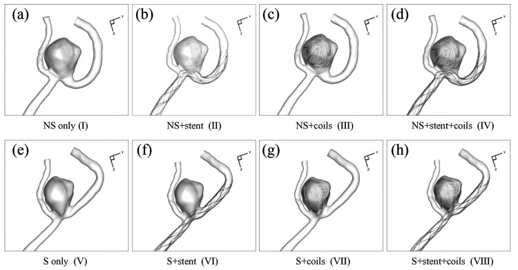
Eight CFD simulation models were constructed to investigate the aneurysmal hemodynamic changes, including (NS stands for not straightened; S stands for straightened) (I) NS only model: the aneurysm sac and parent artery model without vessel deformation; (II) NS+stent model: NS only model with deployed stent; (III) NS+coils model: NS only model with deployed coils; (IV) NS+stent+coils model: NS only model with deployed stent and coils; (V) S only model: the aneurysm sac and deformed parent artery model; (VI) S+stent model: S only model with deployed stent; (VII) S+coils model: S only model with deployed coils; (VIII) S+stent+coils model: S only model with deployed stent and coils. In these eight models, model (I) was the real pre-treatment model, while model (VIII) was the real post-treatment model. All other 6 models were hypothetical models constructed to evaluate hemodynamic modifications caused by stenting, coiling and stent-induced parent artery straightening, respectively.
Patient description and aneurysm model
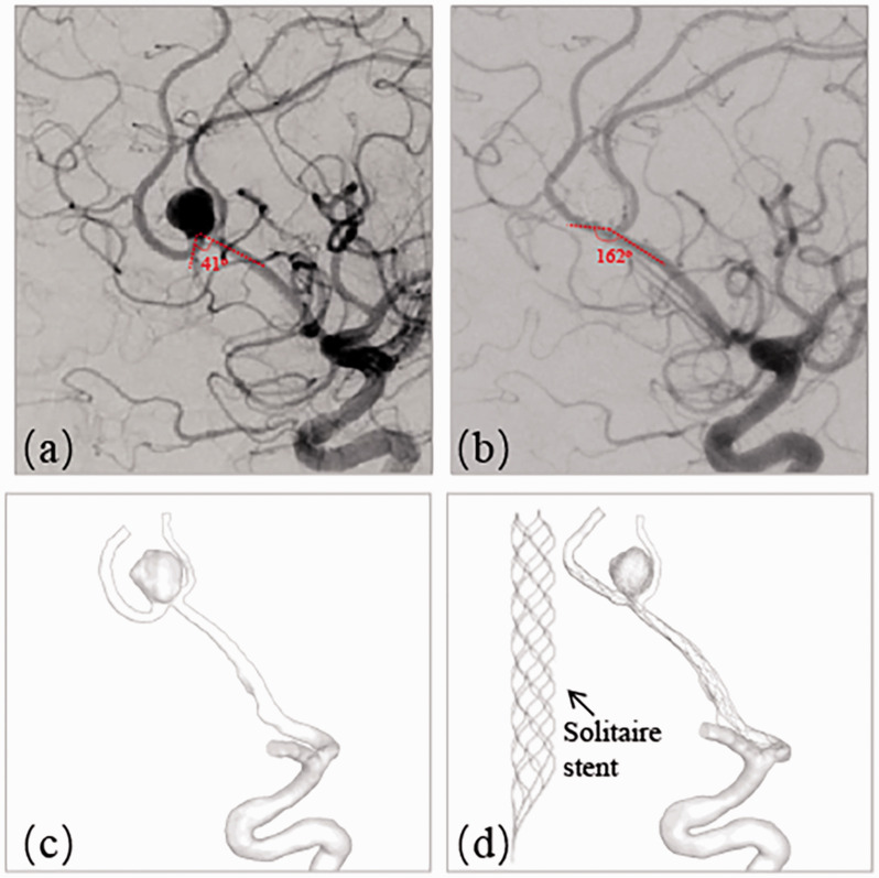
A patient with a left incidentally found unruptured pericallosal and callosomarginal artery bifurcation aneurysm (distal anterior cerebral artery, A2/3 segment), who was treated with SACE in real life, was included in this study. This aneurysm represented a diverse range of intracranial distal bifurcation aneurysms with deformation of adjacent parent artery after stent deployment. The pre- and post-treatment angiograms are shown in Figure 1(a) (pre) and (b) (post), where the angle between A2 and A3 was changed from 41° to 162° due to the straightening of the Solitaire stent (Medtronic, Irvine, California) deployment with the size of 4 mm20 mm. The aneurysm size was 6.88 mm and the neck diameter was 4.88 mm. Angiography immediately after stent deployment and coiling showed complete occlusion of the aneurysm.
Figure 1.
A left A2-A3 unruptured bifurcation aneurysm treated with stent-assisted embolization representing large angular change. (a) Pre-treatment angiography showing the angle of 41° between A2 and A3; (b) Post-treatment angiography revealing the angle change into 162°; (c) Segmented aneurysm and vessel geometry of pre-treatment; (d) Deformed aneurysm and vessel geometry of post-treatment by a Solitaire stent (4mm20mm).
3D rotational angiographic images were obtained and 3D segmentation and isolation of the region of interest were performed through the open source software, VMTK (www.vmtk.org) and the segmented geometry prior to the treatment is shown in Figure 1(c). In order to perform the simulation of stent-assisted remodeling and coil deployment, part of adjacent parent artery with the aneurysm sac was isolated from its whole parent vessel using Geomagic tool (Geomagic Inc., Morrisville, North Carolina). The total volume of the aneurysm was 172.93 mm3. This retrospective study was approved by our institutional review board with consent waived by the IRB.
Finite-element method modeling of coiling and stent deployment
Solitaire stent was generated virtually using SolidWorks (Dassault Systems, SolidWorks Corp., MA) as shown in Figure 1(d) and transferred into FEM software ABAQUS v6.14 (SIMULIA, Providence, RI) to perform the remodeling of the aneurysm with adjacent parent vessels. Meanwhile, helical and frame coils were generated in MATLAB (MathWorks, Natick, MA) and the shape of the coils was simplified by using a centerline.14 A continuous toroidal structure in 3D shape was assumed for the coils9,15 and then the coils were swept to 3D configuration after deployment in the aneurysm sac.
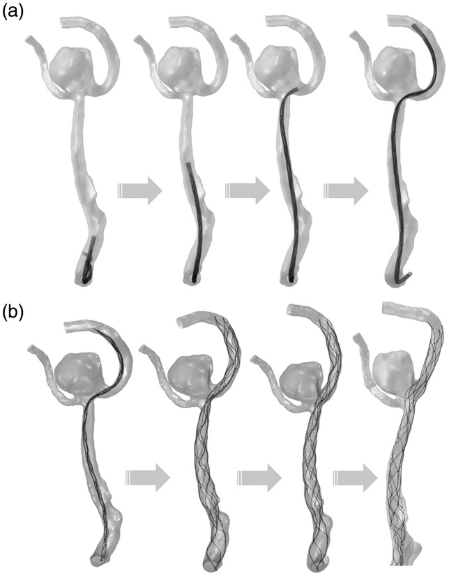
The FEM-based workflow for stent deployment modeling was conducted in ABAQUS/Explicit v6.14, where the stent was modeled as Nitinol alloy and the material properties were obtained from literature16,17, as shown in Table 1 in reference.14 The simulation procedures consisted of three steps: crimping, delivery and releasing. Firstly, the stent crimping was performed and the crimped result was used as the initial condition for the delivery process through the pre-defined function in ABAQUS. Secondly, a delivery path was generated with central points of the cross-sections of the blood vessel. Then the crimped stent within a microcatheter was delivered through the path to the orifice of the aneurysm, according to the process of delivery of the stent from the real clinical treatment. Finally, the stent was deployed in parent artery which was assumed to be rigid wall for NS models (I-IV) and deformable wall for S models (V-VIII). It is worth noting that in S models the vessel and aneurysm were deformed by the expanding and stretching force of the stent during the delivery process. Based on the deployment results, deformed vessel and aneurysm geometries were exported for subsequent CFD simulations. During the whole FEM simulation, a “general contact” algorithm in ABAQUS was used for the complex interactions involved in the stent delivery and deployment procedures, with a friction coefficient value of 0.15.9
As described above, during FEM analysis, the parent vessel was modeled as rigid wall in NS models and deformable wall in S models. In the latter case, Mooney-Rivlin stress-strain constitutive relationship was implemented to simulate the hyperelastic behavior of vessel wall.18 A set of parameter values from human cerebral artery wall were adopted, where the parameters were chosen as C1 = 0.174MPa, C2 = 1.88MPa.18 The cerebral arterial wall and aneurysmal wall were modeled as membrane element with thickness of 0.3 mm19 and 0.2 mm,20 respectively. After the stent deployment, five coils including two framing coils and three helical coils were deployed into the aneurysm sac and all the coils were swept into 3D solid model using ABAQUS with the real diameters of coils as described previously.14 In the end, the surface-based aneurysm and vessel geometry model with the 3D representation of the stent and coils were used for the subsequent CFD analysis.
CFD simulation
The computational model was meshed with polyhedral grids with size of 0.1 mm for the aneurysm and vessel, 0.03mm for the stent and 0.1mm for the coils using STAR-CCM+ meshing tool (CD Adapco, Melville, NY). Incompressible Navier-Stokes equations under steady flow conditions were solved with the finite volume CFD solver, STAR-CCM+. The mean flow rate for the internal carotid artery inlet was 4.6 ml/s and used as the inlet boundary condition.21 Traction-free boundary conditions were applied at all outlets and the mass flow rate through each outlet vessel was set to be proportional to the cube of its diameter based on the principle of optimal work.22 With a density of 1056 kg/m3 and a viscosity of 0.0035 N·s/m2, the blood was modeled as a Newtonian fluid material23 and the vessel walls were modeled as rigid wall with no-slip boundary conditions.24
For qualitative analysis, the aneurysmal flow streamlines, velocity magnitude at the cutting planning, iso-velocity surface (to measure high flow region around aneurysmal neck plane) and wall shear stress (WSS) were visualized. Iso-velocity surface was the surface with equal velocity. WSS indicated the frictional force between blood and arterial wall inner surface and was found to have an essential influence to the aneurysm initiation, growth and rupture.7,25,26 For quantitative analysis, the sac-averaged velocity, high flow volume using iso-velocity surface (>0.5 m/s) and sac-averaged WSS were calculated, using pre-treatment model as baseline (100%).
Results
Finite-element method modeling of coiling and stent deployment
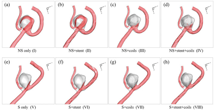
Figure 2 shows the eight designed models in this study from the stent and coil deployment. Models I-IV were the NS models without parent artery straightening, while Models V-VIII were S models, where stent deployment straightened the parent vessel and also changed aneurysm geometry due to the stent deployment. The stent and coil deployment processes and the corresponding results in Model VIII mimicked the real clinical treatment procedures and deployment results. The five coils’ deployment sequence in models III, IV, VII, and VIII followed the sequence in the real coil deployment. The stent deployment in models VI and VIII followed the real stent deployment, while hypothetical stent deployments in models II and VI achieved good expansion and apposition of the stent to the arterial wall.
Figure 2.
Eight CFD simulation models in current study design: (a) NS only model (I); (b) NS+stent model (II); (c) NS+coils model (III); (d) NS+stent+coils model (IV); (e) S only model (V); (f) S+stent model (VI); (g) S+coils model (VII); (h) S+stent+coils model (VIII).
Figure 3 details the stent deployment procedures in the simulation, including the stent delivery (Figure 3(a)) and the stent releasing (Figure 3(b)), which straightens the parent vessel and also changes aneurysm geometry. It takes about 10 hours to perform the stent releasing, 5 hours to perform the coils releasing and 2 hours to perform CFD simulation.
Figure 3.
Flow chart for stent deployment simulation: (a) Solitaire stent delivery step with microcatheter; (b) self-expansion process of Solitaire stent to generate vessel and aneurysm deformation.
Qualitative analysis
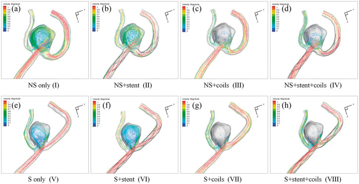
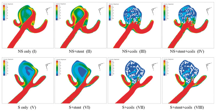
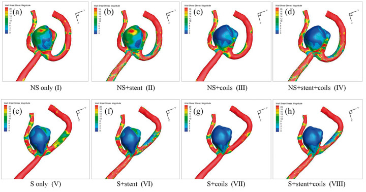
Hemodynamics of the eight IA models are plotted in Figures 4 to 7, which represent the streamlines with color-code velocity (Figure 4), velocity magnitude at the middle cutting plane (Figure 5), iso-velocity surface (Figure 6) and WSS (Figure 7), respectively.
Figure 4.
Streamlines with color-code velocity magnitude in the eight models:(a) NS only model (I); (b) NS+stent model (II); (c) NS+coils model (III); (d) NS+stent+coils model (IV); (e) S only model (V); (f) S+stent model (VI); (g) S+coils model (VII); (h) S+stent+coils model (VIII).
Figure 5.
Velocity magnitude contour at the cutting plane results in the eight models: (a) NS only model (I); (b) NS+stent model (II); (c) NS+coils model (III); (d) NS+stent+coils model (IV); (e) S only model (V); (f) S+stent model (VI); (g) S+coils model (VII); (h) S+stent+coils model (VIII).
Figure 6.
Iso-velocity surface results in the eight models: (a) NS only model (I); (b) NS+stent model (II); (c) NS+coils model (III); (d) NS+stent+coils model (IV); (e) S only model (V); (f) S+stent model (VI); (g) S+coils model (VII); (h) S+stent+coils model (VIII).
Figure 7.
WSS distribution in the eight models: (a) NS only model (I); (b) NS+stent model (II); (c) NS+coils model (III); (d) NS+stent+coils model (IV); (e) S only model (V); (f) S+stent model (VI); (g) S+coils model (VII); (h) S+stent+coils model (VIII).
From the streamlines in Figure 4, we observed 1) less flow in the S models, compared with the corresponding NS models; 2) coils blocked most flow into the aneurysm sac in both NS models and S models. These observations echo well with the visualization of velocity magnitude in the middle cutting plane in Figure 5 and the iso-velocity surface in Figure 6. Furthermore, Figures 5 and 6 demonstrate that adding stent increases the flow into the aneurysm sac (e.g., model II vs. model I, model IV vs. model III, model VI vs. model V, and model VIII vs. model VII). From Figure 6, we observe that vessel straightening has more profound effect in the aneurysm flow reduction than coiling, while stenting has adverse effect in the flow reduction.
Similar phenomena can also be observed in WSS distributions as shown in Figure 7. Overall, due to the volumetric flow reduction by coiling and straightening of parent vessel, WSS was significantly decreased in all coiled models of NS models and all S models. WSS was increased after stenting, obviously observed from model II and model I.
Quantitative analysis
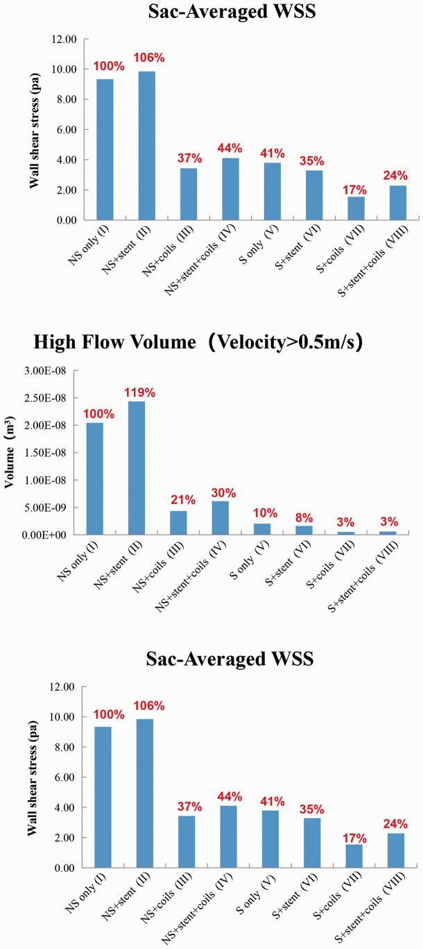
The sac-averaged velocity, high flow volume and sac-averaged WSS magnitude in the aneurysms are plotted in Figure 8. Taking model I as the baseline (100%), the sac-averaged velocity was increased to 112% in model II after stenting, and was decreased to 36% and 42% in the model III and model IV. For the S models, the sac-averaged velocity reduced to 45%, 39%, 12% and 13% in model V, model VI, model VII and model VIII, respectively. From these quantifications, coiling decreased 64% and vessel straightening decreased 55% of the sac-averaged velocity, while stenting increased 12% and the combination of coiling and vessel straightening reduced the most, 88% in sac-averaged velocity based on the NS only model.
Figure 8.
Quantitative comparison of Sac-Averaged Velocity,High Flow Volume (Velocity>0.5 m/s) and Sac-Averaged WSS in the eight models: (a) NS only model (I); (b) NS+stent model (II); (c) NS+coils model (III); (d) NS+stent+coils model (IV); (e) S only model (V); (f) S+stent model (VI); (g) S+coils model (VII); (h) S+stent+coils model (VIII).
For the NS models, the high flow volume (velocity>0.5 m/s) inside the aneurysm sac was increased to 119% in model II, whereas the high flow volume was decreased to 21%, 30% in models III and IV. For the S models, the high flow volume was reduced to 10%, 8%, 3% and 3% in models V to VIII, respectively. Thus coiling decreased 79% and vessel straightening decreased 90% of high flow volume, while stenting increased 19% and the combination of coiling and vessel straightening reduced 97% of that.
The sac-averaged WSS on the aneurysm sac wall increased to 106% in model II, and decreased to 37%, 44% in model III and IV. In the S models, the average WSS of aneurysmal sac wall with parent artery straightening reduced to 41%, 35%, 17% and 24% in model IV to VIII, respectively. In summary, coiling alone decreased 63% and vessel straightening decreased 59% for sac-averaged WSS, while stenting alone increased 6% and the combination of coiling and vessel straightening decreased 83% of WSS, compared to the baseline.
Discussions
Applying a high-fidelity FEM-based simulation method, this study provided scientific proof-of-concept on hemodynamic modifications for the stent-induced straightening technique. Comparing the hemodynamic modification effect among stent-induced artery straightening, coiling and stenting, stent-induced straightening had the most significant effect on high flow volume reduction. Stent-induced artery straightening plus coil embolization treatment strategy had the best performance on hemodynamic modifications and may reduce the recurrent rate, whereas stenting alone may generate adverse effect on hemodynamic modifications.
In SACE treatment of IAs, the original purpose of the stent was to provide the scaffold to avoid coil herniation. In clinical practice, the stent also induced parent vessel straightening.11,27,28 Gao et al.,27 revealed that stent placement increased the inflow angle from 101.5° to 119.8° post-procedurally and to 137.3° at follow-up and the angular change was greater in distal-versus-proximal vessels (anterior cerebral>middle cerebral>basilar>internal carotid artery). Huang et al.28 demonstrated an average angle change of 29.95° for 20 anterior communicating artery aneurysms. Reported by Kono et al.,11 stent placement straightened vessels by 12.9° on average. In current study, the A2-A3 angle was changed from 41° to 162°, and the angular change was significantly larger than the reported angle changes, mainly due to the position of the distal artery in this particular aneurysm case in current study.12,27
In this study, for the first time we developed a high-fidelity FEM-based method to capture the parent vessel straightening effect in the SACE treatment strategy for IAs. In the S+stent simulation of current study, the cerebral arterial wall was non-rigid and modeled as Mooney-Rivlin stress-strain constitutive relationship using human cerebral artery wall property, while the Solitaire stent was modeled as nitinol super-elasticity material property. The parent vessel was straightened during the stent releasing procedure by the stent internal force from the stent crimping and delivery steps. At the same time, the aneurysm sac was also deformed accordingly in the post-stent simulation of current study. High-fidelity FEM-based method was previously used in the stent deployment of IAs,29 however in their study the vessel wall was assumed as rigid and thus could not capture the vessel and aneurysm wall deformation. In order to investigate the hemodynamic effect between stent struts and straightening, Kono et al.,11 applied manual registration method to obtain straightened aneurysm-vessel geometry model for subsequent CFD simulations by fusing pre-operative aneurysm sac model and post-operative straightened parent vessel model. As stated by the authors, structural simulation or high-fidelity FEM-based method of stent deployment would be better. It is also worth mentioning that in our wall structure simulation, not only the parent vessel was straightened, but also the aneurysm sac geometry was deformed due to the parent vessel deformation, which could not be captured with the manual registration method. In addition, the coil deployment was vital for the hemodynamic simulation predictions for aneurysms treated with SACE. Whereas, most CFD studies on SACE treated aneurysms did not take into account the coiling for the simulations because of technical difficulties.11,30
Through CFD simulations of the eight NS and S models, we demonstrated that coiling alone and stent-induced straightening reduced 64% and 55% of sac-averaged velocity magnitude, 79% and 90% of high flow volume, 63% and 59% of WSS, respectively. Sac-averaged velocity reduction represented the flow stasis inside the aneurysm sac and thus a measurement for the possibility of aneurysmal thrombosis, and larger high flow volume indicated the likelihood of aneurysm recurrence, while WSS was the measurement of the flow condition where aneurysmal wall was exposed and aberrant WSS (abnormal high or low) might cause aneurysm grow and even rupture after treatment. From our simulation results, stent-induced straightening should have a larger contribution than coiling in reducing aneurysm recurrence rate in this aneurysm (90% vs. 79% in high flow volume reduction). Furthermore, this study revealed that stenting alone caused adverse effect on hemodynamics, increasing 12%, 19% and 6% of velocity, high flow region and WSS by comparing NS only model and NS+stent models, respectively. Among all these models, S+coils model had the best hemodynamic effects, reducing 88%, 97%, and 83% of velocity, high flow region and WSS. However, S+coils model was only a hypothetical scenario, thus the S+stent+coils model had the best hemodynamic alteration effects among the realistic models, namely NS+coils model (model III), S+stent model (model VI) and S+stent+coils model (model VIII), with 64% vs. 61% vs. 87%, 79% vs. 92% vs. 97%, 63% vs. 65% vs. 76% in reduction of velocity, high flow region and WSS.
In the well-designed study,11 the authors investigated the hemodynamic effect between stent struts and straightening and demonstrated stent strut had double effect on flow velocity reduction than straightening of vessels. While in current study, instead of decreasing flow and WSS, we demonstrated that stenting had adverse hemodynamic alteration effect. Comparing current study with their study,11 we should be aware that the aneurysm in our study was a A2-A3 distal bifurcation aneurysm, while all 16 aneurysms in the study11 were sidewall IAs. For bifurcation IAs, it was entirely possible that stenting might generate elevated flow inside the aneurysm sac because the stent struts narrowed the inflow jet typically observed in bifurcation IAs and thus produced stronger inertia force, elevating flow into the aneurysm sac and a similar conclusion was also found in another study.31 While for sidewall IAs, most aneurysms had cavity flow and stent struts blocked the flow into the aneurysm sac and thus typically stenting reduced hemodynamics into the aneurysm.11 Straightening bifurcation IAs caused larger inflow angle change and thus should generate more profound hemodynamic effect than sidewall IAs. There were positive correlations between pre-operative inflow angles and changes in flow angles by stent placement (r = 0.69), and between pre-operative inflow angles and inflow reduction (r = 0.53).11
Some studies32,33 have indicated that antiplatelet therapy will change the viscosity of blood, which is a crucial parameter when performing CFD simulation. The non-Newtonian blood viscosity model predict lower threshold of WSS values and slightly severe gradients. Low WSS values on the aneurysm wall are known to be an important rupture risk factor, and severe gradients do contribute to the aneurysm growth via a pathological route.34 The influence of antiplatelet therapy on the viscosity of blood will be taken into consideration in our future study. Several limitations in this study should be noted. First, only one aneurysm case was used in current study and thus the conclusion from this study might not be generalized. Since the current manuscript focuses on developing reliable and practical methods for simulation of straightening of parent vessels for SACE treatment of intracranial aneurysms, more cases research will be conducted in the future. Second, the validation of the stent-induced straightening was not performed, although the simulation result of vessel and aneurysm deformation was confirmed with the post-treatment angiographic images and also the specific cerebral arterial material properties were used in the simulations. Third, only the Solitaire stent used in this patient is a laser-cut stent with closed cell. Fourth, only a pericallosal aneurysm was chosen. Although aneurysms at the bifurcation of the pericallosal margin are slightly less common than aneurysms at bifurcations, such as anterior communicating aneurysm, middle cerebral aneurysm, or basilar apex aneurysm, the pericallosal marginal aneurysm selected in this study is also a typical bifurcation. In the simulation, the bifurcation aneurysm was transformed into a lateral wall aneurysm due to the metal memory effect of the stent after stenting, which can better reflect the blood flow remodeling effect of the stent. In the future, we will investigate the stiffness and the performance of strengthening the vessels from different aneurysm locations of different intracranial stents with variable properties.
Conclusions
This study provided a scientific proof-of-concept on hemodynamic modifications for the stent-induced straightening technique. Comparing the hemodynamic modification effect among stent-induced artery straightening, coiling, and stenting, stent-induced straightening had the most significant effect in high flow volume reduction. Stent-induced artery straightening plus coil embolization treatment strategy had the best performance on hemodynamic modifications and may reduce the recurrent rate, whereas stenting alone may generate adverse effect on hemodynamic modifications. This technique may be recommended as a novel strategy to treat distal cerebral bifurcation aneurysms.
Footnotes
Declaration of conflicting interests: The author(s) declared no potential conflicts of interest with respect to the research, authorship, and/or publication of this article.
Funding: The author(s) disclosed receipt of the following financial support for the research, authorship, and/or publication of this article: This work as supported by National Natural Science Foundation of China (grant no. 11802113, 81371308, and 81771242).
ORCID iDs: Xiaochang Leng https://orcid.org/0000-0002-0041-7602
Hailin Wan https://orcid.org/0000-0001-6761-4603
Yeqing Jiang https://orcid.org/0000-0001-7558-917X
References
- 1.Rinkel GJ. Natural history, epidemiology and screening of unruptured intracranial aneurysms. Rev Neurol (Paris) 2008; 164: 781–786. [DOI] [PubMed] [Google Scholar]
- 2.Rinkel GJ, Djibuti M, Algra A, et al. Prevalence and risk of rupture of intracranial aneurysms: a systematic review. Stroke 1998; 29: 251–256. [DOI] [PubMed] [Google Scholar]
- 3.Kole MK, Pelz DM, Kalapos P, et al. Endovascular coil embolization of intracranial aneurysms: important factors related to rates and outcomes of incomplete occlusion. J Neurosurg 2005; 102: 607–615. [DOI] [PubMed] [Google Scholar]
- 4.Raymond J, Guilbert F, Weill A, et al. Long-term angiographic recurrences after selective endovascular treatment of aneurysms with detachable coils. Stroke 2003; 34: 1398–1403. [DOI] [PubMed] [Google Scholar]
- 5.Johnston SC, Dowd CF, Higashida RT, et al. Predictors of rehemorrhage after treatment of ruptured intracranial aneurysms: the Cerebral Aneurysm Rerupture After Treatment (CARAT) study. Stroke 2008; 39: 120–125. [DOI] [PubMed] [Google Scholar]
- 6.Lubicz B, Bandeira A, Bruneau M, et al. Stenting is improving and stabilizing anatomical results of coiled intracranial aneurysms. Neuroradiology 2009; 51: 419–425. [DOI] [PubMed] [Google Scholar]
- 7.Xiang J, Ma D, Snyder KV, et al. Increasing flow diversion for cerebral aneurysm treatment using a single flow diverter. Neurosurgery 2014; 75: 286–294. [DOI] [PubMed] [Google Scholar]
- 8.Ma D, Xiang J, Choi H, et al. Enhanced aneurysmal flow diversion using a dynamic push-pull technique: an experimental and modeling study. Am J Neuroradiol 2014; 35: 1779–1785. [DOI] [PMC free article] [PubMed] [Google Scholar]
- 9.Damiano R, Ma D, Xiang J, et al. Finite element modeling of endovascular coiling and flow diversion enables hemodynamic prediction of complex treatment strategies for intracranial aneurysm. J Biomech 2015; 48: 3332–3340. [DOI] [PMC free article] [PubMed] [Google Scholar]
- 10.Tremmel M, Xiang J, Natarajan SK, et al. Alteration of intra-aneurysmal hemodynamics for flow diversion using enterprise and vision stents. World Neurosurg 2010; 74: 306–315. [DOI] [PMC free article] [PubMed] [Google Scholar]
- 11.Kono K, Shintani A and Terada T. Hemodynamic effects of stent struts versus straightening of vessels in stent-assisted coil embolization for sidewall cerebral aneurysms. PLoS One 2014; 9(e108033): 1–7. [DOI] [PMC free article] [PubMed] [Google Scholar]
- 12.Gao B, Baharoglu MI, Cohen AD, et al. Y-stent coiling of basilar bifurcation aneurysms induces a dynamic angular vascular remodeling with alteration of the apical wall shear stress pattern. Neurosurgery 2013; 72: 617–629. [DOI] [PubMed] [Google Scholar]
- 13.Gao B, Baharoglu MI, Malek AM. Angular remodeling in single stent-assisted coiling displaces and attenuates the flow impingement zone at the neck of intracranial bifurcation aneurysms. Neurosurgery 2013; 72: 739–748. [DOI] [PubMed] [Google Scholar]
- 14.Leng X, Wang Y, Xu J, et al. Numerical simulation of patient-specific endovascular stenting and coiling for intracranial aneurysm surgical planning. J Transl Med 2018; 16: 208. [DOI] [PMC free article] [PubMed] [Google Scholar]
- 15.Babiker MH, Chong BW, Gonzalez LF, et al. Finite element modeling of embolic coil deployment: multifactor characterization of treatment effects on cerebral aneurysm hemodynamics. J Biomech 2013; 46: 2809–2816. [DOI] [PubMed] [Google Scholar]
- 16.Reedlunn B, Daly S and Shaw J. Tension-torsion experiments on superelastic shape memory alloy tubes. In: ASME 2012 conference on smart materials, adaptive structures and intelligent systems, 2012, pp. 213–222.
- 17.Zhu P, Brinson LC, Peraza-Hernandez E, et al. Comparison of three-dimensional shape memory alloy constitutive models: finite element analysis of actuation and superelastic responses of a shape memory alloy tube. In: ASME 2013 Conference on smart materials, adaptive structures and intelligent systems, 2013, pp. 16–18.
- 18.Zhang H, Jiao Y, Johnson E, et al. Modelling anisotropic material property of cerebral aneurysms for fluid–structure interaction simulation. Comput Methods Biomech Biomed Eng Imaging Visual 2013; 1: 164–174. [Google Scholar]
- 19.Tóth M, Nádasy GL, Nyáry I, et al. Are there systemic changes in the arterial biomechanics of intracranial aneurysm patients? Pflügers Archiv 2000; 439: 573–578. [DOI] [PubMed] [Google Scholar]
- 20.Eriksson T, Kroon M, Holzapfel GA. Influence of medial collagen organization and axial in situ stretch on saccular cerebral aneurysm growth. J Biomech Eng 2009; 131: 101010–101017. [DOI] [PubMed] [Google Scholar]
- 21.Fahrig R, Nikolov H, Fox AJ, et al. A three-dimensional cerebrovascular flow phantom. Med Phys 1999; 26: 1589–1599. [DOI] [PubMed] [Google Scholar]
- 22.Oka S, Nakai M. Optimality principle in vascular bifurcation. Biorheology 1987; 24: 737–751. [DOI] [PubMed] [Google Scholar]
- 23.Xiang J, Yu J, Snyder KV, et al. Hemodynamic–morphological discriminant models for intracranial aneurysm rupture remain stable with increasing sample size. J Neurointervent Surg 2016; 8: 104. [DOI] [PMC free article] [PubMed] [Google Scholar]
- 24.Cebral JR, Castro MA, Appanaboyina S, et al. Efficient pipeline for image-based patient-specific analysis of cerebral aneurysm hemodynamics: technique and sensitivity. IEEE Trans Med Imaging 2005; 24: 457–467. [DOI] [PubMed] [Google Scholar]
- 25.Meng H, Tutino VM, Xiang J, et al. High WSS or low WSS? Complex interactions of hemodynamics with intracranial aneurysm initiation, growth, and rupture: toward a unifying hypothesis. AJNR Am J Neuroradiol 2014; 35: 1254–1262. [DOI] [PMC free article] [PubMed] [Google Scholar]
- 26.Boussel L, Rayz V, McCulloch C, et al. Aneurysm growth occurs at region of low wall shear stress: patient-specific correlation of hemodynamics and growth in a longitudinal study. Stroke 2008; 39: 2997–3002. [DOI] [PMC free article] [PubMed] [Google Scholar]
- 27.Gao B, Baharoglu MI, Cohen AD, et al. Stent-assisted coiling of intracranial bifurcation aneurysms leads to immediate and delayed intracranial vascular angle remodeling. AJNR Am J Neuroradiol 2012; 33: 649–654. [DOI] [PMC free article] [PubMed] [Google Scholar]
- 28.Huang QH, Wu YF, Xu Y, et al. Vascular geometry change because of endovascular stent placement for anterior communicating artery aneurysms. Am J Neuroradiol 2011; 32: 1721. [DOI] [PMC free article] [PubMed] [Google Scholar]
- 29.Ma D, Dumont TM, Kosukegawa H, et al. High fidelity virtual stenting (HiFiVS) for intracranial aneurysm flow diversion: in vitro and in silico. Ann Biomed Eng 2013; 41: 2143–2156. [DOI] [PMC free article] [PubMed] [Google Scholar]
- 30.Kono K, Terada T. Hemodynamics of 8 different configurations of stenting for bifurcation aneurysms. AJNR Am J Neuroradiol 2013; 34: 1980–1986. [DOI] [PMC free article] [PubMed] [Google Scholar]
- 31.Jeong W, Han MH, Rhee K. The hemodynamic alterations induced by the vascular angular deformation in stent-assisted coiling of bifurcation aneurysms. Comput Biol Med 2014; 53: 1–8. [DOI] [PubMed] [Google Scholar]
- 32.Lee C-H, Jung K-H, Cho DJ, et al. Effect of warfarin versus aspirin on blood viscosity in cardioembolic stroke with atrial fibrillation: a prospective clinical trial. BMC Neurol 2019; 19: 82. [DOI] [PMC free article] [PubMed] [Google Scholar]
- 33.Nwose E, Burkowski E. Algorithm for whole blood viscosity: implication for antiplatelet bleeding risk assessment. Aust J Med Sci 2013; 34: 50–55. [Google Scholar]
- 34.el Gibaly A, El-Bassiouny OA, Diaa O, et al. Effects of non-Newtonian viscosity on the hemodynamics of cerebral aneurysms. Appl Mech Mater 2016; 819: 366–370. [Google Scholar]


