Abstract
The design of a headspace pressure-monitoring reactor for measuring the uptake/evolution of gas in gas–liquid chemical transformations is described. The reactor features a parallel setup with ten-reactor cells, each featuring a low working volume of 0.2–2 ml, a pressure capacity from 0 to 150 PSIa, and a high sensitivity pressure transducer. The reactor cells are composed of commercially available disposable thick-walled glassware and compact monolithic weld assemblies. The software interface controls the reactor temperature while monitoring pressure in each of the parallel reactor cells. Reactions are easy to set up and yield high-density gas uptake/evolution data. This instrument is especially well suited to acquire quantitative time-course data for reactions with small quantities of gas consumed or produced.
I. INTRODUCTION
Liquid-phase chemical reactions that use gaseous reagents (e.g., O2, H2, CO, ethylene, and CO2) play an important role in laboratory and industrial chemical syntheses. Analysis of reaction kinetics is crucial for the development of these processes; however, quantitative data acquisition can be complicated by perturbation of the reaction mixture when sampling from a sealed system (e.g., withdrawing aliquots) or due to poor gas–liquid mixing [e.g., during nuclear magnetic resonance (NMR) spectroscopic analysis]. Monitoring the gas consumption or evolution provides an appealing non-intrusive method to bypass these limitations, and it has been successfully used to analyze diverse gas–liquid chemical reactions, including hydrogenations,1 artificial photosynthesis,2 carbonylations,3 ethylene polymerization,4 ammonia borane dehydrogenation,5 aerobic oxidations,6 and hydroformylations.7
Monitoring reaction headspace pressure is especially useful in quantifying consumption or evolution of small quantities of gas. For example, liquid-phase catalytic aerobic oxidation reactions, such as those recently investigated in our lab and by others,8,9 utilize relatively dilute reaction concentrations (50–300 mM) and commonly consume only 0.5 equivalents of O2, resulting in relatively small quantities of gas consumed. Many commercially available reactors are available, and these are typically designed to accommodate high gas pressures (e.g., 1500–3000 PSIa). The large dynamic range of these systems leads to a low resolving power for analysis of reactions that consume small amounts of gas.1,7,10,11
In the present report, we describe a low-volume, multi-channel reactor system for parallel analysis of headspace pressure. It is compatible with relatively low pressures and capable of analyzing reactions that consume or evolve small quantities of gas. The reactor described here complements previously reported reactor systems for analysis of small-scale gas uptake/evolution reactions based on the measurement of gas flow rates,12,13 differential pressures,14 bubble counts,15 and headspace volume16 or pressure2,6,10,11 changes. Key criteria incorporated into the present reactor design were not collectively incorporated into previously reported systems: (1) compatible with pressure ranges of 0–150 PSIa; (2) high sensitivity, allowing for the quantitative detection of gas uptake/evolution in amounts of ≤0.2 μmol; (3) small reaction volumes (0.2–2 ml) that minimize reagent quantities need to analyze the reactions; (4) compatible with disposable reaction vessels that facilitate setup, minimize gas leakage, and enhance user-friendly operation by non-specialists; (5) a compact, parallel design to accommodate up to ten simultaneous reactions; (6) allow for safe analysis of aerobic oxidation reactions, with little or no potential for fire propagation and/or explosion; and (7) simple construction, suitable for fabrication in a general-use machine shop. The reactor described herein meets these criteria, and a full description of the reactor cell, heating block, electrical hardware, and control software is provided. Representative data from four experimental applications of the reactor are provided to illustrate the types of data that may be acquired. Full documentation of construction information, lists of parts, and experimental details are provided in the supplementary material.
II. RESULTS AND DISCUSSION
A. Reactor cell
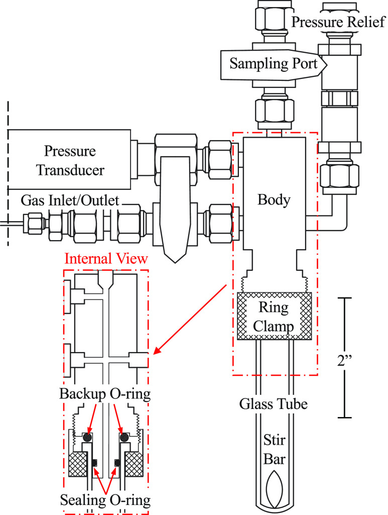
We designed a reactor cell head with an affixed pressure transducer that can be mounted onto commercially available, disposable, 10 ml thick-walled microwave tubes (Fig. 1). Because the total pressure change is inversely correlated with the reactor headspace volume, the headspace was minimized to increase the gas uptake/evolution resolution. A monolithic weld assembly was built to minimize the headspace and the number of junctions that could contribute to gas leaks. A cylindrical stainless steel body with internal cavities was welded to four thick-walled stainless steel arms (Fig. 1, internal view). Stainless steel arms were connected via tube fittings to a gas inlet/outlet port, a pressure transducer, a sampling port with a septum, and a pressure relief port. The sampling and gas inlet/outlet ports incorporate quarter turn valves to open and close the ports before and after injection/sampling and gas filling/backfilling. The pressure transducer features stainless steel internal exposed parts for high chemical resistance and a pressure range from 0 to 150 PSIa. The pressure is detected via a 4–20 mA process loop, minimizing the voltage (and corresponding spark hazard) at the transducer. A pressure relief check valve was included, fitted with a chemical-resistant Simriz® O-ring with a set pressure release at 165 PSIa.
FIG. 1.
Diagram of reactor cell assembly: The reactor cell incorporates a thick-walled glass microwave tube, stainless steel custom body, pressure transducer (0–150 PSIa range, 4–20 mA), gas inlet/outlet port, sampling port, and pressure relief port. Reactor internal volume is 13.6 ± 0.1 ml with a reaction volume capacity of 0.2–2 ml. The glass tube is sealed by compression of a chemical-resistant O-ring on the internal walls of the tube.
The bottom of the assembly features two O-rings. The sealing O-ring compresses against the internal glass walls of the pressure tube, making a gas tight seal. The backup O-ring provides a secondary backup seal and compression to prevent cracking as the tube is affixed to the reactor head. A brass screw clamp is used to secure the glass tube in place by pressing against the underside of the lip of the glass tube. Assembly is simple, and the tube slides over the sealing O-ring and is secured to the reactor by hand-tightening the screw clamp.
The resulting reactor cell assembly is equipped to monitor small-scale gas uptake/evolution from chemical reactions. The 8 in. tall reactor cell holds a constant pressure for an extended period of time (see Fig. S28 of the supplementary material). The combination of small internal volumes (13.6 ± 0.1 ml) and sensitive electronics allows for the measurement of uptake/evolution as small as 0.18 μmol of gas (assuming ideal gas behavior, a 2 ml reaction volume, and stable temperature control). The lowest detectable pressure change is 5.7 × 10⁻³ PSI.
B. Parallel design
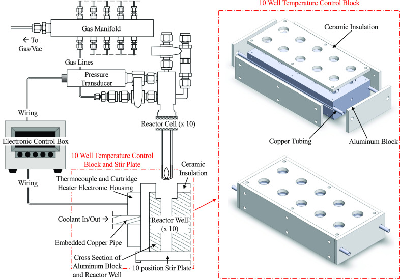
We designed a multi-well temperature control block and stir plate assembly that accepts up to ten of the aforementioned reactor cells (Fig. 2). The aluminum temperature control block features two cartridge heaters, a thermocouple, copper cooling tubes, and external insulation. The 1000 W cartridge heaters and copper cooling tubes were installed symmetrically such that all wells maintain the same temperature. Glastherm® HT solid insulation was mounted on the exposed sides of the block to mitigate uncontrolled thermal heat loss. To prevent runaway heating, the aluminum block is embedded with two thermal fuses that stop all heating at 182 °C. The entire temperature control block fits on top of a commercially available ten-position stir plate.
FIG. 2.
Schematic overview of the ten position parallel setup, with only one reactor cell shown for clarity. A temperature-controlled aluminum block (right) is placed on a multi-position stir plate. All reactors are fed gas by a ten-way manifold (upper left). An electronic control box (center left) controls the temperature and measures the pressure.
Each reactor cell was connected to a gas manifold and electronic box. Teflon 1/16 in. tubing connects the gas manifold to the inlet/outlet ports of the reactor cells. The shared gas manifold leads to a three-way valve connected to a gas regulator and a chemical-resistant diaphragm vacuum pump for gas fills and backfills of the reactor cells. M12 cables connect the pressure transducers to the electronic control box. The tubing and cables are flexible and easily removed, allowing the user to choose the number of desired reactors for simultaneous runs.
C. Electronics and software
The heating block and pressure transducers are controlled/monitored by using an electronic control box (Fig. 2, center left). The signals from the pressure transducers are 4–20 mA process control loops, which are digitized using three four-channel 16-bit low-noise analog-to-digital converters. Although only ten reactors are monitored simultaneously, there are 3 × 4 = 12 digitization channels. A K-type thermocouple was used with a dedicated integrated circuit (see the supplementary material for details) to measure temperature. These sensor circuits communicate digitally with the microcomputer over a single I2C bus. A single GPIO pin is used to drive a zero-crossing AC solid-state relay that controls the dual cartridge heaters, which are wired in parallel.
The internal Raspberry Pi 3B+ computer runs Linux (Ubuntu Mate) with a full graphical desktop environment. Users interact with the reactor through a simple graphical user interface, which allows them to control the reactor temperature and record pressure over time. The graphical interface communicates with a collection of very simple daemons, which drive the sensors and relay. All electronic hardware is commercially available (see the supplementary material for details).
D. Experimental examples
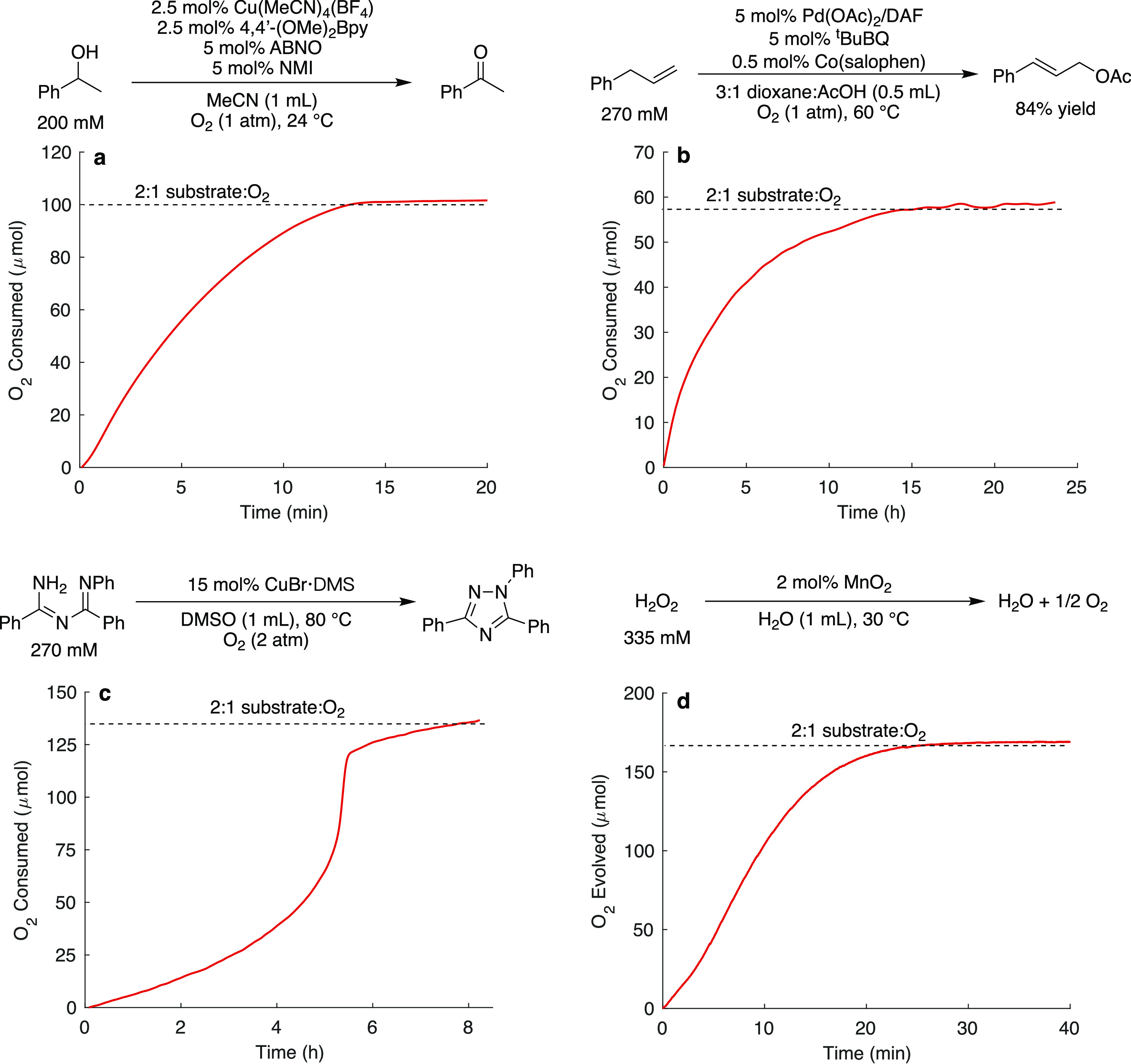
The versatility and sensitivity of the pressure-monitoring reactor are illustrated with four aerobic reactions that are the focus of attention in our lab: copper-catalyzed alcohol oxidation,17 palladium-catalyzed allylic acetoxylation,18 copper-catalyzed N–N bond formation,19 and MnO2-catalyzed hydrogen peroxide disproportionation (Fig. 3). Full experimental protocols are provided in the supplementary material, with the gas uptake/evolution data summarized below. Note that a blast shield or shatter resistant enclosure should be used for any pressurized reactions.
FIG. 3.

Gas uptake data obtained for different aerobic transformations using the reactor including Cu and nitroxyl catalyzed alcohol oxidation (a), Pd-catalyzed allylic acetoxylation (b), a Cu-catalyzed intramolecular N–N bond formation reaction (c), and a MnO2-catalyzed H2O2 disproportionation reaction (d). The data shown in (c) are adapted from Chem. Sci. 11, 1170 (2020); licensed under a Creative Commons Attribution (CC BY-NC) license.
The alcohol oxidation reaction was initiated by injection of the catalytic components through the sampling port into a mixture of the solvent and alcohol substrate within the reaction tube, filled with an initial pressure of 15 PSIa O2. The reaction proceeded to completion in 15 min, and the pressure was recorded every second [Fig. 3(a)]. We monitored a palladium-catalyzed allylic acetoxylation reaction to demonstrate the temperature-control the reactor can provide over a longer reaction time (25 h). The reaction was initiated by injection of the substrate into a pre-heated reaction solution at 60 °C under 15 PSIa O2, and the pressure was recorded every second [Fig. 3(b); >8 × 10⁴ total data points recorded]. With a set temperature of 60 °C, the reactor maintained an average temperature of 59.92 ± 0.04 °C throughout the time course (see Fig. S18 of the supplementary material). These data demonstrate the ability to collect a large amount of data while simultaneously maintaining strict temperature control. We conducted an N–N bond formation reaction starting at 2 atm O2 [Fig. 3(c)] to demonstrate how these high-resolution measurements can provide impactful kinetic information. The substrate inhibition of this reaction is apparent by the unusual gas uptake time course shown in Fig. 3(c), which reveals an acceleration in the rate as the substrate is consumed. Finally, we conducted a gas evolution reaction by the MnO2-catalyzed disproportionation of H2O2 [Fig. 3(d)]. The data demonstrate a continuous monitoring of the evolution of molecular oxygen from the reaction.
III. SUMMARY
We have developed a sensitive, multi-well, pressure-monitoring reactor. The monolithic stainless steel body attaches via a simple hand-tightened ring clamp to a disposable thick-walled microwave tube. The low headspace volume and high transducer sensitivity allow the user to monitor gas–liquid chemical reactions with good resolution. The multi-well block design allows experimenters to collect high-resolution, continuous time-course data for up to ten simultaneous experiments over time scales ranging from minutes to days. The good temperature control prevents undesirable pressure fluctuations that can complicate kinetic data analysis. Safety features include pressure relief valves, low voltage transducers to minimize spark-ignition potential, and thermal fuses to prevent runaway heating. The commercially available electronic hardware and the user-friendly open source software provide an accessible and customizable system for an array of users investigating chemical reactions that consume or generate relatively small quantities of gas during the reaction.
SUPPLEMENTARY MATERIAL
See the supplementary material for (1) general considerations, (2) the reactor cell design, (3) the heating block design, (4) the gas manifold design, (5) electronics—hardware, (6) electronics—software, and (7) experimental procedures.
AUTHORS’ CONTRIBUTIONS
C.A.S. and B.J.T. contributed equally to this work.
ACKNOWLEDGMENTS
We thank the NSF CCI Center for Selective C–H Functionalization (Grant No. CHE-1205646) for providing financial support to construct and test this reactor. Experimental studies used to demonstrate the reactor shown in Fig. 3 were funded by the NIH [Grant No. R35 GM134929, Fig. 3(a)], the NSF [Grant No. CHE-1953926, Fig. 3(b)], and the DOE [Grant No. DEFG02-05ER15690; Office of Science, Basic Energy Sciences, Fig. 3(c)]. Additional support was provided by the National Science Foundation Graduate Research Fellowship Program under Grant No. DGE-1747503 (C.A.S.). We would additionally like to thank Matthew Martin, James Mallarkey, and Kendall Schneider for machining assistance. We thank Caitlin Kozack and Dr. Michael Ryan for assistance with the gas uptake data collection. We also appreciate valuable discussions with Professor Clark Landis.
DATA AVAILABILITY
The data that support the findings of this study are available within the article and its supplementary material or from the corresponding author upon reasonable request.
REFERENCES
- 1.Kim S., Loose F., Bezdek M. J., Wang X., and Chirik P. J., J. Am. Chem. Soc. 141, 17900 (2019). 10.1021/jacs.9b09540 [DOI] [PubMed] [Google Scholar]
- 2.Han Z., Qiu F., Eisenberg R., Holland P. L., and Krauss T. D., Science 338, 1321 (2012). 10.1126/science.1227775 [DOI] [PubMed] [Google Scholar]
- 3.Forster D., J. Chem. Soc., Dalton Trans. 1979, 1639. 10.1039/dt9790001639 [DOI] [Google Scholar]
- 4.Hue R. J., Cibuzar M. P., and Tonks I. A., ACS Catal. 4, 4223 (2014). 10.1021/cs501447d [DOI] [Google Scholar]
- 5.Diwan M., Hwang H. T., Al-Kukhun A., and Varma A., AIChE J. 57, 259 (2011). 10.1002/aic.12240 [DOI] [Google Scholar]
- 6.Steinhoff B. A., Fix S. R., and Stahl S. S., J. Am. Chem. Soc. 124, 766 (2002). 10.1021/ja016806w [DOI] [PubMed] [Google Scholar]
- 7.Dydio P., Detz R. J., de Bruin B., and Reek J. N. H., J. Am. Chem. Soc. 136, 8418 (2014). 10.1021/ja503033q [DOI] [PubMed] [Google Scholar]
- 8.Stahl S. S., Angew. Chem., Int. Ed. 43, 3400 (2004). 10.1002/anie.200300630 [DOI] [PubMed] [Google Scholar]
- 9.Wang D., Weinstein A. B., White P. B., and Stahl S. S., Chem. Rev. 118, 2636 (2017). 10.1021/acs.chemrev.7b00334 [DOI] [PubMed] [Google Scholar]
- 10.Kaeffer N., Liu H.-J., Lo H.-K., Fedorov A., and Copéret C., Chem. Sci. 9, 5366 (2018). 10.1039/c8sc01924j [DOI] [PMC free article] [PubMed] [Google Scholar]
- 11.Mannel D. S., King J., Preger Y., Ahmed M. S., Root T. W., and Stahl S. S., ACS Catal. 8, 1038 (2018). 10.1021/acscatal.7b02886 [DOI] [Google Scholar]
- 12.Weisenburger G. A., Barnhart R. W., and Steeno G. S., Org. Process Res. Dev. 12, 1299 (2008). 10.1021/op800194g [DOI] [Google Scholar]
- 13.Wang Y.-J., Li W.-T., and Jiao L., Asian J. Org. Chem. 7, 570 (2018). 10.1002/ajoc.201700406 [DOI] [Google Scholar]
- 14.Landis C. R. and Halpern J., J. Am. Chem. Soc. 109, 1746 (1987). 10.1021/ja00240a025 [DOI] [Google Scholar]
- 15.Slot T. K., Shiju N. R., and Rothenberg G., Angew. Chem., Int. Ed. 58, 17273 (2019). 10.1002/anie.201911005 [DOI] [PMC free article] [PubMed] [Google Scholar]
- 16.Kennedy M. B. and Lacher J. R., J. Chem. Educ. 46, 533 (1969). 10.1021/ed046p533 [DOI] [Google Scholar]
- 17.Steves J. E. and Stahl S. S., J. Am. Chem. Soc. 135, 15742 (2013). 10.1021/ja409241h [DOI] [PMC free article] [PubMed] [Google Scholar]
- 18.Kozack C. V., Sowin J. A., Jaworski J. N., Iosub A. V., Stahl S. S., ChemSusChem 12, 3003 (2019). 10.1002/cssc.201900727 [DOI] [PMC free article] [PubMed] [Google Scholar]
- 19.Ryan M. C., Kim Y. J., Gerken J. B., Wang F., Aristov M. M., Martinelli J. R., and Stahl S. S., Chem. Sci. 11, 1170 (2020). 10.1039/c9sc04305e [DOI] [PMC free article] [PubMed] [Google Scholar]
Associated Data
This section collects any data citations, data availability statements, or supplementary materials included in this article.
Supplementary Materials
See the supplementary material for (1) general considerations, (2) the reactor cell design, (3) the heating block design, (4) the gas manifold design, (5) electronics—hardware, (6) electronics—software, and (7) experimental procedures.
Data Availability Statement
The data that support the findings of this study are available within the article and its supplementary material or from the corresponding author upon reasonable request.


