

Abstract
This paper presents the development and experimental evaluation of an active steering hand-held robotic system for milling and curved drilling in minimally invasive orthopaedic interventions. The system comprises a cable-driven continuum dexterous manipulator (CDM), an actuation unit with a handpiece, and a flexible, rotary cutting tool. Compared to conventional rigid drills, the proposed system enhances dexterity and reach in confined spaces in surgery, while providing direct control to the surgeon with sufficient stability while cutting/milling hard tissue. Of note, for cases that require precise motion, the system is able to be mounted on a positioning robot for additional controllability. A proportional-derivative (PD) controller for regulating drive cable tension is proposed for the stable steering of the CDM during cutting operations. The robotic system is characterized and tested with various tool rotational speeds and cable tensions, demonstrating successful cutting of three-dimensional and curvilinear tool paths in simulated cancellous bone and bone phantom. Material removal rates (MRRs) of up to 571 mm3/s are achieved for stable cutting, demonstrating great improvement over previous related works.
Keywords: Medical Robots and Systems, Compliant Joints and Mechanisms
I. INTRODUCTION
PREVIOUS work involving continuum dexterous manipulators (CDMs) for orthopaedic minimally invasive surgery (MIS) have focused on the kinematic characterization and implementation of CDMs using fully robotic platforms, for use with both hard and soft tissues [1], [2], [3], [4]. Such systems are shown to be capable of sub-millimeter positional accuracy [3], [5], taking full advantage of the increased workspace reach and maneuverability inherent to CDMs [3], [6]. However, a fully robotic system may be bulky, consuming precious workspace in the operating room and occluding the view of patient-side assistants. Further, they inconvenience the surgical team with the associated preoperative preparations, such as robot-patient registration, needed to ensure safe use of the fully robotic system. These factors increase the total preoperative time and the overall cost of treatment, necessitating the development of more compact system.
We present an adaptive, robotic system for orthopaedic MIS, intended for hand-held surgeon use but with the capability to optionally mount to a rigid-link robot, for robot-assisted and autonomous operations, which allows the system to be adapted to the surgeon’s preferences. For procedures such as core decompression of the femoral head and spinal decompression, the expanded reach of the CDM would minimize the cutting of healthy tissues while allowing for enhanced removal of the affected bone. Creating a hand-held system can allow for rapid surgeon evaluation by giving a hands-on experience of both the increased dexterity of CDMs and the ease of integration into existing procedures. To our knowledge, no hand-held systems using a CDM for cutting bone have been previously developed. However, Fuad et al. have developed a hand-held robotic system using a jointed manipulator, 8 mm in outer diameter (OD), for total hip arthroplasty [7], but their system lacks the hyper-redundancy, workspace, and smaller size possible with CDMs. Not only does their system require an additional vision tracking system for operation, but also requires encoders to be installed at the joints of manipulator, which adds preoperative time and sterilization complications to the surgical workflow.
This paper focuses on the design, development, and evaluation of a hand-held device that is flexible enough to enhance reach in confined spaces, yet sufficiently stiff for debriding hard tissue. Our system is designed towards the primary actuation of an existing cable-driven CDM developed specifically for minimally invasive orthopaedic interventions, e.g. robot-assisted treatment of osteolysis [1], [2], [3], [8], with secondary actuation of a flexible, rotary cutting tool that passes through the instrument channel of the CDM. Towards this goal, we have developed a proportional-derivative (PD) controller for controlling drive cable tension of the CDM, evaluated the system’s performance thereafter, determined the optimal system parameters, and demonstrated potential use cases.
The main contributions of this paper are as follows: 1) the design of an active steering hand-held device for milling and curved drilling in minimally invasive orthopaedic interventions; 2) identification of optimal cutting parameters for a force-controlled CDM; and 3) investigation of the utility of the active steering hand-held device for minimally invasive orthopaedic surgeries.
II. Robotic System Components
The hand-held system comprises a CDM, a flexible cutting instrument (FCI), an actuation unit that holds and actuates the CDM and FCI, and a handpiece to manually operate the system.
A. Continuum Dexterous Manipulator
The CDM (Fig. 1), previously developed by our group, is a notched Nitinol tube with with a maximum OD of 6 mm and and inner diameter (ID) of 4 mm. The ID of the CDM serves as an instrument channel for passing through different flexible tools [8] as well as a pathway for cutting debris and irrigation to flow [1]. Two pairs of interconnected channels run through the bendable section on both sides of the CDM, allowing for drive cables to pass through and for embedding fiber Bragg grating (FBG) sensors [3], [11]. For actuation, a 0.3 mm OD lubricated, stainless-steel cable is passed through one of the channels and knotted at the tip of the CDM. Pulling of the cable results in planar bending of the CDM towards the side the cable is inserted in, while remaining stiff in the direction normal to the plane of bending. If a second cable is installed on the opposing side of the first cable to achieve a pull-pull configuration, the CDM becomes capable of bends with multiple inflection points [4], [12].
Fig. 1.

a) Continuum dexterous manipulator used for experiments, b) flexible cutting instrument developed for cutting of bone.
B. Flexible Cutting Instrument
Several designs for flexible cutting and debriding instruments have been developed previously, demonstrating successful debridement of soft tissues and cutting of Sawbone [1], [4]. However, these designs lacked proper axial and radial constraints, resulting in excessive tool vibrations not conducive to high material removal rates (MRRs). Fig. 1 shows an improved FCI designed for cutting hard tissues, implementing concepts from machine tool spindle design, where the rotating tool is both axially and radially constrained using bearings [13]. This allows for higher rotational speeds, decreased tool run-out, and decreased heat generation compared to previous instruments. The cutting head is a 5.95 mm (15/64”) diameter, 4-flute carbide ball end-mill with 30 degree helix angle (88805A26, McMaster-Carr), which has been shortened and ground down to have a shank diameter of 2 mm, resulting in an effective cutting volume of 222.7 mm3. 4-flute geometry was chosen over previous 2-flute designs as a higher number of flutes results in lower cutting forces for a constant tool rotational speed and feed rate [14]. A custom, polyacetal thrust bearing with 6 mm OD and a 4 mm OD by 2 mm ID ball-bearing (672HZZ, Misumi) are used to constrain the cutting head. A 3.5 mm OD flexible torque coil (Asahi Intec USA, Inc.) is used to connect the cutting head assembly to a 2 mm OD, rigid stainless steel tubular shaft. The torque coil is adhered to the cutting head assembly and rigid shaft using epoxy (8265S, J-B Weld) on the ID and OD surfaces. For installation, the FCI is inserted into the instrument channel of the CDM and locked into the collet chuck of the BLDC motor (Fig. 2). Furthermore, a polyacetal sleeve bearing (80F-0202, Misumi) with 2 mm ID is fixed inside the CDM, constraining the rigid shaft radially to reduce vibrations during tool rotation (Fig. 1).
Fig. 2.

a) Robotic system assembled in its hand-held configuration, with the CDM, FCI, and handpiece installed. DOF of the actuation unit are highlighted in blue and b) Hand-held system milling a Sawbone sample.
C. Actuation Unit
Previous designs [2], [3], although capable of high accuracy, were bulky and not suitable for hand-held applications. In this paper, a new version of the actuation unit, shown in Fig. 2, is developed concurrently with the FCI. The actuation unit retains all degrees of freedom (DOF) of the previous designs while being 40% smaller by rectangular bounding volume and weighing approximately 1.6 kg. A DC motor with spindle drive (RE16, GP16, Maxon Group) is used to pull the drive cable and a DC gearhead motor (RE16, GP16C, Maxon Group) is used to actuate the roll axis, which rotates the CDM’s plane of bending about the CDM’s central axis. A brushless DC (BLDC) motor (ECX SPEED 22, Maxon Group) is used to rotate the FCI at desired rotational velocities up to 6000 rotations per minute (RPM). The CDM is affixed to the chuck on the front of the actuation unit. Embedded in the chuck is a section of self-lubricating polytetrafluoroethylene (PTFE) tubing (5239K24, McMaster-Carr), through which the CDM drive cable slides and is attached to a bi-directional load cell (Model 31, Honeywell) to directly measure cable tension. The load cell connects to an external amplifier (060-6827-02, Honeywell) which interfaces with a custom-designed printed circuit board (PCB) for data acquisition (DAQ) and motor control. Below the tool motor is a custom aluminum adapter plate that allows for attachment to a handpiece or an end-effector of a robot arm (Fig. 2).
D. Handpiece
The handpiece is a custom-designed handle with a single trigger (Fig. 2), similar in form factor to existing surgical drills. Pulling the trigger allows for direct cable tension control of the CDM, where pulling the trigger harder results in a proportionally higher desired cable tension setpoint for the PD controller. A load cell with integral amplifier (FX293X, TE Connectivity) is placed in-line behind the trigger to sense trigger pull force and is connected to the custom PCB. The handpiece is designed such that it can be unscrewed from the actuation unit and replaced with one that has different input devices, allowing for higher degree or a more preferred scheme of manual control by the surgeon. For example, a handpiece with two triggers and a rotary knob can be implemented for manual control of cable tension, cutting instrument rotational velocity, and trigger input gain, respectively.
III. Methods
A. Controller Design
The method of force control over cable velocity control is chosen due to findings from previous studies, which recommend higher tool rotational speeds and larger applied forces for minimum temperature generation during drilling of bone to prevent thermal necrosis [8], [9]. Past work involving CDMs with identical actuation mechanics have shown that drive cable tension is positively correlated with reaction forces along the bend plane at the CDM tip [8]. As such, direct control of cable tension allows for indirect regulation of cutting forces. In order to control cable tension, we use a simple closed-loop control model with the desired (setpoint) cable tension as the system input and actual cable tension (feedback) as the system output (Fig. 3). The continuous transfer function for the actuation unit plant P(s) is then found using linear model estimation techniques. Using P(s), a PD controller can be tuned to ensure that an optimal response and stability are achieved.
Fig. 3.
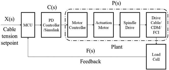
Block diagram of the control system showing input and output.
B. System Performance
Quantification of the system’s performance is done in the scope of surgical workflow integration. We investigate achievable volumetric MRRs and corresponding noise-to-signal ratios (NSRs) of the drive cable tension when milling and drilling simulated cancellous bone (Sawbone phantoms) to assess clinical relevance, as too slow of an MRR or too much vibration noise may render the system impractical for surgeon use. Sawbone phantoms (Pacific Research Laboratories, USA) are used for evaluation, since they offer uniform and consistent physical properties in the range of human bone [15]. MRR is calculated by:
| (1) |
where mr is the mass removed, tc is the total cutting time in seconds, and ρ is the sample density. In order to estimate the magnitude of vibrations during cutting, the NSR is used, defined by:
| (2) |
where fn is the nth element of the time-domain cable tension data and ffilt,n is the nth element of the filtered time-domain cable tension data.
We design cutting experiments based on the expected operations that take place in different orthopaedic surgeries, while replicating the core cutting motions involved. Examples of these surgeries include 1) osteolysis, in which less than 50% of lesions are removed during conventional procedures using rigid tools [10]; 2) core decompression of the femoral head, where sclerotic lesions must be removed; and 3) laminectomy, in which the lamina is cut while limiting damage to surrounding tissues. Specifically, we perform a parametric study to evaluate the effect of varying drive cable tension and tool rotational speed on MRR and NSR when milling, then we conduct drilling experiments to identify the system behavior for different cable tensions and feed velocities.
IV. Experiments
In order to determine the efficacy of the hand-held device as a value-adding tool for orthopaedic applications, we design our experiments to systematically evaluate the capabilities of the system.
A. Experimental Setup
To allow for repeatable and constrained testing of the system without the influence of a human operator, the robotic system, without the handpiece, is first mounted to a testbed (Fig. 4). The testbed consists of a rigid aluminum base, on which a custom 2-axis linear stage is attached. The first stage is motorized (RE16, GP16C, Maxon Group) and translates parallel to the central axis of the CDM to provide a controlled feed velocity for drilling experiments. The second stage is manually adjusted by a micrometer feed and translates perpendicularly to the first stage, allowing for adjustment of the starting position of Sawbone blocks relative to the CDM. Sawbone blocks are clamped to the top of the second stage using low-profile fixture clamps (84865A81, McMaster-Carr). In the last experiment, the system is removed from the testbed platform and the handpiece is installed to allow for unconstrained hand-held operation of the system (Fig. 2).
Fig. 4.

Experimental setup for the testbed configuration, with the CDM, FCI, and linear stage. The blue arrow represents the direction of the feed velocity while the green arrow represents the direction of micrometer feed.
A 32-bit microcontroller unit (MCU) (MKR Zero, Arduino) on the custom PCB is connected to a computer running the Simulink environment (R2020a, MathWorks), using the Simulink Support Package for Arduino Hardware for control algorithm deployment and DAQ at a frequency of 100 Hz. For the system characterization experiments, a separate DAQ device (myDAQ, National Instruments) is used to acquire cable tension data at a frequency of 1 KHz.
B. System Identification
Before cutting experiments are conducted, it should first be established that the system is controllable and responsive enough for surgeon use. To investigate this, a frequency response estimation test of the system is performed, using a closed-loop model that controls cable displacement velocity to achieve a desired cable tension setpoint. A 15 pounds per cubic foot (PCF) (240.2 kg/m3) Sawbone block is clamped onto the 2-axis linear stage and positioned so that contact is made with the cutting head and a CDM cable tension of 0.1 N is reached (Fig. 5). A series of sinusoidal waves of varying frequencies (sinestream signal), from 0.01 Hz - 40 Hz, 5 periods each, is used to command the setpoint cable tension from 0 - 15 N peak-to-peak. A maximum of 15 N is chosen as the CDM reaches a 90 degree bend angle at that cable tension. It should be noted that the CDM notch geometry can be modified to achieve a desired cable tension at a certain angle for a specific surgical application requirement. This setup simulates the contact forces of the system’s intended operating environment, but without any tool rotation. An initial PD controller:
| (3) |
with Kp = 540 and and Kd = 54 is chosen for feedback control, such that controller saturation is largely avoided. Cable tension and controller output data are collected continuously for the duration of the experiment.
Fig. 5.

a) Experimental setup for system identification and b) experimental setup for milling, showing the starting position of the CDM relative to the Sawbone sample.
C. System Characterization
The first half of these experiments seeks to characterize the effects of rotational tool velocities on cable tension across the CDM’s bending range. The CDM is bent to cable tensions in the range of 5 N to 15 N, in discrete 5 N intervals, using a tuned PD controller. At each bend interval, the flexible cutting instrument is rotated in the range of 1000 RPM to 6000 RPM in discrete 1000 RPM intervals, for a total of 24 trials. Cable tension data for each trial is collected for 5 seconds after steady-state RPM is achieved. The second half of these experiments seeks to characterize the effects of cable displacement velocity on cable tension with the cutting instrument installed. The CDM is bent to approximately 90 degrees at constant cable displacement velocities of 0.1 mm/s, 0.2 mm/s, 0.4 mm/s, 0.5 mm/s, 1 mm/s and 2 mm/s, for a total of 6 trials. Cable tension data for each trial is collected for the duration of the CDM bending.
D. Milling Experiments
In the first part of these experiments, a tuned PD controller is used to control cable tension during milling of Sawbone blocks, in which the CDM is bent such that the cutting head performs a sweeping motion. The plane of bending is set parallel to the top surface of the linear stage. Before milling, each Sawbone samples is processed with a milling machine to remove a circular section of 31.15 mm radius (Fig. 5) to allow for clearance of the CDM body to allow for longer milling times. The mass of each sample is then recorded with a precision balance (1601, Sartorius). The CDM is pre-tensioned to 0.5 N, and the Sawbone sample is clamped onto the top of the linear stage and positioned so that the cutting head starts at full axial depth of cut (DOC), as shown in Fig. 5. A rotational velocity is applied to the cutting instrument and the linear stage is adjusted such that incidental contact is made between the cutting head and Sawbone sample. A specified cable tension setpoint is then commanded to the PD controller so that the CDM begins cutting. The CDM is stopped before it reaches its obstacle-free bend angle for the specified cable tension setpoint, so that the total cutting time of the trial can be accurately measured. The Sawbone sample is removed from the linear stage and measured on the balance to determine the total mass removed by milling. These experiments are run using 5 PCF (80.09 kg/mm3) and 10 PCF (160.18 kg/mm3) Sawbone blocks, with 10 N and 15 N cable tension setpoints, and with 2000, 4000, and 6000 RPM rotational speeds for a total of 12 trials. Cable tension data, cutting time, and removed mass data are collected for each trial.
The second part of these experiments uses a constant cable displacement velocity for milling, in order to have a benchmark for comparison of system NSR for the different methods of control. These experiments are run using 10 PCF Sawbone blocks, fixtured in the same manner as before, with 0.1 mm/s and 0.2 mm/s velocities, and with 2000 RPM to 6000 RPM rotational speeds in 1000 RPM increments, for a total of 10 trials. The cable displacement velocities are chosen based on similar velocities used in [4].
E. Curved Drilling Experiments
For these experiments, the tuned PD controller is used to control cable tension during curved drilling through Sawbone blocks, with the plane of bending kept the same as the milling experiments. Before drilling, Sawbone samples are pre-drilled with an 8 mm drill to a depth of 9 mm to allow for consistent entry of the cutting head, then measured for mass on the precision balance. A sample is then clamped onto the linear stage and the CDM is inserted into the hole until incidental contact is made with the cutting head (Fig. 6). Concurrently, a 2000 RPM rotational velocity is applied to the cutting instrument, the PD controller is commanded to a specified setpoint, and the motorized stage is commanded to a constant feed velocity. In this manner, curvilinear drilling is achieved by a combination of the sample velocity from the linear stage and the bending motion from the CDM. The CDM and motorized stage are stopped when the base of the Sawbone samples reaches within 15 mm of the end of the CDM’s bendable section. These experiments are run using 5 PCF and 10 PCF Sawbone blocks, with 2.5 and 5 N cable tension setpoints, 0.2 mm/s and 0.4 mm/s feed velocities, and with 2000 RPM rotational speed for a total of 8 trials. Cable tension data, cutting time, and removed mass data are collected for each trial.
Fig. 6.

a) Experimental setup for testbed curved drilling and b) experimental setup for hand-held curved drilling, simulating core decompression of the femoral head.
F. Hand-held Experiments
In this set of experiments, hand-held use cases are investigated to assess clinical relevance. Hand-held milling and curved drilling are performed on 5 PCF Sawbone blocks to demonstrate the ease of hand-held control and the timescale of use compared to previous works. Curved drilling is performed on a Sawbone femur phantom to demonstrate a potential solution for MIS core decompression of the femoral head, as softer tissues are not involved. A portion of phantom has been cut away for better visualization and for clearance of the actuation unit chuck (Fig. 6). It should be noted that the length of the rigid section of the CDM can be adjusted during fabrication to meet application requirements. Lastly, an additional drive cable is attached to CDM, and is used to demonstrate the poses possible with S-shape bending, to show applicability to procedures such as posterior cruciate ligament (PCL) reconstruction that deal with navigation through soft tissue.
V. Results and Discussion
A. System Identification and Controller Tuning
Fig. 7-a shows the resulting system response for the system identification experiment. Tracking between the cable tension and setpoint command is shown to diverge as the sinestream frequency increases, with a concurrent increase in controller output amplitude. Since no instabilities or outliers are encountered, the cable tension and control output data are passed to the ssest function in MATLAB, which computes the best-fit state-space model for the system plant (Fig. 3). A 2nd-order model is found, with 0.31% normalized RMS error (NRMSE), or a 99.69% fit to the estimation data, when evaluated against the original time-domain data using the prediction focus loss function in ssest. The state-space plant model is converted to a continuous transfer function using the tf function, and is found to be:
| (4) |
which is stable, with poles p1 = −11.2084 and p2 = −0.0135. The PID Tuner application in Simulink is used with (4) to tune a PD controller for robust transient behavior with a fast response time, resulting in:
| (5) |
where Kp = 1800, Kd = 280, N = 15, and a 1.3% error deadband are found to be optimal after slight manual tuning. The optimized PD controller is then validated against the simulated step response (Fig. 7-b), and shows adequate tracking for both the cable tension and controller output. The rise time of the system is found to be 0.9784 s, which suggests that the system is able to react fast enough to accommodate steady surgeon manipulation.
Fig. 7.

a) Time-domain system response to sinestream cable tension setpoint with untuned PD controller. b) Step response of the system with a tuned PD controller, comparing experimental and simulated results. c) Cable tension variability data for different cable tension setpoints and FCI rotational velocities. Points represent the average cable tension for each trial, and error bars represent the variability of the time-domain data. d) Time-domain cable tension data for bending of the CDM with different cable displacement velocities.
B. System Characterization
Regardless of FCI rotational velocity, the PD controller maintains an average cable tension equal to the commanded setpoint (Fig. 7-c). We can observe that as RPM increases, the range of cable tension error increases, with a positive bias. Also, there exists a positive correlation between cable tension setpoint and error range. Such behavior suggests that there may be harmonic oscillations with amplitude proportional to FCI rotational velocity. The mean tracking error and standard deviation are found to be 0.0015 N and 0.4105 N, respectively.
Bending of the CDM with the FCI installed results in a linear trend between cable tension and time, regardless of cable displacement velocity (Fig. 7-d). However, local instances of slip can be observed, where cable tension momentarily decreases then resumes increasing. This occurs periodically and at consistent cable tensions for all trials, indicating that there may be regions of higher friction in the CDM channel-drive cable interaction. Overall, the general behavior and magnitude of variability (noise) supports the method of system estimation using a linear control approach.
C. Milling Experiments
Fig. 8-a shows the achieved MRRs for the milling experiments using the tuned PD controller. MRR is calculated assuming that the Sawbone samples are isotropic, with constant density. The results indicate that higher MRRs are achieved with larger cable tensions, while MRR decreases with increasing Sawbone density. MRR is negatively correlated with RPM for trials using a 15 N setpoint, while MRR increases after 4000 RPM for trials using a 10 N setpoint. Fig. 8-b shows the time-domain cable tension data for the trials with 10 PCF Sawbone samples. It can be seen that the 6000 RPM, 10 N trial experiences significant vibrations near the last 2 seconds of cutting, which can explain the associated increase in MRR. While higher MRRs are desired, the causal vibrations negate any derived benefit due to the increased positional uncertainty of the CDM. The same behavior was also found in the 5 PCF experiments. A finite impulse response low-pass filter (LPF) with 1 Hz cutoff frequency is applied to the time-domain cable tension data. Fig. 8-c shows the calculated NSR for the milling experiments using PD cable tension control and cable displacement velocity control. For velocity control trials, we can observe that NSR rises significantly faster than that of the PD control trials, resulting in a 145.6% greater average NSR when compared to the 10 PCF, PD-controlled trials at 6000 RPM. This suggests that cutting bone too slowly with too high of an RPM will induce more vibrations in the CDM. Similar in effect to the MRR results, NSR is positively correlated with RPM, with higher cable tension setpoints resulting in a slower rate of increase. This supports the MRR findings, as the vibrational displacements during cutting reduces the average cutter feed-rate and consequently reduces MRR. From these experiments, we determine that the optimal FCI rotational velocity for this system is 2000 RPM and that higher cable tensions are more beneficial for cutting performance. For the 2000 RPM trials using PD control, the mean and standard deviation of the NSR are 0.019 and 0.004, respectively.
Fig. 8.

a) Material removal rate for each combination of FCI rotational velocity, Sawbone density, and cable tension setpoint using a PD controller for milling. b) Time-domain cable tension data (unfiltered) for milling of 10 PCF Sawbone using a PD controller. c) Noise-to-signal ratio for each combination of FCI rotational velocity, Sawbone density, and cable tension setpoint for both PD control and velocity control milling experiments.
While previous works from our group have implemented various forms of control for the CDM, including proportional cable tension control [4] and cable velocity control [3], to test cutter performance, these experiments were performed in the scope of fully-robotic control, using cutting feed rates impractical for hand-held surgeon use. In the case of [3], a mean MRR of 0.0083 mm3/s was reported with 10 and 15 PCF Sawbone. For our newly developed system, a maximum MRR of 208 mm3/s is achieved with 10 PCF Sawbone. An improvement of this magnitude allows for significantly decreased operating times and improved surgeon operability.
In order to estimate cutting tool temperature, the 10 PCF, 0.1 mm/s, and 6000 RPM trial was repeated, but with a type K thermocouple affixed to the distal end of the CDM. This trial was chosen to represent the extreme bounds of the system’s operating range. A maximum of 72 °C was reached during a cutting period of 50 seconds, which indicates that the temperature at the bone-cutting interface remains low enough to be cooled by irrigation to avoid thermal necrosis of the bone [9]. As irrigation is freely available in the operating theater, the system does not negatively impact existing surgical workflows from a heat generation perspective.
D. Curved Drilling Experiments
Table 1 shows the performance results of the curved drilling experiments. Following the trend of the milling experiments, the results indicate that use of a higher cable tension for drilling results in decreased noise, in which a 57% mean decrease in NSR is found when comparing 2.5 N and 5 N trials. For these experiments, the mean and standard deviation of the NSR are 0.019 and 0.010, respectively, which mirror those of the milling trials using PD control in the previous section. As drilling involves stabilization of the cutter around its entire circumference due to the surrounding material, e.g bone or soft tissue, these NSR values are expected. From these results, we can infer that the system is appropriate stabilized for both drilling and milling when using PD control and an FCI rotational velocity of 2000 RPM.
TABLE I.
MRR and NSR for Curved Drilling Experiments
| Density (PCF) |
Cable Tension (N) |
Feed Velocity (mm/s) |
MRR (mm^3/s) |
NSR |
|---|---|---|---|---|
| 5 | 2.5 | 0.2 | 7.91 | 0.022 |
| 0.4 | 15.71 | 0.027 | ||
| 5 | 0.2 | 9.59 | 0.012 | |
| 0.4 | 19.87 | 0.016 | ||
| 10 | 2.5 | 0.2 | 5.83 | 0.037 |
| 0.4 | 9.61 | 0.021 | ||
| 5 | 0.2 | 4.65 | 0.006 | |
| 0.4 | 9.18 | 0.009 |
The maximum MRRs achieved in these experiments is 19.87 mm3. Increasing cable tension setpoint from 2.5 N to 5N resulted in a 24% mean increase in MRR for 5 PCF Sawbone trials, but a 12% mean decrease in MRR for the 10 PCF Sawbone trials. The cause of this behavior can be observed in the cross-sectioned Sawbone samples (Fig. 9), where the trajectories cut in the 5 PCF, 5 N setpoint samples have a distinctly smaller radius of curvature compared to those cut in the 10 PCF, 5 N setpoint samples. As the FCI cutting head and CDM body are nearly identical in diameter, the difference in trajectory curvature between the 5 PCF and 10 PCF samples indicates that while drilling through the softer 5 PCF Sawbone, the contact forces along the CDM body are enough to deform the surrounding material to allow for the cutting head to engage the material axially and radially. However, with the harder 10 PCF Sawbone, the contact forces are insufficient to deform the surrounding material enough, causing the cutting head to only cut axially, which reduces its effective cutting volume. This can be solved by using a higher maximum cable tension setpoint, starting with a slow ramp-up upon insertion of the cutting head into the pre-drilled entry point, or by using a cutting head with a diameter larger than the CDM body.
Fig. 9.

Cross-sectional view of the drilling experiment samples.
E. Hand-held Experiments
All of the hand-held demonstrations were executed successfully. The 5 PCF Sawbone blocks were milled and drilled without any visible signs of instability or chatter, as shown in Fig. 10-a and -b. Similarly, curvilinear drilling through the femur phantom was also successful (Fig. 10-d). It should be noted that if a CDM with a longer rigid section was used, a smaller radius of curvature for the drilling trajectory would have been possible. Fig. 11 shows the LPF time-domain cable tension data for the hand-held cutting experiments, in which adequate tracking between the cable tension setpoint and the actual cable tension is observed. NSR for the block milling, block drilling, and phantom drilling experiments were found to be 0.260, 0.150, and 0.178, respectively, which is acceptable when considering the variation in the setpoint command. As shown in Fig. 11, for the drilling experiments, sharp increases in cable tension, of approximately 5 N magnitude, are experienced during rapid retraction of the CDM from the drilled holes. Such behavior occurs due to the trigger being released, thus commanding the setpoint to 0 N, while the CDM is still inside the sample. This can be solved by using a bi-directional input device, such as a joy stick, for steering the CDM using incremental setpoint changes. As conventional orthopaedic surgeries often rely on computed tomography (CT)-guided freehand motion with surgical drills, these results demonstrate the viability of the hand-held system for cutting bone while relying solely on the surgeon’s audiovisual and haptic feedback, allowing for easier integration into existing surgical workflows.
Fig. 10.

Demonstrations from the hand-held experiments, consisting of a a) overhead view of the block milling result, b) cross-sectional view of the block drilling result, c) overhead view of the block drilling trial, d) cross-sectional view of the femur phantom result, e) piecewise bending with two drive cables, and f) S-shape bending with two drive cables.
Fig. 11.

Time-domain cable tension data (filtered) for the hand-held cutting experiments.
By attaching a second drive cable in one of the notches halfway through the bendable section of the CDM, two additional modes of bending are achieved (Fig. 10-c, -e), where applying relatively equal amounts of cable tension on both cables results in an S-shape bend and applying cable tensions with heavy bias towards one side results in a piecewise-like straight, then bent pose. Use of both cables can increase the axial stiffness of the CDM, decreasing buckling and allowing for increased drilling feed rates. Clinically, such bends would remove the need to drill from multiple entry points in the case of PCL reconstruction or would reduce the total trajectory length in the case of core decompression, due to the sharper angles possible with the piecewise-like bend.
VI. Conclusion
We have developed an active steering hand-held robotic system for milling and curved drilling in MIS orthopaedic surgery that demonstrates clinical relevance to a multitude of procedures. To fully take advantage of the capabilities offered by CDMs, additional controller types, such as input shaping and impedance control, and input control schemes will be investigated in future work to minimize surgical risk and reduce operating times. We also seek to explore the potential of augmented-reality system monitoring and the incorporation of a temperature sensor in the CDM, with validation from cadaveric trials.
Supplementary Material
Acknowledgments
This paper was recommended for publication by Editor Pietro Valdastri upon evaluation of the Associate Editor and Reviewers’ comments. This work was supported by NIH grant 2R01EB016703 and in part by a collaborative research agreement with the Multi-Scale Medical Robotics Center in Hong Kong.
References
- [1].Alambeigi F, Sefati S, Murphy RJ, Iordachita I and Armand M, ”Design and characterization of a debriding tool in robot-assisted treatment of osteolysis,” 2016 IEEE International Conference on Robotics and Automation (ICRA), Stockholm, 2016, pp. 5664–5669, doi: 10.1109/ICRA.2016.7487787. [DOI] [Google Scholar]
- [2].Murphy RJ, Kutzer MDM, Segreti SM, Lucas BC, and Armand M, ”Design and kinematic characterization of a surgical manipulator with a focus on treating osteolysis,” Robotica, vol. 32, no. 6, pp. 835–850, 2014. doi: 10.1017/S0263574713001082 [DOI] [Google Scholar]
- [3].Sefati S et al. , ”A Surgical Robotic System for Treatment of Pelvic Osteolysis Using an FBG-Equipped Continuum Manipulator and Flexible Instruments,” in IEEE/ASME Transactions on Mechatronics, doi: 10.1109/TMECH.2020.3020504. [DOI] [PMC free article] [PubMed] [Google Scholar]
- [4].Alambeigi F et al. , ”A Curved-Drilling Approach in Core Decompression of the Femoral Head Osteonecrosis Using a Continuum Manipulator,” in IEEE Robotics and Automation Letters, vol. 2, no. 3, pp. 1480–1487, July 2017, doi: 10.1109/LRA.2017.2668469. [DOI] [Google Scholar]
- [5].Sefati S, Gao C, Iordachita I, Taylor RH, Armand M and Armand M, ”Data-Driven Shape Sensing of a Surgical Continuum Manipulator Using an Uncalibrated Fiber Bragg Grating Sensor,” in IEEE Sensors Journal, doi: 10.1109/JSEN.2020.3028208. [DOI] [PMC free article] [PubMed] [Google Scholar]
- [6].Alambeigi F, Sefati S and Armand M, ”A Convex Optimization Framework for Constrained Concurrent Motion Control of a Hybrid Redundant Surgical System,” 2018 Annual American Control Conference (ACC), Milwaukee, WI, 2018, pp. 1158–1165, doi: 10.23919/ACC.2018.8430983. [DOI] [Google Scholar]
- [7].Fuad ANBA, Elangovan H, Deep K and Yao W, ”A Robotic Flexible Drill and Its Navigation System for Total Hip Arthroplasty,” Ann Biomed Eng. 2018. March;46(3):464–474. doi: 10.1007/s10439-017-1959-5. Epub 2017 Nov 22. PMID: 29168018; PMCID: PMC5809567. [DOI] [PMC free article] [PubMed] [Google Scholar]
- [8].Kutzer MDM, Segreti SM, Brown CY, Armand M, Taylor RH and Mears SC, ”Design of a new cable-driven manipulator with a large open lumen: Preliminary applications in the minimally-invasive removal of osteolysis,” 2011 IEEE International Conference on Robotics and Automation, Shanghai, 2011, pp. 2913–2920, doi: 10.1109/ICRA.2011.5980285. [DOI] [Google Scholar]
- [9].Pandey RK and Panda SS, ”Drilling of bone: A comprehensive review,” J Clin Orthop Trauma. 2013. March;4(1):15–30. doi: 10.1016/j.jcot.2013.01.002. Epub 2013 Jan 18. PMID: 26403771; PMCID: PMC3880511. [DOI] [PMC free article] [PubMed] [Google Scholar]
- [10].Engh CA Jr, Egawa H, Beykirch SE , Hopper RH Jr and Engh CA, ”The quality of osteolysis grafting with cementless acetabular component retention,” Clin Orthop Relat Res. 2007. December;465:150–4. doi: 10.1097/BLO.0b013e3181576097. PMID: 17876287. [DOI] [PubMed] [Google Scholar]
- [11].Sefati S, Alambeigi F, Iordachita I, Taylor RH and Armand M, ”On the effect of vibration on shape sensing of continuum manipulators using fiber Bragg gratings,” 2018 International Symposium on Medical Robotics (ISMR), Atlanta, GA, 2018, pp. 1–6, doi: 10.1109/ISMR.2018.8333303. [DOI] [Google Scholar]
- [12].Segreti SM, Kutzer MDM, Murphy RJ and Armand M, ”Cable length estimation for a compliant surgical manipulator,” 2012 IEEE International Conference on Robotics and Automation, Saint Paul, MN, 2012, pp. 701–708, doi: 10.1109/ICRA.2012.6225069. [DOI] [Google Scholar]
- [13].Abele E, Altintas Y and Brecher C, ”Machine tool spindle units,” CIRP Annals,Volume 59, Issue 2, 2010, 781–802, ISSN 0007-8506, 10.1016/j.cirp.2010.05.002. [DOI] [Google Scholar]
- [14].Rubeo MA and Schmitz TL, ”Milling Force Modeling: A Comparison of Two Approaches, Procedia Manufacturing, Volume 5, 2016, 90–105, ISSN 2351-9789, 10.1016/j.promfg.2016.08.010. [DOI] [Google Scholar]
- [15].Shim V, Boheme J, Josten C and Anderson I, (August 29th 2012). ”Use of Polyurethane Foam in Orthopaedic Biomechanical Experimentation and Simulation,” IntechOpen, 2012, DOI: 10.5772/47953 [DOI] [Google Scholar]
Associated Data
This section collects any data citations, data availability statements, or supplementary materials included in this article.