Abstract
Three-dimensional (3D) printing of biodegradable polymers has rapidly become a popular approach to create scaffolds for tissue engineering. This technique enables fabrication of complex architectures and layer-by-layer spatial control of multiple components with high resolution. The resulting scaffolds can also present distinct chemical groups or bioactive cues on the surface to guide cell behavior. However, surface functionalization often includes one or more post-fabrication processing steps, which typically produce biomaterials with homogeneously distributed chemistries that fail to mimic the biochemical organization found in native tissues. As an alternative, our laboratory developed a novel method that combines solvent-cast 3D printing with peptide-polymer conjugates to spatially present multiple biochemical cues in a single scaffold without requiring post-fabrication modification. Here, we describe a detailed, stepwise protocol to fabricate peptide-functionalized scaffolds and characterize their physical architecture and biochemical spatial organization. We used these 3D-printed scaffolds to direct human mesenchymal stem cell differentiation and osteochondral tissue formation by controlling the spatial presentation of cartilage-promoting and bone-promoting peptides. This protocol also describes how to seed scaffolds and evaluate matrix deposition driven by peptide organization.
Keywords: scaffold, 3D printing, spatial organization, osteochondral
BACKGROUND
Osteochondral (OC) tissue is composed of hyaline cartilage, calcified cartilage, and subchondral bone. Each region plays a distinct role in distributing mechanical forces during loading for normal joint function [1]. Functional repair of OC tissue remains a challenge because the transition from bone to cartilage contains gradients in biochemical and physical properties [2]. Regenerating this complex tissue requires engineering an organized microenvironment that will direct cells to restore the entire integrated tissue unit.
A popular strategy in tissue engineering is the use of biodegradable polymer-based scaffolds to guide tissue regeneration [3]. Scaffold materials can be functionalized with various chemical groups or bioactive cues to drive stem cell differentiation and encourage secretion of tissue-specific extracellular matrix (ECM) [4,5]. However, techniques for surface functionalization often include one or more post-fabrication steps. For example, scaffold surfaces can be chemically modified via aminolysis [6], hydrolysis [7], or chemical grafting [8] to generate functional groups for covalently linking biomolecules. This process can lead to undesirable changes to scaffold topography and morphology [9,10] and often produces biomaterials with homogeneously distributed chemistries that fail to mimic the spatial biochemical gradients found in native tissues.
Developing fabrication methods to create materials with biologically-relevant, complex, and dynamic gradients has become increasingly important for the tissue engineering field [11]. State-of-the-art strategies include electrospinning, microfluidics, 3D printing, component redistribution, and controlled phase changes [11-13]. Our lab has developed a novel method to spatially present different functional groups in a single, continuous scaffold by solvent-cast 3D printing with peptide-polymer conjugates [14]. Chemistries become displayed on the surface during fabrication without the need for post-functionalization steps. This technique thus enables fabrication of diverse and complex architectures as well as spatial presentation of different biochemical cues via layer-by-layer deposition, expanding our ability to fine-tune cell-material interactions. For example, we found that spatially presenting different peptide sequences within the same scaffold significantly affected local cell response [14]. Here, we describe a detailed and stepwise procedure to fabricate and characterize spatially organized constructs for OC tissue engineering as well as how to evaluate zonal tissue formation in response to peptide organization. This platform can be adapted for other applications by tailoring peptide sequences and scaffold architecture to a specific tissue of interest.
MATERIALS
Safety Data Sheets (SDS) for all chemicals and reagents must be reviewed before starting. Additional precautions should be taken when handling chemicals indicated with an asterisk (*).
Peptide-polymer conjugates
Reagents
✓ Peptides: Each peptide sequence must include a cysteine on the N- or C-terminus. Cysteine contains a thiol group necessary to conjugate the peptide to the maleimide-modified polymer via Michael addition. The sequence should also include a glycine spacer between the cysteine and sequence of interest to enhance presentation on the scaffold surface. In addition, the peptide can be modified with a bioorthogonal group (i.e., biotin, azide) to selectively tag the peptide with a fluorophore after printing to visualize its location and concentration.
✓ Poly(ε-caprolactone) (PCL), Molecular Weight 14 kDa (Sigma-Aldrich, USA, Cat. # 440752)
✓ p-Maleimidophenyl isocyanate (PMPI) (Chem-Impex, USA, Cat. # 23067)
✓ *N-methyl-2-pyrrolidone (NMP), anhydrous (VWR, USA, Cat. # AA43741-5Y)
✓ *Diethyl ether (DEE) (VWR, USA, Cat. # BDH1121)
✓ Ultrapure water (reverse osmosis water purified using PURELAB flex 2, ELGA, UK)
✓ *Dichloromethane-d2 (DCM-d2) (Sigma-Aldrich, USA, Cat. # 444324)
✓ *Dimethyl sulfoxide-d6 (DMSO)-d6 (VWR, USA, Cat. # EM1.03562.0009)
Equipment
✓ Sonicator (Branson Ultrasonics Corporation, USA, model: M2800H)
✓ Vortex mixer (VWR, USA, Cat. # 10153-838)
✓ Magnetic stirring plate (VWR, USA, Cat. # 97042-642)
✓ Centrifuge (ThermoFisher Scientific, Germany, model: Sorvall Legend X1R)
✓ Glass filtering flask, 500 ml with side arm (VWR, USA, Cat. # 89000-384)
✓ Glass filtration Buchner funnel, 60 ml, fritted, G3 medium porosity (VWR, USA, Cat. # 89426-732)
✓ Disposable dust-free wipes (Kimwipe) (VWR, USA, Cat. # 470173-504)
✓ Nuclear magnetic resonance (NMR) (400 MHz, Bruker, USA)
✓ NMR tubes and caps (VWR, USA, Cat. # 82005-324)
Peptide-PCL inks
Reagents
✓ Peptide-PCL conjugate synthesized in step 1 in the Protocol section
✓ Poly(ε-caprolactone) (PCL), Molecular Weight 80 kDa (Polysciences, USA, Cat. # 26290)
✓ *1,1,1,3,3,3-Hexafluoro-2-propanol (HFIP) (VWR, USA, Cat. # 101775-234)
Equipment
✓ Vortex mixer (VWR, USA, Cat. # 10153-838)
✓ Wrist-action shaker (Burrell Scientific, USA, model: 75)
✓ Centrifuge tubes, 50 ml (conicals) (VWR, USA, Cat. # 89401-562)
✓ Luer-lock syringes, 10 ml (VWR, USA, Cat. # 53548-023)
✓ Printer syringes (Nordson EFD, USA, Cat. # 7012072)
✓ End caps (Nordson EFD, USA, Cat. # 7012190)
✓ Tip caps (Nordson EFD, USA, Cat. # 7012198)
✓ Syringe plungers (Nordson EFD, USA, Cat. # 7012168)
✓ Glass syringe, 1000 μl accuracy (Hamilton Co, USA, Cat. # 81320)
✓ Glass syringe, 100 μl accuracy (Hamilton Co, USA, Cat. # 81020)
✓ Parafilm (VWR, USA, Cat. # 52858-032)
Solvent-cast 3D-printed scaffolds
Reagents
✓ Peptide-PCL inks created in step 2 in the Protocol section
Equipment
✓ 3D printer (Nordson EFD, USA)
✓ Disposable dust-free wipes (Kimwipe) (VWR, USA, Cat. # 470173-504)
✓ Double-sided adhesive tape (3M, USA)
✓ Feeler gauge (McMaster-Carr, 0.1 mm: Cat. # 2300A7, 0.15 mm: Cat. # 2300A8, or 0.2 mm: Cat. # 2300A)
✓ Water-soluble hairspray (Got2b Glam Force Hairspray)
✓ Needle (Nordson EFD, USA, 27 G: Cat. # 7018395, 30 G: Cat. # 7018424, or 32 G Cat. # 7018462)
Scaffold morphology
Reagents
✓ Solvent-cast 3D-printed scaffolds created in step 3 in the Protocol section
Equipment
✓ Scanning electron microscope (SEM) (LEO 1550 Zeiss, USA)
✓ Sputter coater (Electron Microscopy Sciences, USA)
✓ Polytetrafluoroethylene (PTFE)-coated razor (Electron Microscopy Sciences, USA, Cat. # 71970)
✓ SEM stub (Electron Microscopy Sciences, USA, Cat. # 75120)
✓ Double-sided carbon tape (Electron Microscopy Sciences, USA, Cat. # 77816)
Peptide presentation
Reagents
✓ Solvent-cast 3D-printed scaffolds created in step 3 in the Protocol section
✓ Ultrapure water (reverse osmosis water purified using PURELAB flex 2, ELGA, UK)
✓ Phosphate buffered saline (PBS) (VWR, USA, Cat. # 97062-730)
✓ Bovine serum albumin (BSA) (Sigma-Aldrich, USA, Cat. # A3803)
✓ TWEEN®20 (Sigma-Aldrich, USA, Cat. # P1379)
✓ Streptavidin-FITC (Sigma-Aldrich, USA, Cat. # S3762)
✓ Sodium azide (Sigma-Aldrich, USA, Cat. # 71290)
✓ Triton X-100 (Sigma-Aldrich, USA, Cat. # X100-500ML)
✓ Dibenzocyclooctyne-Cyanine3 (DBCO-Cy3) (Sigma-Aldrich, USA, Cat. # 777366)
✓ *Dimethyl sulfoxide (DMSO) (VWR, USA, Cat. # BDH1115)
✓ *Isopropyl alcohol (IPA) (VWR, USA, Cat. # BDH1133)
✓ Hyaluronate fluorescein (fl-HA) (MW 50K) (Creative PEGWorks, USA, Cat. # HA-807)
✓ *Ethanol (EtOH) (VWR, USA, Cat. # BDH1156)
✓ Cyanine3 amine (amino-Cy3) (BroadPharm, USA, Cat. # BP-22558)
✓ Pierce™ 20X borate buffer (ThermoFisher Scientific, USA, Cat. # 28341)
✓ N-Hydroxysuccinimide (NHS) (Sigma-Aldrich, USA, Cat. # 56480)
✓ 1-ethyl-3(3-dimethylaminopropyl)carbodiimide (EDC) (Sigma-Aldrich, USA, Cat. # 39391)
Equipment
✓ Rocker (VWR, USA, model: BR2000-GM)
✓ Confocal fluorescence microscope (C2+ laser scanning, Nikon, USA)
✓ 24-well standard multi-well cell culture plates (VWR, USA, Cat. # 10062-896)
✓ Disposable biopsy punches, 3mm diameter (Integra™ Miltex®, USA, Cat. # 33-32)
Scaffold seeding and cell culture
Reagents
✓ Solvent-cast 3D-printed scaffolds created in step 3 in the Protocol section
✓ Sylgard™ 184 Silicone Elastomer (VWR, USA, Cat. # 102092-312)
✓ *Ethanol (EtOH) (VWR, USA, Cat. # BDH1156)
✓ Reverse osmosis (RO) water
✓ Trypsin EDTA (ethylenediaminetetraacetic acid) 1X (Corning, USA, Cat. # 25-053-CI)
✓ Gibco™ Dulbecco’s Modified Eagle medium (DMEM), high glucose, GlutaMAX™ Supplement, pyruvate (Fisher Scientific, USA, Cat. # 10-569-044)
✓ Penicillin:Streptomycin:Amphotericin B solution (Antibiotic/antimycotic) (Corning, USA, Cat. # 30-004-CI)
✓ Foundation fetal bovine serum (FBS) (Gemini Bio-Products, USA, Cat. # 900-108)
✓ L-Ascorbic acid (Sigma Aldrich, USA, Cat. # A4544)
✓ *Paraformaldehyde 4% in PBS (PFA) (VWR, USA, Cat. # AAJ61899)
Equipment
✓ Biosafety cabinet for cell culture (Class II A2, Labconco, USA)
✓ Incubator for cell culture (VWR, USA, model: VWR51014991)
✓ 24-well standard multi-well cell culture plates (VWR, USA, Cat. # 10062-896)
✓ Disposable biopsy punches, 3 mm diameter (Integra™ Miltex®, USA, Cat. # 33-32)
✓ Stainless steel insect dissection pins, 0.1 mm (Living Systems Instrumentation, USA, Cat. # PIN-0.1MM)
Recipes
✓ Cell culture media: DMEM, 10% FBS, 1% antibiotic/antimycotic, 50 μg/ml ascorbic acid
Tissue sectioning and staining
Reagents
✓ Solvent-cast 3D-printed scaffolds cultured in step 6 in the Protocol section
✓ Optimum Cutting Temperature (OCT) compound (Fisher Scientific, USA, Cat. # 23-730-571)
✓ Sucrose (VWR, USA, Cat. # BDH9308)
✓ Proteinase K (Agilent Technologies, USA, Cat. # S302080-2)
✓ Normal goat serum (Abcam, USA, Cat. # ab7481)
✓ Anti-collagen I antibody (Abcam, USA, Cat. # ab34710)
✓ Anti-collagen II antibody (Abcam, USA, Cat. # ab34712)
✓ Anti-collagen X antibody (GeneTex, USA, Cat. # GTX37732)
✓ Goat Anti-Rabbit IgG H&L (Alexa Fluor 488) (Abcam, USA, Cat. # ab150077)
✓ Sodium hydroxide (NaOH) (VWR, USA, Cat. # 97064-486)
✓ BisBenzimide Hoechst 33258 (Sigma Aldrich, USA, Cat. # B2883)
Equipment
✓ Cryostat (OTF5000, Bright, UK)
✓ Confocal laser scanning fluorescence microscope (C2+, Nikon, USA)
✓ Diamond® White Glass Charged Microscope Slides (Globe Scientific, USA, Cat. # 1358W)
✓ ImmEdge™ Hydrophobic Barrier Pen (Vector Laboratories, USA, Cat. # H-4000)
PROCEDURE
-
1. Peptide-PCL conjugates
CAUTION: All synthesis and NMR sample preparation steps described below (Steps 1.1–1.5) must be performed inside a chemical fume hood. A number of hazardous chemicals are used in this procedure. It is necessary to review SDS for each chemical and wear appropriate personal protective equipment (PPE), such as lab coats, safety goggles, and gloves at all times.
1.1. Dissolve PMPI at 2–3 mg/ml in DCM-d2 in an NMR tube and analyze the sample using 1H NMR to verify PMPI chemical structure (see Anticipated Results).
1.2. Modify PCL (14 kDa) with PMPI to form PCL-maleimide (PCL-mal) as previously described [15].
TIP: When scaling up the synthesis, the total volume of anhydrous NMP should be minimized to maximize PCL and PMPI concentrations and increase reaction efficiency. The PCL-mal product should also be precipitated from solution in DEE in batches to collect PCL-mal before excess PMPI can precipitate.
1.3. Dissolve PCL-mal at 2–3 mg/ml in DCM-d2 in an NMR tube and analyze the sample using 1H NMR to confirm PCL-mal synthesis (see Anticipated Results).
TIP: (i) PCL-mal will appear slightly yellow in color compared to unmodified PCL, which is typically a white or off-white color. If the PCL-mal is bright yellow and/or your NMR results indicate excess PMPI, re-dissolve sample in anhydrous NMP and precipitate again. (ii) Work quickly to remove excess PMPI, which can precipitate over time in DEE.
1.4. After PCL-mal synthesis has been confirmed, dissolve PCL-mal and the peptide of interest separately in anhydrous NMP. Add the peptide solution to the PCL-mal solution and react overnight to form the peptide-PCL conjugate as previously described [15].
TIP: Verify complete solubility of the peptide in NMP. The peptide can also be dissolved in DMSO to aid solubility, depending on the peptide sequence. For example, negatively charged peptides tend to be less soluble in NMP and may dissolve better in DMSO.
1.5. Dissolve the peptide-PCL conjugate at 2–3 mg/ml in DMSO-d6 in an NMR tube. Separately, dissolve the peptide at 2–3 mg/ml in DMSO-d6 in an NMR tube. Analyze both samples using 1H NMR to verify conjugation of the peptide to PCL-mal (see Anticipated Results).
TIP: If available, use an NMR with a higher magnetic field (500 MHz or greater) to increase spectra resolution.
1.6. Store peptide-PCL conjugate at −20°C until ready to use. Allow conjugate to come to room temperature before using.
-
2. Peptide-PCL inks
2.1. Prepare a printing syringe by sealing the tip using a cap and parafilm (Fig. 1A).
2.2. Calculate the amount of PCL (80 kDa) needed to make an ink at the desired polymer concentration. For example, a 37% (w/v) PCL ink will need 370 mg PCL per 1 ml of ink. Weigh out the amount of PCL calculated. Set aside PCL and record the mass.
2.3. Using the exact mass of 80 kDa PCL weighed out in Step 2.2, calculate the amount of HFIP needed to dissolve the PCL from Step 2.2 at the desired concentration.
2.4. Using the amount of HFIP calculated in Step 2.3, weigh out the amount of peptide-PCL conjugate needed to achieve the desired peptide-PCL conjugate concentration in the ink.
2.5. Add the peptide-PCL conjugate to the printing syringe.
TIP: Charged peptide-PCL conjugates may be difficult to weigh due to electrostatic interactions. Using a static gun can help reduce these interactions and improve measuring accuracy.
2.6. In a chemical fume hood: Measure HFIP using glass syringes with 1000 μl and 100 μl accuracy. Add HFIP to the syringe containing the peptide-PCL conjugate.
2.7. Seal the top of the syringe by inserting a plunger. Avoid pushing the plunger too far down so it can be removed later.
2.8. Place the syringe inside a 50 ml conical and close the conical.
2.9. Vortex at medium speed until the peptide-PCL conjugate is fully dissolved in HFIP. Make sure the solvent does not reach the top of the syringe.
CRITICAL STEP: The peptide-PCL conjugate must be completely dissolved before continuing to ensure a homogeneous ink.
2.10. In a chemical fume hood: Remove the syringe from the 50 ml conical and remove the plunger from the syringe using tweezers. Add PCL from Step 2.2 to the peptide-PCL conjugate solution in the syringe. Insert the plunger back in the syringe and push it down until it rests about 3 cm above the solution (Fig. 1A).
CRITICAL STEP: This 3-cm gap between the solution and plunger is necessary to facilitate mixing to dissolve PCL.
2.11. Cap the top end of the syringe and seal with parafilm (Fig. 1A). Place the syringe into the 50 ml conical and close the conical.
2.12. Secure the 50 ml conical with the syringe tip facing up on the wrist-action shaker and mix for 48 h.
TIP: Inks should be mixed with the syringe tip facing up to avoid accumulation at the tip and ensure homogeneous mixing.
2.13. Remove ink from the wrist-action shaker after 48 h. The PCL pellets should be fully dissolved creating a homogeneous ink. Allow the ink to rest with the tip of the syringe facing down for at least 24 h before printing (Fig. 1B).
-
3. Solvent-cast 3D-printed scaffolds
NOTE: Any extrusion-based three-dimensional (3D) printing system (e.g., CELLINK, Allevi, GeSiM) that utilizes plastic syringes can be used to print with the solvent-based inks described here. Syringes must be chemically resistant to selected solvent. The printer should also be equipped with at least two separate syringe-based printer heads to enable multi-material printing of spatially functionalized scaffolds (Fig. 2).
CAUTION: All printing steps described below (Steps 3.1–3.11) must be performed inside a chemical fume hood.
3.1. Spray an even coating of hairspray onto a glass slide.
TIP: Scaffolds with build heights greater than 1 mm may require double-sided tape instead of hairspray to increase adhesion.
3.2. Secure the coated slide to the printer bed or platform by taping down the edges of the slide using laboratory tape.
3.3. Remove the ink syringe from the 50 ml conical. Remove the end cap and turn the syringe tip-side up until all air bubbles rise to the top.
3.4. Remove the tip cap from the syringe and attach the desired gauge Luer-lock needle to the syringe. Push the plunger until the air bubbles are removed from the solution and syringe.
3.5. Insert the syringe into the printer head.
3.6. Purge ink into a Kimwipe or weigh boat until a continuous stream of ink extrudes.
3.7. Use a feeler gauge (0.1 mm to 0.2 mm) to find the starting z-height distance between the needle tip and the printer stage.
TIP: Choose the feeler gauge based on the inner diameter of the Luer-lock needle used (Table 1).
3.8. If using multiple printer heads, repeat Steps 3.3–3.7 for each additional ink.
3.9. Set the z-height to the value determined in Step 3.7 for each printer head.
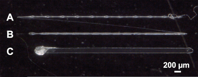
3.10. Using print parameters from Table 1, print a series of test lines with increasing or decreasing z-height to determine the optimal z-height for printing uniform, cylindrical fibers (Fig. 3).
3.11. Upload print path design to the printer and assign which layers will be printed by each printer head.
TIP: (i) The initial layer will have a starting z-height determined in Step 3.10. The z-height between layers is described in Table 1. (ii) The scaffold height will decrease over time due to solvent evaporation. To compensate for this change when switching between printer heads, the z-height of the subsequent printer head must be decreased by 5 μm from the expected z-height determined in Step 3.10.
3.12. After printing, leave scaffolds in the fume hood for at least 24 h to allow complete solvent evaporation.
-
4. Scaffold morphology
4.1. Place scaffolds at −20°C for at least 24 h to achieve a clean cross-section and avoid stretching printed fibers.
4.2. Cut scaffold with a Teflon-coated razor blade to expose its cross-section.
TIP: (i) The razor blade should be perpendicular to the top surface of the scaffold to avoid deforming or stretching the printed fibers. (ii) Cut the scaffolds while they are still attached to the slide to reduce undesired deformation while sectioning.
4.3. Use tweezers to remove the scaffold section from the slide and carbon tape to affix each section in the preferred orientation onto an SEM stub.
4.4. Sputter coat the sample with 10 nm of a conducting layer (i.e., iridium or gold).
TIP: If charging is observed during imaging, increase sputtering time.
4.5. Image scaffolds using SEM to characterize fiber morphology and scaffold architecture (see Anticipated Results).
TIP: (i) Orient samples so the faces of the sectioned fibers are perpendicular to the beam to visualize the full cross-section. (ii) General SEM settings: 5.0 kV beam current, working distance of 18–25 mm, secondary electron detector.
-
5. Peptide presentation
A variety of labeling approaches can be used to characterize peptide presentation and concentration on the 3D-printed scaffolds. One approach is to modify the peptide-PCL conjugates with a bioorthogonal group (i.e., biotin or azide) that will selectively react with its fluorescently tagged complementary moiety. For example, different peptides presented on the same scaffold can be directly and specifically labeled using streptavidin-FITC for biotinylated peptides and DBCO-Cy3 for peptides modified with azides [14]. Another approach is to use labeling techniques based on the specific peptide sequence. For example, amino-Cy3 can be reacted with peptides containing carboxyl groups [16], or fluorescently tagged hyaluronic acid (fl-HA) can bind peptides containing a hyaluronic acid (HA)-binding sequence [17].
-
5.1. The following steps should be used with reference to Table 2 for each labeling procedure:
5.1.1. Prepare the Stock solution. Aliquot and store at −20°C for future use.
5.1.2. Incubate samples in Block solution.
5.1.3. Wash samples following Wash 1 steps.
5.1.4. Incubate samples in Label solution.
5.1.5. Wash samples following Wash 2 steps.
TIP: (i) Use a 24-well plate to keep track of all sample groups, steps, and transfers between washes. Before starting, fill each well with the appropriate solution in order of incubation for a simplified workflow. Use tweezers to move scaffolds between wells. (ii) Protect samples from light using aluminum foil. (iii) For every step, including within each wash, put samples on a rocker for gentle agitation.
5.2. Store samples at 0–8°C protected from light.
5.3. Image using a confocal fluorescence microscope (see Anticipated Results).
-
-
6. Scaffold seeding and cell culture
-
6.1. Prep 24-well culture plates.
6.1.1. Mix Sylgard 184 components together at 10:1 (base:curing agent) ratio. Fill wells 1/3 full and allow Sylgard 184 to harden for 48 h.
6.1.2. Rinse wells with reverse osmosis (RO) water to remove any debris.
6.1.3. In a biosafety cabinet: Soak wells with 70% EtOH for 30 min and rinse twice with sterile RO water.
6.1.4. Sterilize plates under UV light for 2 h.
-
6.2. Prepare and sterilize 3D-printed scaffolds.
6.2.1. Soak scaffolds in 70% EtOH to detach from glass slide.
6.2.2. Use a biopsy punch to cut scaffolds into desired size.
-
NOTE: Next steps must be done in a biosafety cabinet.
6.2.3. Incubate scaffolds in 70% EtOH for 30 min.
6.2.4. Rinse scaffolds with sterile RO water three times for 10 min each.
6.2.5. Incubate scaffolds in sterile 0.1% BSA in RO water for at least 4 h (or overnight) to promote cell adhesion.
-
TIP: Other strategies can be used to promote cell adhesion, such as soaking the scaffolds in serum-containing media prior to seeding.
6.2.6. Rinse scaffolds with sterile RO water three times for 10 min each.
6.2.7. Let scaffolds dry overnight in the biosafety cabinet.
-
6.3. In a biosafety cabinet: Seed cells on scaffolds.
6.3.1. Pin scaffolds to Sylgard 184 layer in the 24-well plates using sterile insect pins (Fig. 4A).
6.3.2. Detach cells from flasks/plates using trypsin and resuspend at a concentration of 10 × 106 cells/ml (or desired concentration).
6.3.3. Pipet the cell solution on top of each scaffold (forming a drop) and place samples in an incubator for 1.5 h (Fig. 4B).
-
TIP: The cell solution volume can be adjusted depending on scaffold size. For reference, a 20 μl drop is suitable for 3-mm diameter scaffolds.
6.3.4. Cover each scaffold in 1 ml of media (Fig. 4C) and culture samples in an incubator.
6.3.5. Change media every 2–3 d. Remove and add media slowly to avoid disturbing scaffolds.
-
-
7. Tissue sectioning and staining
7.1. Fix harvested scaffolds in 4% paraformaldehyde (PFA) for 12–24 h.
7.2. Replace PFA with PBS and store samples at 4°C until ready to section.
-
7.3. Optional step to improve sectioning: infiltrate samples with sucrose the day before sectioning.
6.3.1. Using a razor blade, cut scaffolds in half and place in a microcentrifuge tube.
6.3.2. Incubate in 10% (w/v) sucrose in PBS for 1 h on a rocker.
6.3.3. Incubate in 30% (w/v) sucrose in PBS for 1 h on a rocker.
6.3.4. Incubate in a 50/50 mixture of 30% (w/v) sucrose in PBS and OCT. for 1 h on a rocker.
6.3.5. Store samples in pure OCT. overnight in the fridge.
7.4. Embed samples in OCT. and freeze at −80°C for 5 min.
7.5. Section using a microtome and place sections on glass slides.
TIP: For better tissue adhesion, use positively or negatively charged glass slides.
7.6. Incubate sections with Protease K for 4 min and rinse gently in running water for 30 s.
7.7. Gently rinse with PBS, blot dry, and use a hydrophobic barrier pen to draw a circle around the section.
7.8. Wash with PBS twice for 2 min and blot as much excess buffer as possible from the final rinse.
7.9. Add 5% goat serum in PBS for 1–2 h at room temperature.
7.10. Remove goat serum with a Kimwipe and add the primary antibody at 1:150 dilution in 5% goat serum. For the negative control, add 5% goat serum.
CRITICAL STEP: Place in a moisture chamber in the fridge overnight to avoid drying out sections.
7.11. Prepare 0.1% TWEEN in PBS (1×). Adjust the solution to pH 7.4 using NaOH.
7.12. Wash with 0.1% TWEEN solution three times for 5 min per wash and blot dry.
7.13. Add secondary antibody at 1:200 dilution in 5% goat serum for 2 h at room temperature.
7.14. Wash with 0.1% TWEEN solution three times for 5 min per wash.
7.15. Stain with Hoechst solution at 1:1000 dilution in 5% goat serum for 10 min.
7.16. Wash with 0.1% TWEEN solution three times for 5 min.
7.17. Rinse gently under running water for 2 min.
7.18. Image using a confocal fluorescence microscope (see Anticipated Results).
Figure 1.
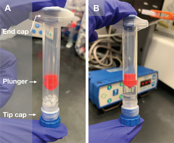
Preparation of a solvent-based ink. A. Pellets of undissolved PCL (37% w/v) are added to a solution of peptide-PCL conjugate in HFIP. The ink is mixed on a wrist-action shaker for 48 h. B. After mixing, the PCL pellets are fully dissolved, resulting in a homogeneously mixed ink.
Figure 2.
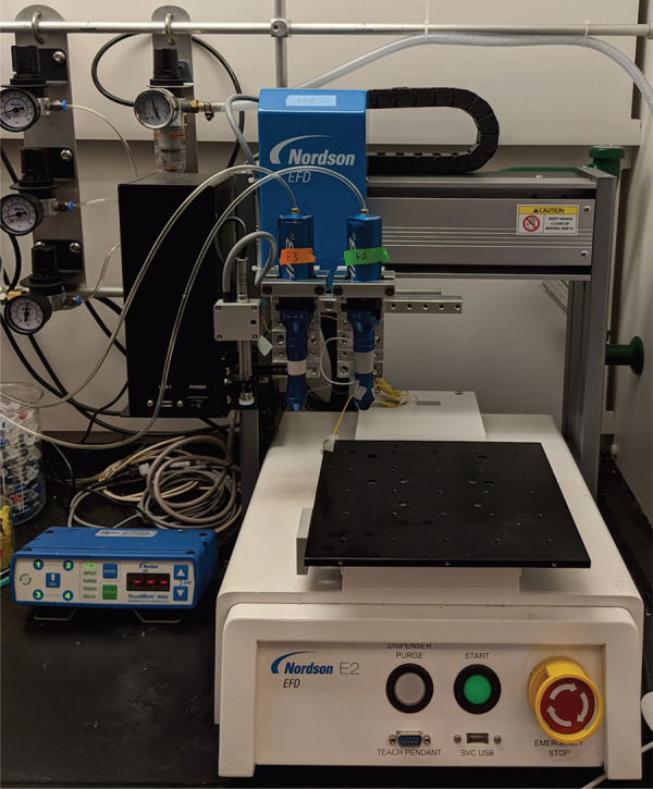
Customized fluid dispensing robot system (Nordson EFD) capable of extrusion-based 3D printing with two print heads.
Table 1.
Commonly used print parameters for solvent-cast 3D printing.
| Needle gauge | 32 G | 30 G | 27 G |
|---|---|---|---|
| Inner diameter (mm) | 0.1 | 0.15 | 0.2 |
| Print speed (mm/s) Layer 1 → Layer 2+ | 0.4 → 0.2 | 0.4 → 0.2 | 0.6 → 0.4 |
| Print pressure (psi) | 70 | 70 | 56 |
| Z-height between layers (μm) | 45 | 60 | 80 |
Figure 3.
Series of test lines printed with decreasing z-height. A. Discontinuous fiber indicating z-height is too high. B. Uniform, cylindrical fiber printed at the optimal z-height. C. Flattened fiber indicating z-height is too low.
Table 2.
Solutions and incubation times used for labeling scaffolds.
| Streptavidin-FITC | DBCO-Cy3 | fl-HA | Amino-Cy3 | |
|---|---|---|---|---|
| Stock | 1 mg/ml streptavidin-FITC in PBS (1×) with 0.1% sodium azide | 5 mM DBCO-Cy3 in DMSO | 0.1 mg/ml fl-HA solution in PBS (1×) | 4 mM amino-Cy3 in 20 mM sodium borate buffer |
| Block | 20 min: 0.5% BSA and 0.05% TWEEN in PBS (1×) |
1 h: 0.2% TWEEN and 0.2% Triton X-100 in PBS (1×) |
Overnight: 0.5% BSA in PBS (1×) |
1 h: 0.2% TWEEN and 0.2% Triton X-100 in PBS (1×) |
| Wash 1 | N/A | 5 min each: Ultrapure water twice |
30 min each: PBS (1×) twice |
5 min each: Ultrapure water twice |
| Label | 1 h: Stock diluted to 1:50 with blocking solution |
1 h: Stock diluted to 1:100 with PBS with 0.5% BSA |
1 h: Stock |
30 min: Stock diluted to 0.1 mM in 20 mM sodium borate buffer; add EDC at 0.2 mM and NHS at 0.2 mM |
| Wash 2 | 30 min each:
|
5–10 min each:
|
30 min each:
|
5–10 min each:
|
Figure 4.
Experimental steps to seed 3D-printed scaffolds. A. Scaffolds are pinned to the Sylgard 184 layer using sterile insect pins. B. A drop of cell solution is pipetted on top of the scaffolds and incubated for 1.5 h. C. Scaffolds are covered with 1 ml of media to maintain in culture.
ANTICIPATED RESULTS
Peptide-PCL conjugates
Each step of the conjugate synthesis should be confirmed using 1H NMR. Proton assignments for PMPI and PCL-mal are based on published spectra [14,17]. The NMR spectra for PCL-mal is normalized to a distinct PCL peak at 4.02 ppm (198H, -O-CH2-, b’).
PCL-mal: NMR showing PMPI successfully conjugated to PCL to form PCL-mal will show proton peaks for PMPI at chemical shifts between 6.5 and 8 ppm (Fig. 5). Chemical shifts to confirm successful PCL-mal synthesis include: 7.6 ppm (4H, aromatic H orthogonal to maleimide, 2), 7.3 ppm (4H, aromatic H orthogonal to carbamate, 2’), and 6.9 ppm (4H, maleimide vinyl, 1). If peak integration for these protons is larger than anticipated, re-dissolve PCL-mal in anhydrous NMP and precipitate in DEE as described in Step 1.3.
Figure 5.
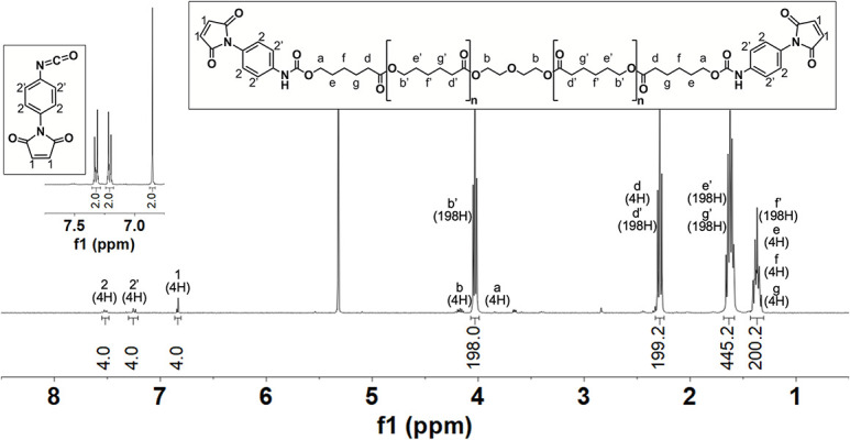
1H NMR (400 MHz, CD2Cl2, TMS) and corresponding chemical structures of p-maleimidophenyl isocyanate (PMPI; inset) and PCL-maleimide.
Peptide-PCL conjugate: NMR spectra of the peptide and peptide-PCL conjugate should be compared to verify and quantify conjugation efficiency. Peaks present in both spectra should be identified and integrated. For example, the peak at 6.61 ppm (4H, d, Ar-H, α) is found in both spectra (Fig. 6). In addition, the disappearance of the maleimide peak at 6.9 ppm (shown in Fig. 5) indicates a successful reaction between the maleimide on PCL-mal and the thiol on the peptide. If NMR shows excess peptide present after synthesis, perform additional washing steps by adding weakly acidic or basic water to improve peptide solubility based on its charge. For example, the top spectra in Figure 6 shows a peak integration of 20 at 6.61 ppm (4H, d, Ar-H, α) when it is expected to be 4, indicating the need for additional washing steps.
Figure 6.
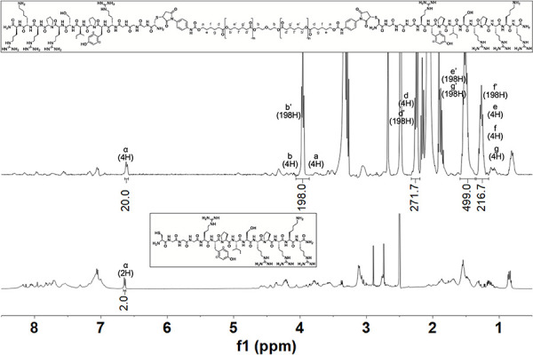
1H NMR (400 MHz, C2D6OS, TMS) and corresponding chemical structures of a peptide-PCL conjugate HAbind-PCL (top) and its corresponding peptide HAbind (bottom).
Scaffold morphology
Print speed, print pressure, polymer concentration in the ink, deposition height, and needle gauge are known to influence the final morphology of 3D-printed structures [18]. These parameters need to be optimized depending on ink formulation and needle gauge to produce consistent cylindrical fiber morphologies and reproducible scaffold architectures (Fig. 7). They also affect the resolution and feature size that can be achieved. For example, we previously printed 37% (w/v) PCL using a 100-μm diameter needle, which resulted in fiber diameters as small as 38.5 μm + 3.1 μm [14] and similar to those shown in Figure 7. Smaller feature sizes may be accomplished by using a smaller needle diameter and modifying the ink formulation.
Figure 7.
Representative scanning electron microscope (SEM) image of a solvent-cast 3D-printed PCL scaffold in (A) top-down view and (B) cross-section view showing consistent fiber diameters and cylindrical morphologies in each printed layer.
Peptide presentation
Fluorescent labeling verifies the presence, spatial location, and concentration of peptides on the surface of 3D-printed scaffolds. To guide OC tissue formation, we synthesized peptide-PCL conjugates with HA-binding (HAbind-PCL, with peptide sequence CGGGRYPISRPRKR) or mineralizing (E3-PCL, with peptide sequence CGGGAAAEEE) peptides to promote human mesenchymal stem cell (hMSC) chondrogenesis [19] or osteogenesis [20], respectively. Spatially organized HAbind/E3-PCL scaffolds were printed using two printer heads with inks containing HAbind-PCL (3 mg/ml) or E3-PCL (18 mg/ml) to control multi-peptide presentation in a continuous construct. Dual-peptide HAbind/E3-PCL scaffolds were labeled using fl-HA or amino-Cy3 to confirm HA-binding and carboxyl group presentation, respectively, in opposing zones (Fig. 8).
Figure 8.
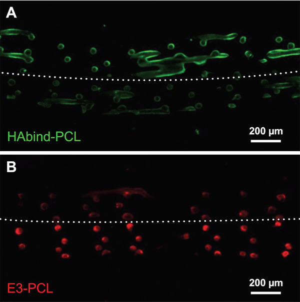
Confocal fluorescence microscopy image of HAbind/E3-PCL scaffold showing peptides are presented in opposing zones. Cross-sections were labeled with (A) fluorescein-tagged HA (fl-HA; green) to bind HAbind peptides or (B) amino-Cy3 (red) to react with carboxyl groups on E3 peptides.
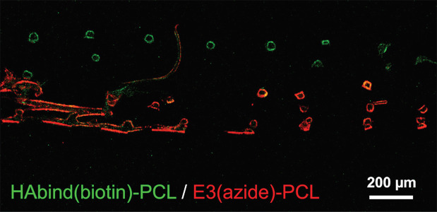
To enable direct and specific labeling of each peptide presented in the 3D-printed scaffolds, we synthesized peptide-PCL conjugates modified with biotin (HAbind(biotin)-PCL) or azide (E3(azide)-PCL). Spatially organized scaffolds printed with HAbind(biotin)-PCL (3 mg/ml) and E3(azide)-PCL (18 mg/ml) were labeled with both streptavidin-FITC and DBCO-Cy3 to visualize peptide organization (Fig. 9). Biotin and azide react only with their complementary group (streptavidin and DBCO, respectively), enabling highly selective reactions even in the presence of other chemistries.
Figure 9.
Confocal fluorescence microscopy image of HAbind(biotin)/E3(azide)-PCL scaffold showing peptides presented in discrete spatial regions. Cross-section was labeled with both streptavidin-FITC and DBCO-Cy3 showing HAbind(biotin) (green) and E3(azide) (red) localization.
In previous studies, we demonstrated ability to control peptide surface concentration and spatial organization in well-defined patterns, such as alternating-fiber or alternating-layer [14]. These broad capabilities can be adapted to create scaffolds with complex designs that mimic the biochemical gradients found in native tissues.
Tissue sectioning and staining
The influence of peptide concentration and organization on tissue formation can be easily explored using this platform. For each application, studies should be performed with scaffolds presenting different peptide concentrations to identify optimal concentrations required to trigger cell activity. Here, desired results with respect to osteochondral tissue formation were achieved using scaffolds printed with 3 mg/ml HAbind-PCL and 18 mg/ml E3-PCL. Tissue formation was analyzed by visualizing collagen (Col) I, II, and X deposition after 42 d of culture within peptide-functionalized scaffolds (Fig. 10). The amount and location of each collagen type demonstrates matrix formation by hMSCs in response to peptide presentation and organization within the 3D-printed scaffolds.
Figure 10.
Matrix formation by hMSCs on HAbind/E3-PCL scaffolds after 42 days of culture. Histological sections are incubated with primary antibodies that bind to collagen (A) I, (B) II and (C) X, followed by a secondary antibody fluorescently tagged with Alexa Fluor 488 (green). Cell nuclei are labeled using Hoescht Dye (blue).
TROUBLESHOOTING
Possible problems and their troubleshooting solutions are listed in Table 3.
Table 3.
Troubleshooting.
| Step # | Problem | Causes | Suggestions |
|---|---|---|---|
| 3.9 | Needle crashes into the slide | Z-height value is too low | Replace needle and start again from Step 3.5 |
| 3.10 | Failed print | Static charge may cause prints to fail | Connect a wire from the grounding screw or metal frame of your printer to the printer bed and needle tip to reduce static build-up. Once grounded, printing can resume as previously described. |
| 4.5 | Top fibers of the scaffold appear flattened | Imaging scaffold surface that was printed directly on the glass slide | Note scaffold orientation when removing it from the glass slide. Attach the side printed directly on the glass to the SEM stub. |
| 5.2 | Fluorescence detected in control scaffolds without peptide modification | Non-specific binding of fluorophores due to insufficient washing | Increase number of wash steps after incubating scaffolds in fluorophore solution. |
Acknowledgments
The authors would like to thank Anne Behre for help with 3D printing, labeling, and imaging scaffolds; and the late Dr. William G. DeLong, Jr for his support and collaboration. The authors also acknowledge Lehigh’s Electron Microscopy and Nanofabrication Facility, Health Research Hub (HRH), and Department of Chemistry Shared Instrumentation. This work was supported by a CAREER Award (DMR-1944914, L.W.C) from the National Science Foundation, a grant from the Pennsylvania Department of Health through the Commonwealth University Research Enhancement (CURE) Program (L.W.C), a grant from the Foundation for Orthopedic Trauma (FOT), and start-up funds from Lehigh University (L.W.C). Additional support from Nordson EFD is also acknowledged for J.W.T. as well as a Grant for Experiential Learning in Health (GELH) through Lehigh University awarded to M.F.
References
- 1.Ansari S, Khorshidi S, Karkhaneh A. (2019) Engineering of gradient osteochondral tissue: From nature to lab. Acta Biomater 87: 41-54. doi: 10.1016/j.actbio.2019.01.071. PMID: [DOI] [PubMed] [Google Scholar]
- 2.Di Luca A, Van Blitterswijk C, Moroni L. (2015) The osteochondral interface as a gradient tissue: from development to the fabrication of gradient scaffolds for regenerative medicine. Birth Defects Res C Embryo Today 105: 34-52. doi: 10.1002/bdrc.21092. PMID: [DOI] [PubMed] [Google Scholar]
- 3.O'Brien FJ. (2011) Biomaterials & scaffolds for tissue engineering. Mater Today 14: 88-95. doi: 10.1016/S1369-7021(11)70058-X. [DOI] [Google Scholar]
- 4.Rashidi H, Yang J, Shakesheff KM. (2014) Surface engineering of synthetic polymer materials for tissue engineering and regenerative medicine applications. Biomater Sci 2: 1318-1331. doi: 10.1039/c3bm60330j. PMID: [DOI] [PubMed] [Google Scholar]
- 5.Stevens MM, George JH. (2005) Exploring and engineering the cell surface interface. Science 310: 1135-1138. doi: 10.1126/science.1106587. PMID: [DOI] [PubMed] [Google Scholar]
- 6.Holmes B, Bulusu K, Plesniak M, Zhang LG. (2016) A synergistic approach to the design, fabrication and evaluation of 3D printed micro and nano featured scaffolds for vascularized bone tissue repair. Nanotechnology 27: 64001. doi: 10.1088/0957-4484/27/6/064001. PMID: [DOI] [PMC free article] [PubMed] [Google Scholar]
- 7.Zhao Y, Tan K, Zhou Y, Ye Z, Tan W. (2016) A combinatorial variation in surface chemistry and pore size of three-dimensional porous poly(ε-caprolactone) scaffolds modulates the behaviors of mesenchymal stem cells. Mater Sci Eng C Mater Biol Appl 59: 193-202. doi: 10.1016/j.msec.2015.10.017. PMID: [DOI] [PubMed] [Google Scholar]
- 8.Cai Y, Li J, Poh CK, Tan HC, San Thian E, et al. (2013) Collagen grafted 3D polycaprolactone scaffolds for enhanced cartilage regeneration. J Mater Chem B 1: 5971-5976. doi: 10.1039/c3tb20680g. PMID: [DOI] [PubMed] [Google Scholar]
- 9.Sun XY, Shankar R, Börner HG, Ghosh TK, Spontak RJ. (2007) Field-driven biofunctionalization of polymer fiber surfaces during electrospinning. Adv Mater 19: 87-91. doi: 10.1002/adma.200601345. [DOI] [Google Scholar]
- 10.Gentsch R, Pippig F, Schmidt S, Cernoch P, Polleux J, et al. (2011) Single-step electrospinning to bioactive polymer nanofibers. Macromolecules 44: 453-461. doi: 10.1021/ma102847a. [DOI] [Google Scholar]
- 11.Li C, Ouyang L, Armstrong JPK, Stevens MM. (2021) Advances in the fabrication of biomaterials for gradient tissue engineering. Trends Biotechnol 39: 150-164. doi: 10.1016/j.tibtech.2020.06.005. PMID: [DOI] [PubMed] [Google Scholar]
- 12.Calejo I, Costa-Almeida R, Reis RL, Gomes ME. (2020) A physiology-inspired multifactorial toolbox in soft-to-hard musculoskeletal interface tissue engineering. Trends Biotechnol 38: 83-98. doi: 10.1016/j.tibtech.2019.06.003. PMID: [DOI] [PubMed] [Google Scholar]
- 13.Khorshidi S, Karkhaneh A. (2018) A review on gradient hydrogel/fiber scaffolds for osteochondral regeneration. J Tissue Eng Regen Med 12: doi: 10.1002/term.2628. PMID: [DOI] [PubMed] [Google Scholar]
- 14.Camacho P, Busari H, Seims KB, Schwarzenberg P, Dailey HL, et al. (2019) 3D printing with peptide-polymer conjugates for single-step fabrication of spatially functionalized scaffolds. Biomater Sci 7: 4237-4247. doi: 10.1039/c9bm00887j. PMID: [DOI] [PubMed] [Google Scholar]
- 15.Chow LW. (2018) Electrospinning functionalized polymers for use as tissue engineering scaffolds. Methods Mol Biol 1758: 27-39. doi: 10.1007/978-1-4939-7741-3_3. PMID: [DOI] [PubMed] [Google Scholar]
- 16.Harrison RH, Steele JAM, Chapman R, Gormley AJ, Chow LW, et al. (2015) Modular and versatile spatial functionalization of tissue engineering scaffolds through fiber-initiated controlled radical polymerization. Adv Funct Mater 25: 5748-5757. doi: 10.1002/adfm.201501277. PMID: [DOI] [PMC free article] [PubMed] [Google Scholar]
- 17.Chow LW, Armgarth A, St-Pierre J, Bertazzo S, Gentilini C, et al. (2014) Peptide-directed spatial organization of biomolecules in dynamic gradient scaffolds. Adv Healthc Mater 3: 1381-1386. doi: 10.1002/adhm.201400032. PMID: [DOI] [PubMed] [Google Scholar]
- 18.Guo S, Gosselin F, Guerin N, Lanouette A, Heuzey M, et al. (2013) Solvent-cast three-dimensional printing of multifunctional microsystems. Small 9: 4118-4122. doi: 10.1002/smll.201300975. PMID: [DOI] [PubMed] [Google Scholar]
- 19.Parmar PA, St-Pierre J, Chow LW, Puetzer JL, Stoichevska V, et al. (2016) Harnessing the versatility of bacterial collagen to improve the chondrogenic potential of porous collagen scaffolds. Adv Healthc Mater 5: 1656-1666. doi: 10.1002/adhm.201600136. PMID: [DOI] [PMC free article] [PubMed] [Google Scholar]
- 20.Karaman O, Kumar A, Moeinzadeh S, He X, Cui T, et al. (2016) Effect of surface modification of nanofibres with glutamic acid peptide on calcium phosphate nucleation and osteogenic differentiation of marrow stromal cells. J Tissue Eng Regen Med 10: doi: 10.1002/term.1775. PMID: [DOI] [PubMed] [Google Scholar]


