Abstract
This paper reports long-term evaluation of a micropackage technology for an implantable MEMS pressure sensor. The all-polymer micropackage survived 160 days when subjected to accelerated lifetime testing at 85 °C in a 1% wt. saline solution. The package shows minimum effect on sensors’ sensitivity and nonlinearity, which deviated by less than 5% and 0.3%, respectively. A 6-month in vivo evaluation of 16 MEMS-based pressure sensors demonstrated that the proposed micropackage has good biocompatibility and can protect the MEMS pressure sensor. To the best of our knowledge, these results establish new lifetime records for devices packaged using an all-polymer micropackaging approach.
Keywords: Non-hermetic micropackage, encapsulation of biomedical devices, Parylene-C, PDMS, pressure sensor, packaging
INTRODUCTION
Motivation
Packaging-related issues that include performance drift, large form factors, and tissue compatibility have in part, limited widespread adoption of implantable pressure sensors. Traditional hermetic packages based on metal, glass, and silicon exhibit long lifetimes, are difficult to miniaturize and lack the mechanical flexibility required to minimize strain on the surrounding tissue. Polymeric packages offer mechanical flexibility, good biocompatibility, and reasonable lifetimes [1–5]. Many groups have demonstrated short-term viability of polymeric packages [6–7]; however, few have reported long-term testing results especially using in vivo tests. In this paper, we report for the first time, the results of a study that included both in situ long-term acceleration testing and in vivo animal implantation trials to evaluate the feasibility of an all-polymer micropackage technology for pressure sensing applications.
Hypothesis
A hypothesis is formulated for realizing an ideal non-hermetic polymer-based micropackage technology for MEMS-based implantable pressure sensors that has a usable lifetime in years if the micropackage materials have stable electrical and mechanical properties, especially:
There is no cross micropackage defect, no delamination due to weak bonding, no cavity for water vapor to condense, no ionic contamination, and the insulating materials of micropackage retain high resistivity when saturated with water vapor over the expected lifetime.
The packaging materials have stable tissue-like mechanical properties, which will not attenuate nor distort the pressure signal from tissue, nor load tissue.
The electrical insulation of the protect layer will be intact, if there is no cross-micropackage defect. Accordingly, if there is no cavity and no delamination, water will not condense. If there is no contamination, the osmosis of water is reversed compared to the case in hermetic package, so that water will be drained from the micropackage into outside body fluid. At this point, the vapor pressure in the package is in equilibrium with the external environment, and the equilibrium period might be extended to ten years. The lifetime of the non-hermetic package is then determined by the equilibrium period, which is terminated when water condensation in unbound cavities or on the substrate surface leads to a decrease in the resistivity below the threshold value.
Medical grade thin film and liquid form polymeric materials can adapt their physical shape according to the local pressure generated by nearby tissue. This adaptiveness can last long if the whole package is design well.
Concept
In order to realize the electrical and mechanical properties according to our hypothesis, a special package diagram for MEMS sensor is developed with long-lifetime polymeric materials [1–4]. As shown in Fig. 1, the concept design places the Parylene-C layer beneath the PDMS. A porthole is machined through the substrate and aligned with the diaphragm of the MEMS pressure sensor, with the sensor and its window forming a cone-shape cavity. The opening of the pocket is covered with a flexible and long lasting corrugated membrane made of Parylene-C and PDMS. The pocket is filled with low viscosity silicone gel. This design of corrugated membrane will adapt its physical shape according to the local pressure generated by nearby tissue.
Figure 1:
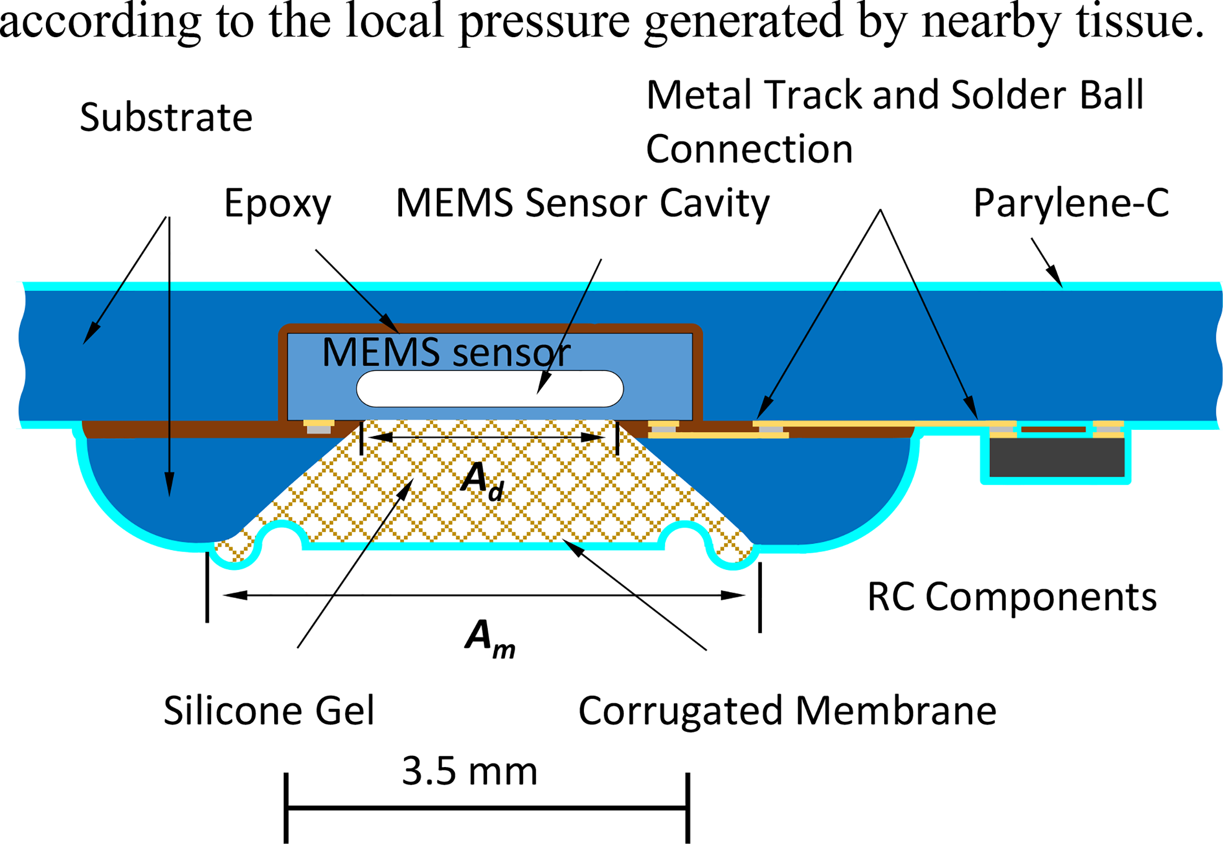
Diagram of micropackaged MEMS pressure sensor in a typical medical microsystem. The corrugated membrane is one key to keep the sensitivity and nonlinearity constant during long-term implantation.
EXPERIMENTS
Micropackage Process and Evaluation
The proposed package process has following four steps as shown in Fig. 2 a–d:
Figure 2:
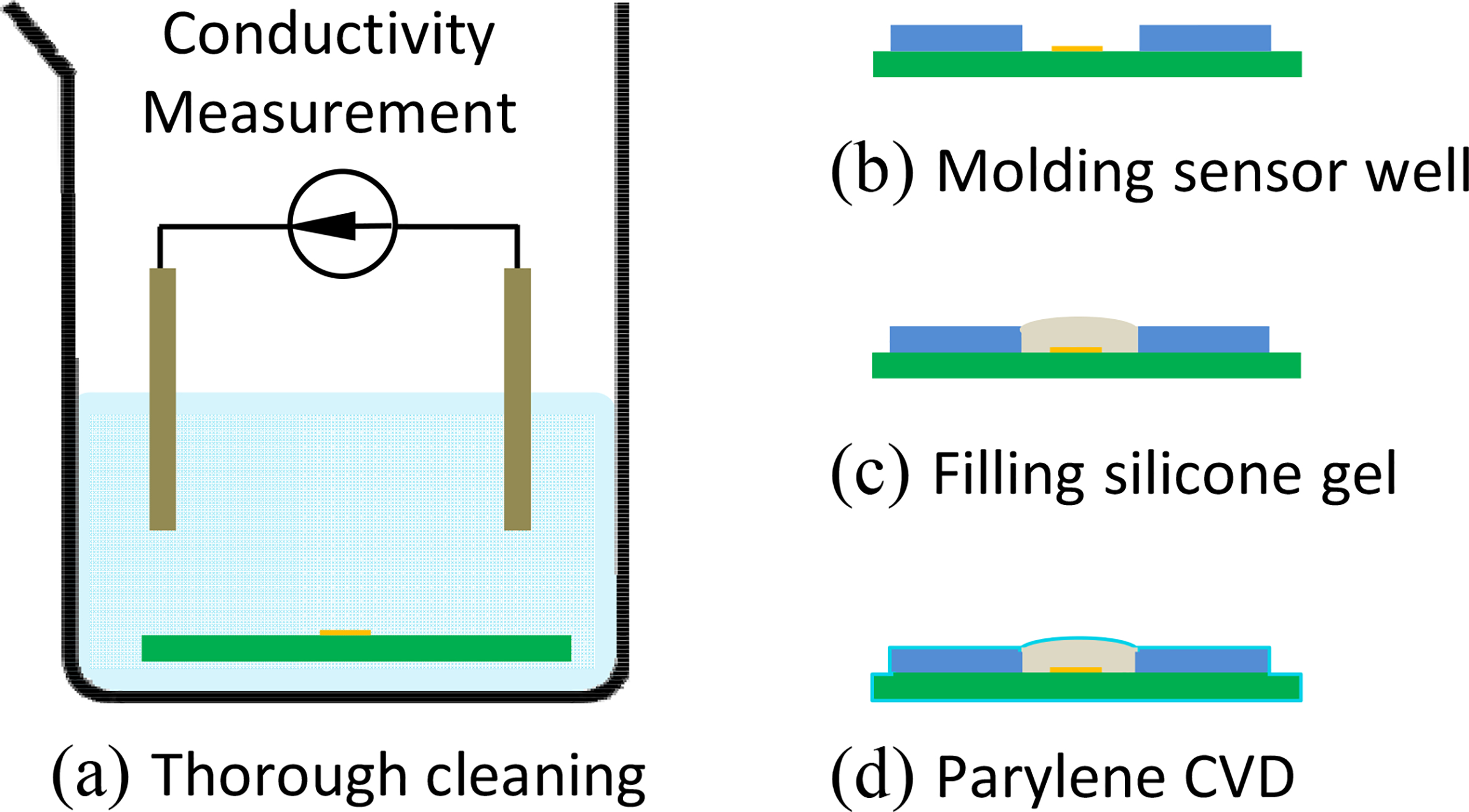
Main steps of proposed micropackaging process. (a) Thorough cleaning to remove ionic contamination. Conductivity of rinsing solution was characterized as an index of device cleanness. (b) Sensor well was built from PDMS mold. (c) Silicone gel was filled into sensor well and cured with a flat or convex shape. (d) Two 5-μm thick layers of Parylene-C were deposited to protect the soft silicone gel.
First, the devices were cleaned thoroughly: the devices were rinsed by solvents (IPA, acetone) and de-ionized (DI) water for hours, until there is no more measurable ionic contamination dissolved into solvent and DI water. The ionic contamination level was evaluated by measuring the resistivity of the solvent and DI water. The devices are clean, if the resistivity of rinsing solvent/DI water is above 80% of the value of fresh solvent/DI water. The sequence of rinsing is acetone, IPA, and DI water. After cleaning, devices were dried in vacuum for 30 min. Additional clean steps with saponifier (SyberKleen 2000, Superior Flux & Mfg. Co.) can be used to remove solder flux that was induced in reflow soldering.
Second, a sensor well was built by drilling PCB substrate or molding process. The well was built with epoxy (Hysol FP4650) and shaped by a PDMS negative mold. The PDMS mold was copied from a 3D printed positive mold.
Third, liquid silicone gel (Sylgard® 527, 1:1 ratio) was mixed, degased and filled in the sensor well that was built in before mentioned step. The degased silicone gel was then fully cured under vacuum and at room temperature. The lower curing temperature is aimed to slow the curing process for fully degassing purpose. The cured silicone gel shape should be convex or flat, but not concave, as shown in Fig. 2–b. These two shape are aimed to release the residues stress caused by the vacuum in next Parylene-C step.
Finally, Parylene-C was deposited with two 5-μm thick layers, using (PDS 2010, SCS Co., USA) equipment. In order to increase bonding strength: adhesion promoter A-174 (PDS 2010, SCS Co., USA) were used. All the above processes were conducted in CWRU Class 100 clean room to reduce the dust contamination.
The long-term evaluation of the proposed micropackage includes an accelerated lifetime test at 85 °C in a 1% wt. saline solution and a 6 month in vivo evaluation.
In the accelerated lifetime test, two commercial MEMS pressure sensors (ASB1200VR, EPCOS Inc.) were packaged as the process described in Fig. 1 and Fig. 2. The packaged sensors with flat and convex diaphragm are shown in Fig. 3–b. The sensors were connected by metal wire for testing purpose. The metal wires were protected by Parylene-C in the same process, during which sensors were packaged. The tethered pressure sensors were soaked in 85 °C in a 1% wt. saline solution for more than 160 days. The sensors were periodically taken out from the saline solution to a room temperature environment for evaluation. A customized setup was built for evaluation, including a pump, a two-inlet pressure chamber, and a LabVIEW-based logging system as shown in Fig. 3–a. The automatic pump generates ramp pressure by pushing/pulling a syringe. The ramp pressure is applied to the pressure chamber, which seals an unpackaged reference sensor and a sensor under test. A customized LabVIEW program running on a computer logged the readout of reference sensor and sensor under test simultaneously. The result is analyzed in next section.
Figure 3:
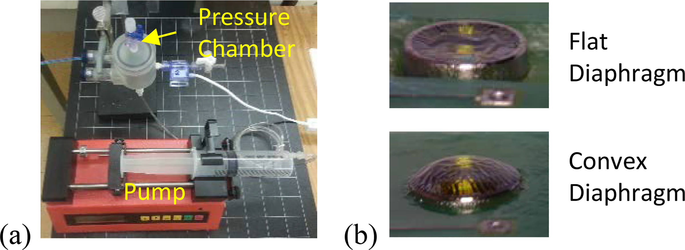
(a) Test setup and (b) view of two proposed sensor micropackage. (b) Top is flat diaphragm while bottom is convex. The corrugation is due to release of vacuum caused expansion of silicone gel.
In the 6-month in vivo evaluation, sixteen telemetry devices were fabricated for evaluation. As shown in Fig. 4–b, each telemetry device consisted of a commercial MEMS pressure sensor (ASB1200VR, EPCOS Inc.), a microcontroller (PIC12F1822, Microchip Inc.), a lithium battery (CR1225 Renata Batteries Inc.), a SMD inductor antenna and other passive components. Pressure samples were transmitted at 10 Hz using ASK modulation of a 4-MHz carrier to a receiving antenna placed 10 cm away. The implanted device drew 400 μA while transmitting and 30 nA in sleep mode. To save power, the implant automatically entered sleep after 3 minutes of usage and was selectively activated by external transmission of a “wake up” signal. With an average usage rate of 15 minutes/week, the implant could run for longer than 3 years before depleting the battery.
Figure 4:
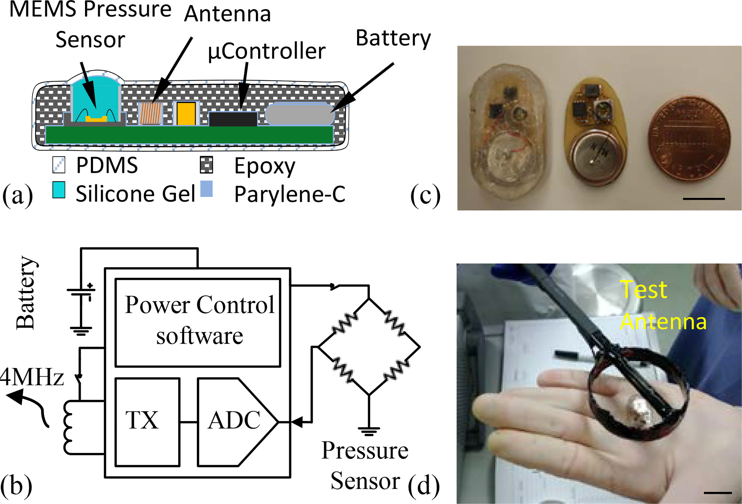
Test setup for 6-month in vivo evaluation of rat implant. (a) Diagram of micropackaged device. (b) View of unpackaged and packaged implant. (c) Diagram of implantable telemetry sensor. (d) Pre-implant and explant testing of device function. The scale bars in (b) and (c) are 10 mm.
As shown in Fig. 5–a, the devices were packaged with two 5-μm-thick layers of chemical vapor deposited (CVD) Parylene-C (Special Coating Systems Inc.), as well as molded epoxy (EB-107LP-2, EpoxySet Inc.) and roller casted PDMS (MDX4–4210, Dow Corning Corporation Inc.). The MEMS pressure sensors were packaged the same as described in Fig. 1 and Fig. 2, with silicone gel, sensor well, parylene-C/PDMS outlayer. The thick epoxy is aimed to smooth the variance caused by various on-board components.
Figure 5:
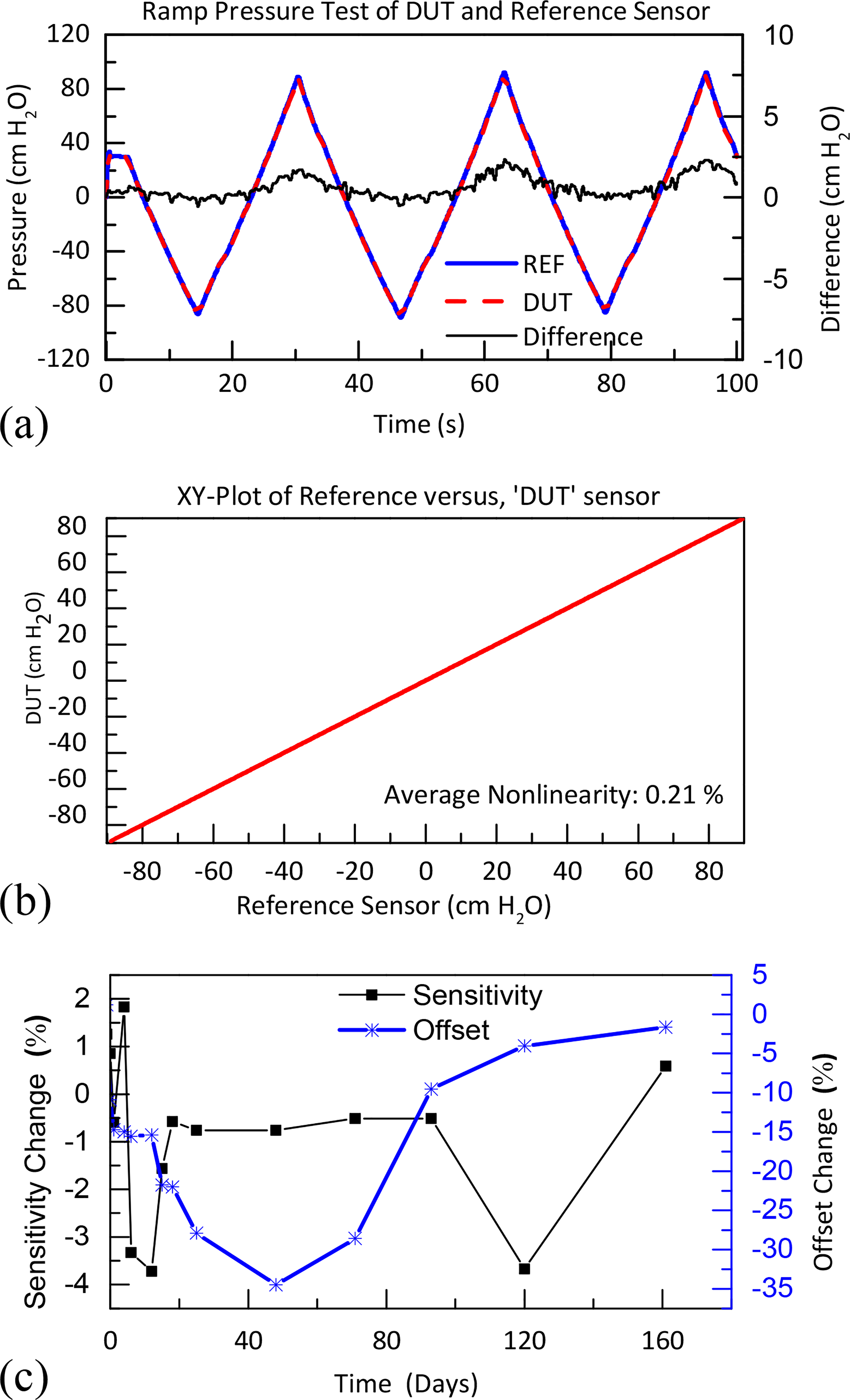
(a) Comparison test with device under test (DUT) and unpackaged reference sensor with ramp pressure. (b) and (c) are results of long-term acceleration for a packaged micro pressure sensor after 160 days. (c) Nonlinearity analysis, sensitivity, and offset change of DUT sensor.
RESULTS AND DISCUSSION
Aging Factor
We calculated the acceleration ratio to be 28, based on the acceleration ratio doubles with every 10 °C increase, given the body and test temperature of 37 °C and 85 °C respectively [8, 9], in consistent with 38 in literature [10] and 30 in [11]. Thus the extrapolated lifetime from 160 days in 85 °C to 37 °C is around 12 years.
Sensor Performance
During benchtop acceleration testing, two packaged commercial MEMS pressure sensors lasted for 167 days in 1% wt. saline solution at 85 °C. The thickness of Parylene-C film used was 10 μm and the epoxy was 320 μm. The packaged sensors were tested periodically in the setup shown in Fig. 3–a, along with an unpackaged reference sensor. Test results are shown in Fig. 5–a. The nonlinearity data are presented in Fig. 5–b. The sensitivity change was less than 5%, and the offset 40%, as seen in Fig. 5–c. The offset is due to expansion of the silicone gel absorbing water, which is calibrated in our animal experiments and can be reduced by increasing the corrugation of sensing membrane in Fig. 1.
Biocompatibility
All-polymer micropackage was tested using rats (N=16), with devices implanted subcutaneously at the shoulder and base of the tail. All implant evaluations followed ANSI/AAMI/ISO standard 10993–6. The test bench and explanted device are shown in Fig. 4–b and Fig. 4–d. No acute/chronic inflammation or granulation tissue was observed, as the biopsy result shown in Fig. 6 a–d.
Figure 6:
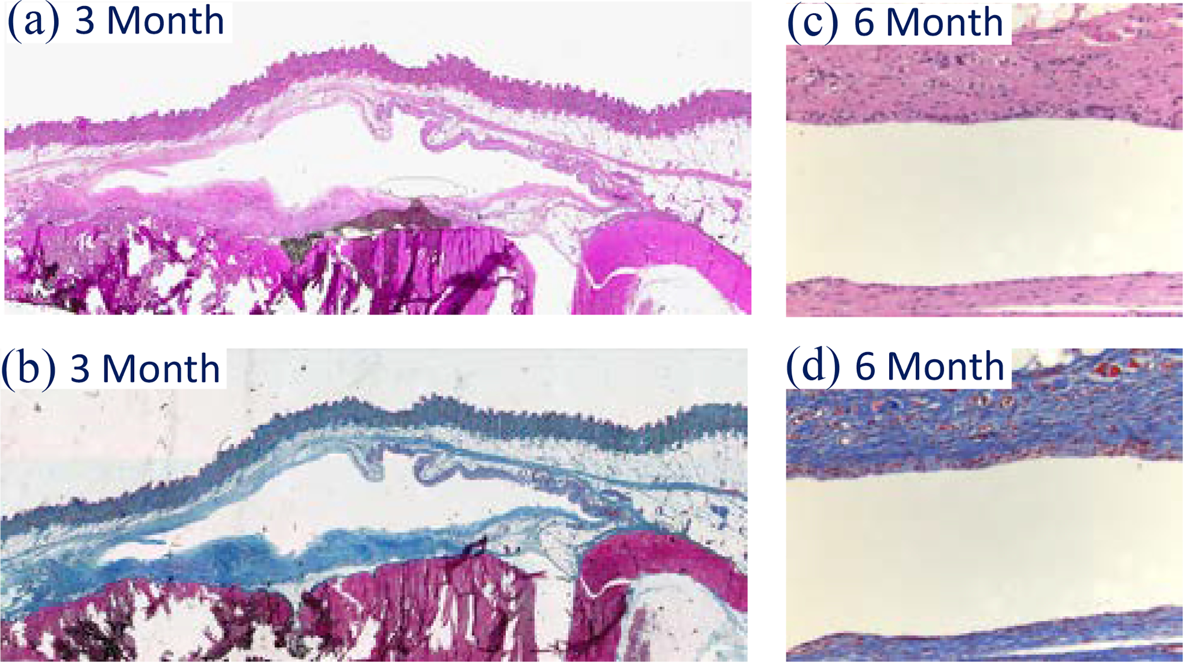
Biopsy result of 3- and 6-month biocompatibility evaluation without acute/chronic inflammation nor granulation tissue. (a) and (c) are stained with trichrome; while (c) and (d) with hematoxylin & eosin (H&E). The amplification is 20X.
CONCLUSIONS
A long-term micropackage technology using all polymeric material has been developed for an implantable MEMS pressure sensor. The affect of package on pressure sensor was evaluated by a 160-day accelerated lifetime testing at 85 °C in a 1% wt. saline solution. The package shows minimum effect on sensors’ sensitivity and nonlinearity, which deviated by less than 5% and 0.3%, respectively. The biocompatibility of the package was evaluated by a 6-month in vivo implantation of 16 MEMS-based pressure sensors. The result demonstrated that the proposed micropackage has good biocompatibility and can protect the MEMS pressure sensor. To the best of our knowledge, these results establish new lifetime records for devices packaged using an all-polymer micropackaging approach. The nonhermetic package is under modification to accommodate a custom ASIC [12] and wire-bonded battery, for a 1-year implant evaluation according to ANSI/AAMI/ISO 10993-6.
ACKNOWLEDGEMENTS
This work is supported by NIH R-21-EB014442 and Louis Strokes Cleveland Medical Center of the Department of Veterans Affairs, the Advanced Platform Technology (APT) Center, and Case School of Engineering.
REFERENCE
- [1].Ko WH and Wang P, “Nonhermetic Micropackage for Implant MEMS Systems,” in Proc. Ann. Int. Conf. IEEE Eng. Med. Biol. Soc., Seattle, WA, USA, Sept. 28, 2013. [Google Scholar]
- [2].Wang P, Sun D, Majerus SJA, Lachhman SB, Li SX, Damaser MS, et al. , “Implantable Pressure Telemetry Device With Thin Film Micropackage,” in Ann. Int. Conf. IEEE Eng. Med. Biol. Soc., Seattle, WA, USA, Sept. 28, 2013. [Google Scholar]
- [3].Wang P, Lachhman SB, Sun D, Majerus SJA, Damaser MS, Zorman CA, et al. , “Non-Hermetic Micropackage for Chronic Implantable Systems,” presented at the Proc. 46th Int. Symp. on Microelectronics, Orlando, FL, USA, Oct. 3, 2013. [Google Scholar]
- [4].Wang P, Majerus SJA, Anderson JM, Damaser MS, Zorman CA, and Ko WH, “Long-Term Implant Evaluation of Non-hermetic Micropackage Technology,” in Proc. Ann. Int. Conf. IEEE Eng. Med. Biol. Soc., San Antonio, TX, Oct. 22–25, 2014. [Google Scholar]
- [5].Bu LP, Cong P, Kuo HI, Ye XS, and Ko WH, “Micro Package of Short Term Wireless Implantable Microfabricated Systems”, in Proc. Ann. Int. Conf. IEEE Eng. Med. Biol. Soc., Minneapolis, MN, USA, Sept. 2–9, 2009, pp. 6395–6399. [DOI] [PubMed] [Google Scholar]
- [6].Chitnis G and Ziaie B, “A ferrofluid-based wireless pressure sensor,” J. Micromech. Microeng, vol. 23, p. 125031, 2013. [Google Scholar]
- [7].Chitnis G, Maleki T, Samuels B, Cantor LB, and Ziaie B, “A minimally invasive implantable wireless pressure sensor for continuous IOP monitoring,” IEEE Trans. Biomed. Eng, vol. 60, pp. 250–256, 2013. [DOI] [PubMed] [Google Scholar]
- [8].Hemmerich KJ, “General aging theory and simplified protocol for accelerated aging of medical devices,” Medical Plastic and Biomaterials, vol. 5, pp. 16–23, 1998. [Google Scholar]
- [9].Hukins D, Mahomed A, and Kukureka S, “Accelerated aging for testing polymeric biomaterials and medical devices,” Med. Eng. Phys, vol. 30, no. 10, pp. 1270–1274, 2008. [DOI] [PubMed] [Google Scholar]
- [10].Zhang R, “The study of MEMS acoustic sensor for totally implantable hearing-aid system and micropackage technology for implantable devices,” M.S. thesis, Dept. Elect. Eng. & Comp. Sci., Case Western Reserve University, Cleveland, OH, USA, 2011. [Google Scholar]
- [11].Chang JHC, Liu Y, Kang DY, and Tai YC, “Reliable Packaging for Parylene-based Flexible Retinal Implant,” in Dig. 17th Int. Conf. Solid-State Sensors, Actuators, & Microsystems (Transducers’ 13), Barcelona, Spain, Jun. 16–20, 2013, pp. 2612–2615, [Google Scholar]
- [12].Majerus SJA, Garverick SL, Suster MA, Fletter PC, Damaser MS, “Wireless, ultra-low-power implantable sensor for chronic bladder pressure monitoring”, Acm J. Emerg. Tech. Com, vol. 8, no. 2, Article 11, 2012. [DOI] [PMC free article] [PubMed] [Google Scholar]


