Abstract
Implanted pressure sensors suffer from long-term offset drift due to atmospheric changes, package moisture absorption, and patient factors such as posture, implant shift, and tissue overgrowth. Traditionally, wide dynamic range instrumentation is used to satisfy the full-scale and sensitivity requirements for a given application. Transmission of extra bits greatly increases the power draw of an implanted medical device, and simple AC-coupling cannot monitor static pressures. We present a mixed-signal offset cancellation loop to maximize the AC dynamic range of instrumentation circuitry. A digital implementation allows for designer control of the cancellation system time constant and was specifically designed for power-gated pressure sensors. Pressure offset is calculated by digital integration and a bipolar IDAC with coarse/fine tuning injects an offset-cancelling current into a standard piezoresistive MEMS pressure sensor. Test results showed a dynamic range increase of 2.9 bits using dynamic offset cancellation, for an effective sensing range of 11 bits using 8-bit instrumentation. The measured step response of the system showed an overall highpass response of 2.3 – 3.8 mHz. This approach is therefore relevant for bio-sensing of pressures in organs with a very slow physiologic response, e.g. the bladder.
I. Introduction
Pressure sensing implantable medical devices have been studied for decades and have been deployed into arguably every major physiologic system in humans and animals. The emergence of MEMS pressure sensors in the past two decades has further cemented the concept that pressure may be feasibly monitored in any organ, as long as the implantable system can be sufficiently miniaturized for surgical deployment and long-term retention at the implant location. As sensors and batteries have shrunk, the possibility of chronic implantation of tiny, pressure-sensing implants has become a reality [1] [2] [3].
Any chronically-implanted pressure sensor, however, must account for several factors: sensor stability, sensing dynamic range and system power consumption. Sensor stability is affected by a multitude of factors, including tissue overgrowth and moisture absorption into polymer coatings [4]. Patient posture or elevation changes can introduce DC pressure shifts that appear as offsets. Over time, sensing dynamic range is lost if the drifting sensor offset exceeds the linear range of instrumentation circuitry. Finally, reducing power consumption is key to maintaining a small system size and extending the lifespan of battery charge/discharge cycles.
We have developed a custom implantable pressure sensor for wireless bladder pressure sensing [5]. The human bladder—like organs in the gastrointestinal, colorectal, and cerebrospinal systems—undergoes relatively slow physiologic pressure changes within a limited range. However, in an ambulatory subject, high-frequency motion artifacts and drifting sensor offset greatly increase the required system dynamic range to prevent sensitivity loss in the presence of pressure transients. For ultra-low-power implantable devices, wide-range instrumentation circuitry increases IC size, design complexity, amplifier settling ADC conversion time, and power consumption. Furthermore, transmission of extra data bits greatly affects the overall implantable device power draw.
The simultaneous need for wide-dynamic-range instrumentation circuitry and very low total implant power consumption is a challenging constraint that has been widely studied in neural sensing ICs [6] [7]. Here, we present a linear approach to cancelling the long-term offset drift of implanted pressure sensors (Fig. 1). The circuitry effectively splits high- and low-frequency sensor signals to increase the overall sensing dynamic range including DC pressures.
Fig. 1.
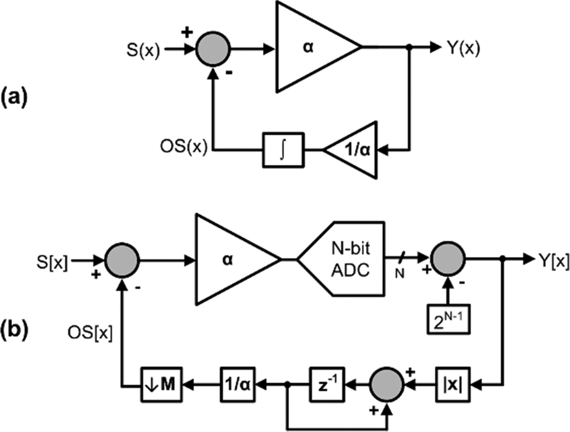
The continuous-time approach to drift cancellation of S(x) (a) uses an integrator in feedback to transform an amplifier into a highpass filter. A discrete-time approach for N-bit instrumentation (b) is more amenable to use with power-gated sensors in which S[x] is only valid at discrete time points.
II. Linear Pressure Sensor Drift Cancellation
Bladder pressures comprise a slow-changing, vesical pressure, on which is superimposed more rapid abdominal pressure changes. Abdominal pressure is ever-changing due to atmospheric pressure changes and physiological factors such as posture variations and tissue aging. Other sources of sensor offset such as temperature response, packaging material aging, and tissue overgrowth cause an unpredictable, non-monotonic offset drift. Simple AC-coupling is not an appropriate option as static bladder pressure is an important parameter to measure. Furthermore, AC-coupling is not useful in a typical power-gated architecture or in an RF-powered device in which the sensor is powered in a regular but discontinuous fashion.
To maintain accuracy over a wide dynamic range and to eliminate implant-related offset effects, we propose a linear offset-removal loop (Fig. 2) which continuously varies the value of a current-output digital-to-analog converter (IDAC) to maintain the pressure sensor at ½ the full-scale instrumentation dynamic range. In this example, a sensing dynamic range of 11-bits is obtained with 8-bit instrumentation circuitry.
Fig. 2.
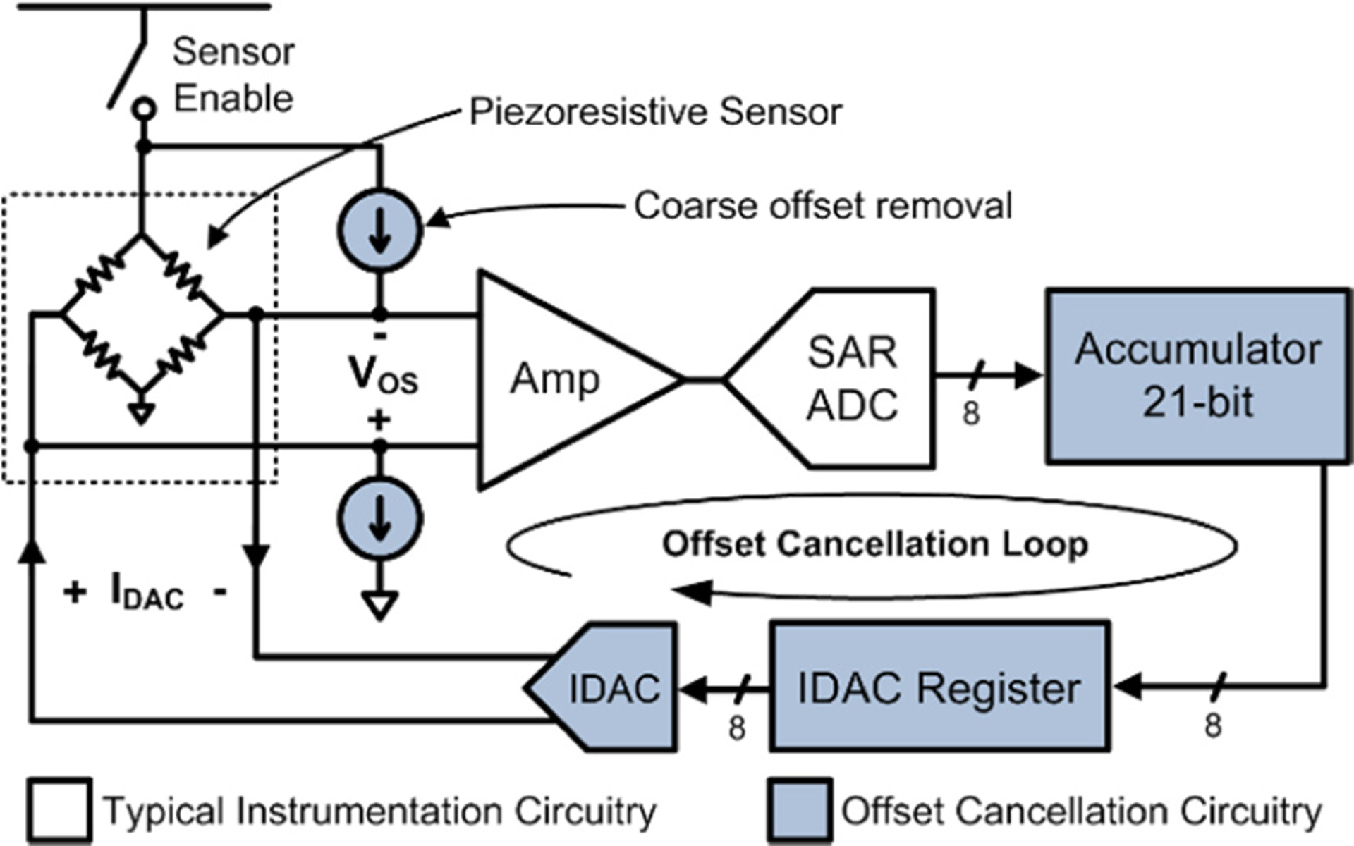
Simplified block diagram of the dynamic offset-cancellation circuit. The integrating feedback loop uses a bipolar IDAC to continuously adjust the pressure sensor offset to maintain an average ADC output of ½ full-scale.
The offset-cancellation circuitry uses an accumulator to perform a long-term average, with ADC samples added to the accumulator as signed operands. Every 32 samples, the 8 most-significant bits of the accumulator are copied to the IDAC register, which sets the IDAC output current. This procedure divides the accumulator value by , where NA is the accumulator length. Thus the value copied to the IDAC register represents a running average of the pressure samples. In steady state, the accumulator value varies with AC pressure changes, but the average value remains the same (assuming zero-mean pressure changes).
To prevent saturation of the instrumentation circuits, offset cancellation operates continuously while samples are acquired. The cancellation feedback loop maintains an average output of 128, or half of the ADC full-scale range, at the ADC output. This maximizes the amplifier and ADC dynamic range, allowing for high resolution measurements of quick pressure changes (the ADC samples) and lower resolution measurements of low-frequency pressure baseline drift (the offset IDAC values). Pressure information is not lost with this technique, since both the ADC samples and the offset values are wirelessly transmitted within data packets. Since normal filling information is transmitted as offset values, clinicians should be able to separate the average level of bladder pressure (useful to measure bladder fullness, compliance, etc.) while still benefiting from enhanced accuracy of high-frequency events such as bladder contractions.
A. Offset-Cancellation Frequency Response
The feedback loop of Fig. 2b may be analyzed using the circuit of Fig. 2. Here we generalize the circuit parameters as described in Table 1 for instrumentation of resolution NI bits.
Table 1.
Parameters of the offset cancellation system for time-constant calculation.
| Variable | Description | Nominal Value |
|---|---|---|
| FS | ADC sampling frequency (Hz) | 100 |
| FI | IDAC update rate (Hz) | 0.20 |
| NA | Accumulator length (bits) | 22 |
| ND | IDAC resolution (bits) | 8 |
| RDA | Average ratio of ADC codes per IDAC code | 6 – 9* |
depending on amplifier gain setting
The system large-signal step response is initially limited by an IDAC linear slew rate of codes per sample. Once the pressure offset falls within the range, the offset-cancellation system performs linearly. Therefore, the system has a predictable frequency response that may be precisely defined by an effective time constant τOS given by
| (1) |
The time constant is a function of the accumulator size (NA), the IDAC resolution (ND), scaling term RDA, the ADC sample rate FS and the IDAC update rate FI. The factor RDA is a system parameter describing the IDAC LSB “weight” in ADC codes, or how many ADC codes are equal to a 1-bit change in the IDAC output. This factor is essentially the loop gain of the offset cancellation system.
The offset cancellation system has a low-pass frequency response with corner frequency . However, once this low-pass system is coupled back into the instrumentation circuitry as negative feedback, the frequency response is flipped. Thus, the offset cancellation loop creates an overall highpass response such that AC pressures may be quantized at the instrumentation dynamic range, while drifting DC offsets are removed. The nominal values for the offset cancellation system were chosen to produce a long time constant of 68–46 seconds, for a high-pass corner frequency of 2.3–3.5 mHz, for amplifier gain settings of 150–260 V/V. This time constant was chosen to be long enough such that slow, naturally-occurring pressure changes are captured at full resolution, while rejecting long-term drift which could lead to instrumentation saturation.
B. Offset-Trimming IDAC
Pressure sensor offset is removed by a coarse adjustment followed by a fine-scale trim IDAC (Fig. 3). The differential topology maintains a constant common-mode input level at the instrumentation amplifier (INA). While the IDAC has 8-bit resolution and full-scale output ±IOS, coarse atmospheric offset removal is provided through fixed current sources of value IATM. The atmospheric offset is static and positive while drifting offset changes dynamically based on implant factors and is trimmed continuously by the IDAC. Power is saved between sensor samples with power-gating switches.
Fig. 3.
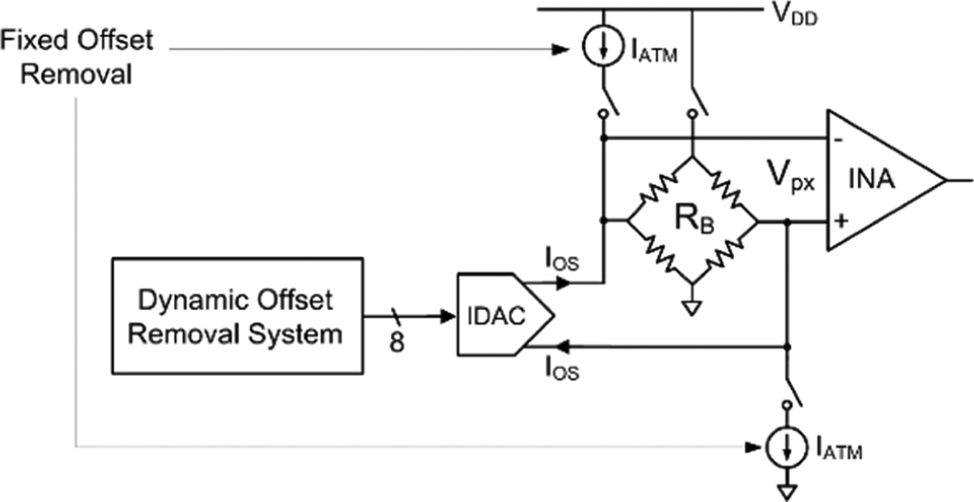
Pressure sensor drift is canceled by injecting a differential current IATM+IOS from coarse, fixed current sources and a trimming IDAC.
The output of the pressure sensor, Vpx, may be expressed as
| (2) |
where VATM and VOS represent the atmospheric and drifting offset, respectively, and RB is the pressure sensor bridge resistance. Thus, scaling of IATM and IOS can be matched to a specific pressure sensor and offset characteristics.
An 8-bit IDAC was implemented using a 7-bit binary-weighted current source array (Fig. 4). Bipolar operation was achieved by using sign-magnitude binary format. For negative IDAC outputs, the IDAC magnitude is maintained and a polarity switch reverses the current source direction. This leads to a double mapping in which codes 2N−1 and 2N−1-1 both produce zero IDAC output. This beneficial dead zone spans the steady-state quiescent point of the offset-cancellation feedback loop and introduces hysteresis which prevents limit cycles.
Fig. 4.
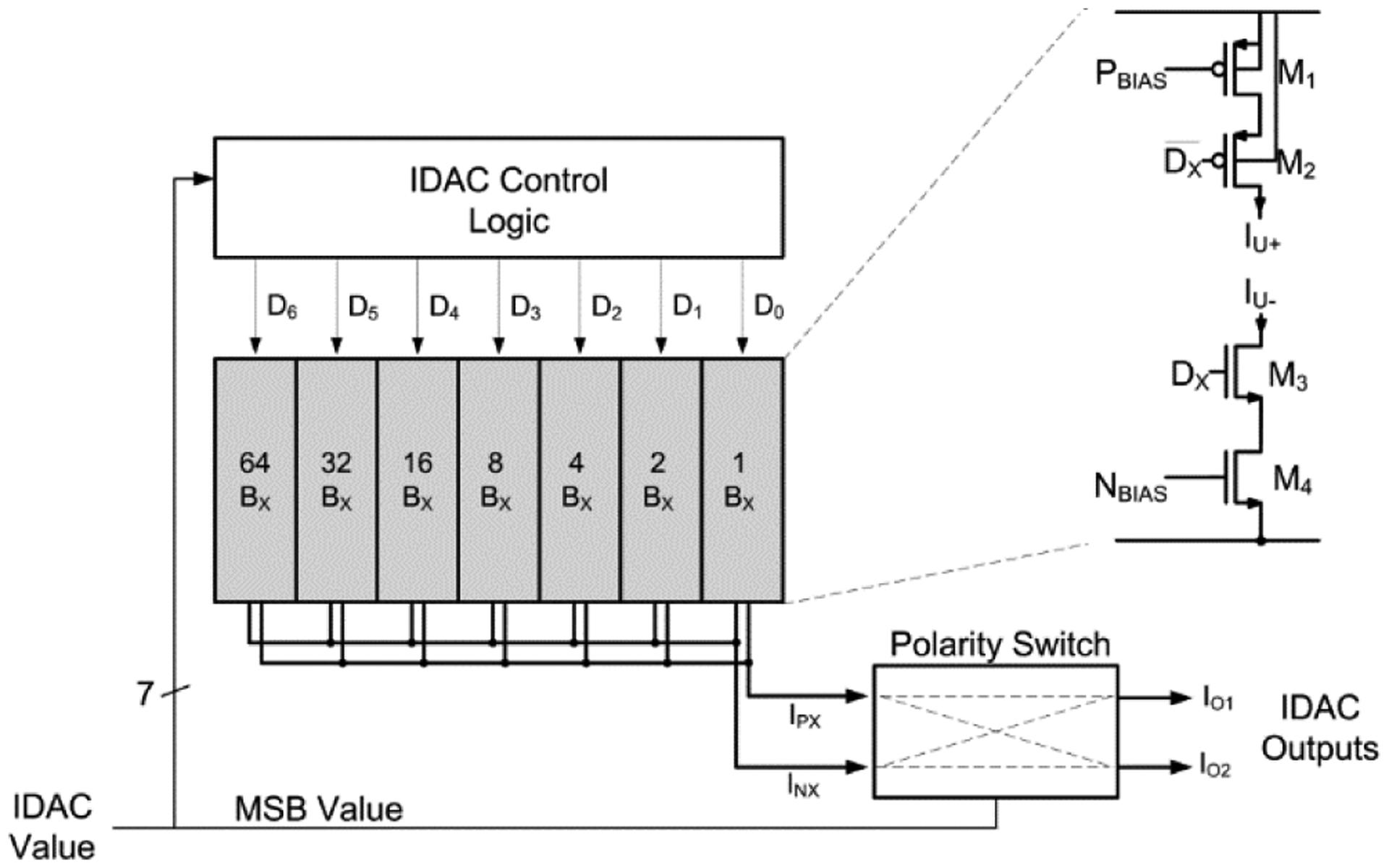
The IDAC structure consists of a 7-bit binary-weighted array of unit current elements, a polarity switch to enable bipolar operation, and control logic to determine sign and magnitude based on the programmed value.
Nominal values for the IDAC currents were chosen for the EPCOS C29 sensor [8], which has VATM=32 mV at 1 atm and RB=2.7 kΩ. Current scaling of IATM=20 μA and full-scale IDAC IOS=7 μA were chosen to provide a pressure sensor offset cancellation range of 34–74 mV. The fixed offset IATM was slightly higher than the inherent sensor VATM to allow for inevitable offsets caused by packaging materials. In this example the system may dynamically cancel pressure offsets of 1.69 ± 0.63 atm.
III. Dynamic Range Enhancement Example
Effectively, the proposed drift cancellation approach is a method for enhancing the AC dynamic sensing range for instrumentation circuitry. Similar robustness to sensor drift could be achieved by using a high-resolution ADC with less INA gain. However, it should be mentioned that the proposed drift cancellation method can enhance the dynamic range of any instrumentation, permitting greater measurement sensitivity. In this example, we have used 8-bit instrumentation to save power by reducing the number of transmitted samples. Furthermore, low-resolution instrumentation is generally smaller and consumes less energy and it therefore attractive for implantable sensors.
For the given INA gain and 8-bit ADC, an AC-sensing dynamic range of 0.186 atm is obtained. However, the full low-frequency sensing range of the system is 1.2 atm after accounting for the dynamic offset. Therefore, as long as the AC signal components fall within the instrumentation range, the system has an effective dynamic range beyond 8-bits.
To demonstrate the effective dynamic range enhancement we processed 10-minute human bladder pressure recordings (n=40) at various resolutions in Matlab (Fig. 5). We assumed a constant sensitivity of 0.7 milli-atmospheres for instrumentation circuitry of 8-, 10-, and 12-bit fixed resolutions, and compared to our proposed 8-bit system with automatic drift cancellation. The percent of sensing dynamic range used at each resolution was computed by quantizing samples into digital codes and comparing the sample range to the maximum digital range. Some recordings, for example, used 100% of the available 8-bit dynamic range and signals would have been clipped.
Fig. 5.
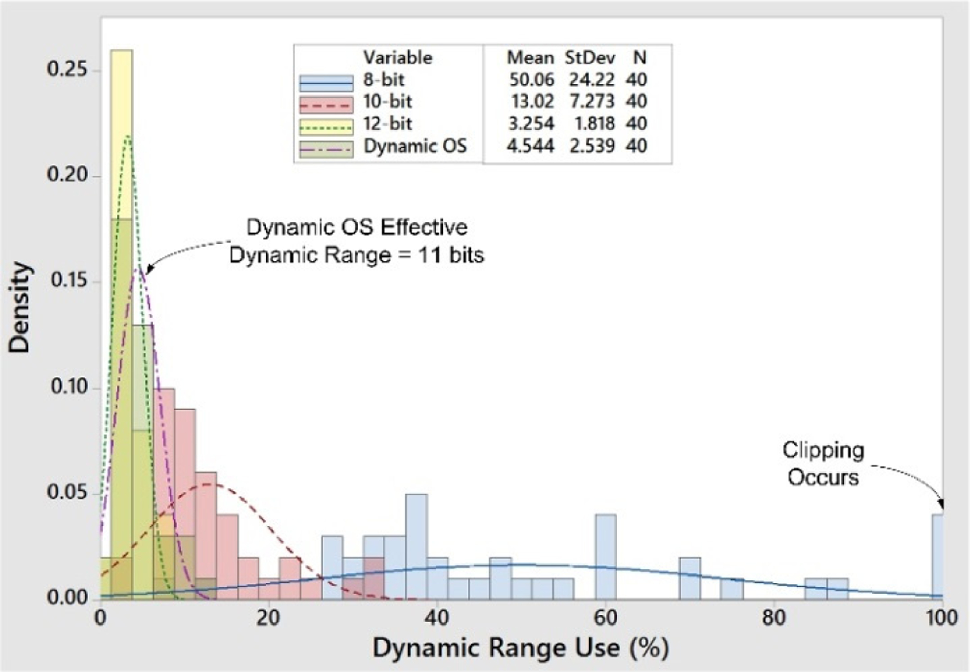
Analysis of human bladder recordings showed that 8-bit instrumentation has insufficient dynamic range to prevent clipping. For these recordings, the proposed dynamic offset approach provided an average 2.9-bits of extra dynamic range. The proposed system effectively boosted the dynamic range of 8-bit instrumentation to 11 bits.
For these representative recordings the use of automatic drift cancellation increased the effective dynamic range by an average of 2.9 bits. Therefore, the system measured pressure approximately at an 11-bit range, while transmitting 28% fewer bits per packet. In a medical implant where the transmission energy/bit is large relative to sensor acquisition, this is an advantageous way to save energy.
IV. Offset Cancellation Bench Test
The offset removal system was combined as part of a wireless bladder pressure sensing ASIC fabricated in OnSemi C5F 0.5-μm (Fig. 6) [9]. The IDAC and digital components of the cancellation system consumed 0.3 mm2.
Fig. 6.
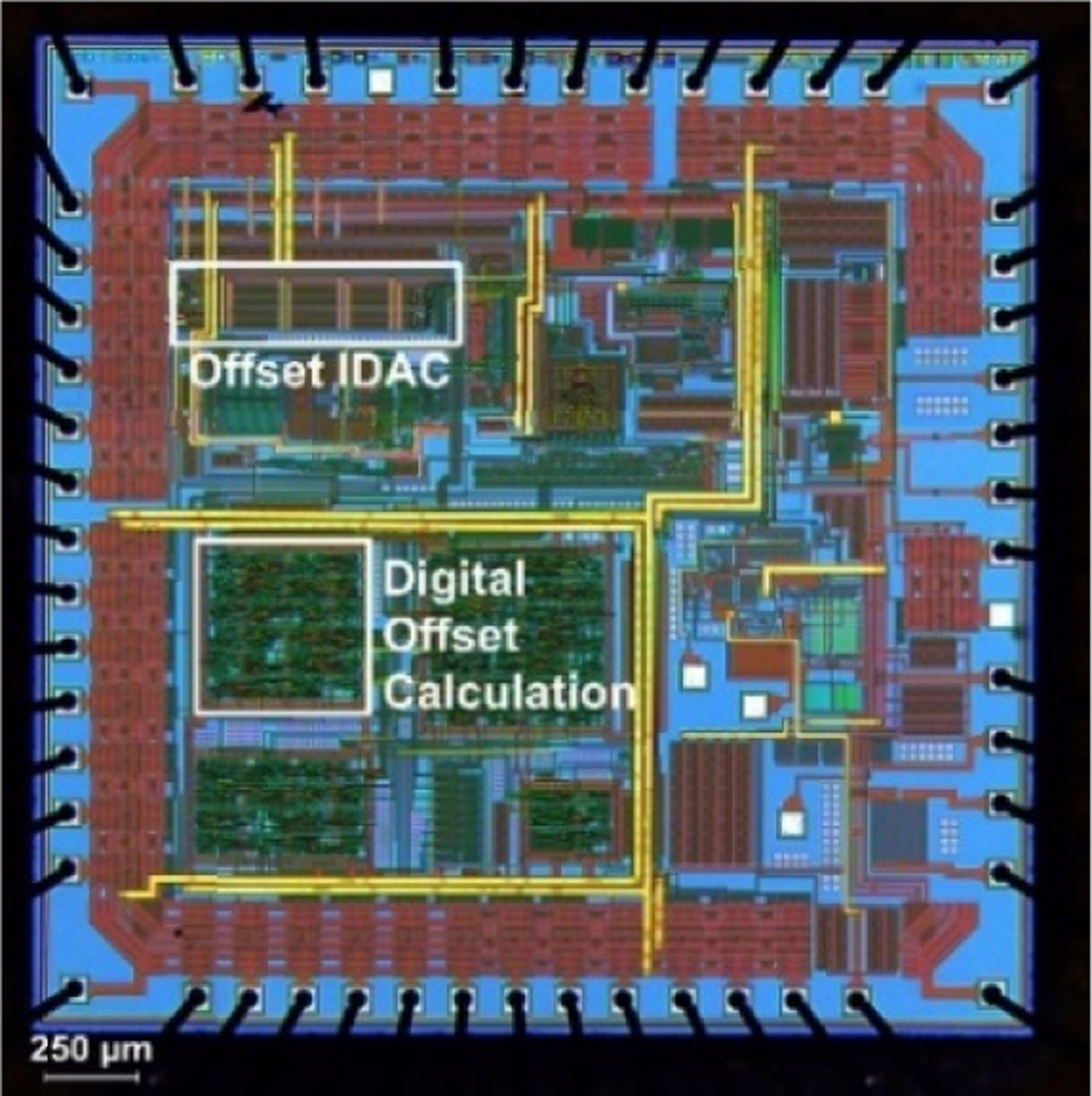
Custom bladder pressure sensor ASIC including the offset cancellation system (highlighted). Drift cancellation circuitry occupied 0.3 mm2.
The automatic offset removal system step response was tested by allowing the system to stabilize for about 10 minutes before applying a step input change of +/− 50 Ω (about +/− 10 mV) across the sensor with a digital potentiometer. This simulated a pressure step response with faster rise time and controllable amplitude than could be obtained in a pressure chamber. Output ADC samples and IDAC codes were wirelessly transmitted by the ASIC to a collection system (Fig. 7).
Fig. 7.
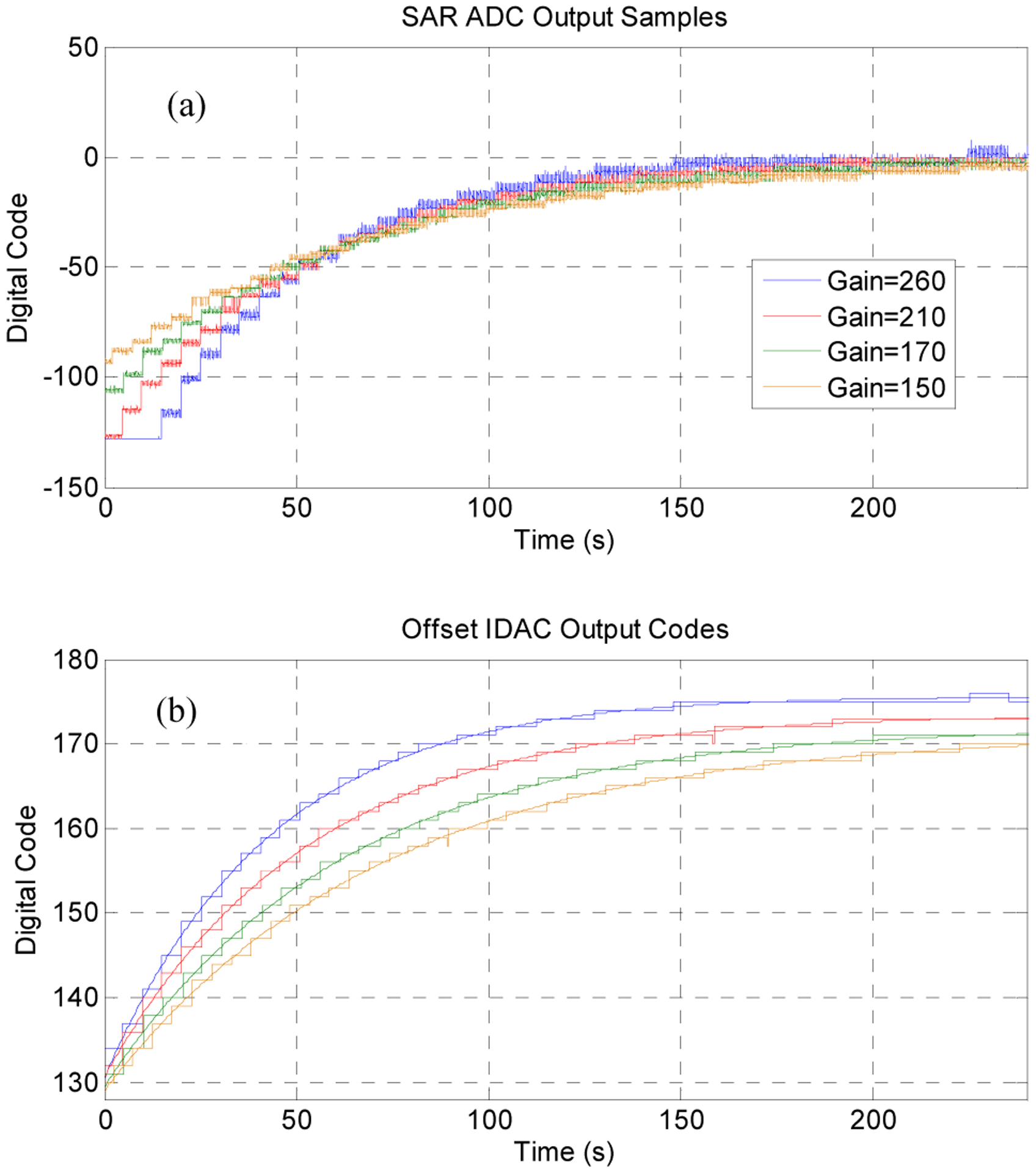
The auto-offset removal system step response at all INA gain settings (a) demonstrated a very long time constant, as designed. Transmitted IDAC values (b) may be used to calculate the absolute DC pressure if desired.
Although the test setup produced a few codes of ADC noise due to digital interference at the INA input, the offset cancellation demonstrated the expected 1st-order settling with time constant τOS close to expected values (Table 2). The system time constant and final IDAC value required to balance the bridge offset was gain dependent, as expected from Eq. (1). The equivalent high-pass corner frequency for the system ranged from 2.3 – 3.8 mHz, which is low enough to permit accurate detection higher-frequency bladder events.
Table 2.
Measured time constants of the automatic offset removal system.
| INA Gain | Estimated τOS (seconds) | Measured τOS (seconds) | Offset system high-pass fC (mHz) |
|---|---|---|---|
| 150 | 68.3 | 70.2 | 2.3 |
| 170 | 60.3 | 62.0 | 2.6 |
| 210 | 48.8 | 51.3 | 3.1 |
| 260 | 45.5 | 42.2 | 3.8 |
V. Conclusion
Chronically implanted pressure sensors suffer from long-term offset drift caused by atmospheric pressure changes, implant location or patient posture shifts, and tissue overgrowth. A mixed-signal dynamic offset cancellation scheme has been designed to maximize the available dynamic range for sensing transient pressure changes in an implanted pressure sensor. Unlike AC-coupled approaches, this method permits sensing of static offsets and is more appropriate for power-gated or RF-powered sensors in which the pressure sensor is only intermittently enabled. Test results of the dynamic offset cancellation with human bladder pressure recordings show that the technique can add 3 bits of effective dynamic range to 8-bit instrumentation. The circuitry was fabricated in 0.5-μm CMOS and demonstrated a controllable, linear frequency response with highpass corner frequency of 2.3 – 3.8 mHz.
Acknowledgment
Human data were collected at the Louis Stokes Cleveland Veterans Affairs Medical Center (IRB #12023-H12).
This work was sponsored by the US Department of Veterans Affairs, Case Western Reserve University, and the Cleveland Clinic
References
- [1].Cleven N et al. , “A novel fully implantable wireless sensor system for monitoring hypertension patients,” IEEE Transactions on Biomedical Engineering, vol. 59, no. 11, pp. 3124–3130, November 2012. [DOI] [PubMed] [Google Scholar]
- [2].Chow E, Chlebowski A, Irazoqui P, “A miniature-impantable RF-wireless active glaucoma intraocular pressure monitor,” IEEE Trans on Bio Circuits and Systems, vol. 4, no. 6, pp. 340–349, December 2010. [DOI] [PubMed] [Google Scholar]
- [3].Coosemans J, Puers R, “An autonomous bladder pressure monitoring system,” Sensors and Actuators A, vol. 123, pp. 151–161, April 2005. [Google Scholar]
- [4].Clowes J et al. , “Low drift fibre optic pressure sensor for oil field downhole monitoring,” Electronics Letters, vol. 35, pp. 926–927, 1999. [Google Scholar]
- [5].Majerus S, Fletter P, Damaser M and Garverick S, “Low-power wireless micromanometer system for acute and chronic bladder-pressure monitoring,” IEEE Trans on Bio Eng, vol. 58, no. 3, pp. 763–768, 2011. [DOI] [PMC free article] [PubMed] [Google Scholar]
- [6].Hyo-Gyuem R et al. “A Fully Self-Contained Logarithmic Closed-Loop Deep Brain Stimulation SoC With Wireless Telemetry and Wireless Power Management,” IEEE Journal of Solid-State Circuits, vol. 49, no. 10, pp. 2213–2227, 2014. [Google Scholar]
- [7].Jongwoo L, Hyo-Gyuem R, Kipke D, Flynn M, “A 64 Channel Programmable Closed-Loop Neurostimulator With 8 Channel Neural Amplifier and Logarithmic ADC,” IEEE Journal of Solid-State Circuits, vol. 45, no. 9, pp. 1935–1945, 2010. [Google Scholar]
- [8].EPCOS, AG, “Pressure Sensors - C29 Series,” 2009. Available: http://www.epcos.com/inf/57/ds/c29_abs.pdf. [28 August 2013].
- [9].Majerus S, Garverick S, “Power management circuits for a 15-μA, implantable pressure sensor,” Cust Integ Circuits Conf, San Diego, 2013. [Google Scholar]


