Significance
We demonstrate by theory and experiments that a liquid crystal–based chiral photonic crystal (CPC), fabricated with a field-assisted molecular self-assembly technique to an unprecedented number (N > 1,000) of unit cells, will achieve the full potentials of an ideal (N → ∞) CPC. Such high-N CPCs possess large optical rotatory power with near-unity transmission, work equally well on lasers of simple or complex vector fields, and allow dynamic polarization switching and control by virtue of field-induced index/birefringence changing mechanisms at modest or ultrafast speeds. They are highly promising alternatives to current state-of-the-art polarization manipulation optics that exhibit giant optical rotatory power but are generally passive and beset with large optical loss.
Keywords: polarization rotation, chiral photonic crystal, liquid crystal, laser vector field
Abstract
State-of-the-art nanostructured chiral photonic crystals (CPCs), metamaterials, and metasurfaces have shown giant optical rotatory power but are generally passive and beset with large optical losses and with inadequate performance due to limited size/interaction length and narrow operation bandwidth. In this work, we demonstrate by detailed theoretical modeling and experiments that a fully developed CPC, one for which the number of unit cells N is high enough that it acquires the full potentials of an ideal (N → ∞) crystal, will overcome the aforementioned limitations, leading to a new generation of versatile high-performance polarization manipulation optics. Such high-N CPCs are realized by field-assisted self-assembly of cholesteric liquid crystals to unprecedented thicknesses not possible with any other means. Characterization studies show that high-N CPCs exhibit broad transmission maxima accompanied by giant rotatory power, thereby enabling large (>π) polarization rotation with near-unity transmission over a large operation bandwidth. Polarization rotation is demonstrated to be independent of input polarization orientation and applies equally well on continuous-wave or ultrafast (picosecond to femtosecond) pulsed lasers of simple or complex (radial, azimuthal) vector fields. Liquid crystal–based CPCs also allow very wide tuning of the operation spectral range and dynamic polarization switching and control possibilities by virtue of several stimuli-induced index or birefringence changing mechanisms.
Optical vector field (more commonly called polarization) rotators and switches are essential components of all modern optical and photonic systems for communications, ellipsometry, metrology, biological/chemical detection, and quantum processing/computing (1–10). There are, however, some inherent limitations. Wave plates made with birefringent crystals, for example, require strict alignment of the optic axis with respect to the polarization orientation of incident light and generally do not work with laser vector beams of complex polarization fields; Faraday rotators that do not have this requirement are generally too cumbersome and bulky due to their weak optical rotatory powers. One promising approach to circumvent these limitations is to employ chiral optical materials such as chiral photonic crystals and metasurfaces. Nevertheless, structural chirality, such as chiral metamaterials, metasurfaces, and photonic crystals that are capable of very large optical rotatory power (up to ∼100,000°/mm), are inevitably accompanied by large absorption losses (11–15). In metamaterials/surfaces, the intrinsic noncircular absorption and nanofabrication difficulty also add to the limitation of their practical scalability in the interaction length, resulting in small (<π) net polarization rotation angle, very small aperture, and narrow operating spectral bandwidth (11–13). Similar issues confront most chiral photonic crystals (CPCs) due to the limitations of molecular self-assembly or nanofabrication/processing technique and high transmission loss associated with operation near the Bragg reflection band (14, 15).
Here, we show by theory and experimental corroborations that a fully developed liquid crystal–based CPC, one for which the number of unit cells N approaches that (N → ∞) of an ideal crystal, can circumvent all the aforementioned limitations and possess several advantageous characteristics impossible with conventional low-N thin counterparts. Such high-period–number chiral photonic crystals (HN-CPCs) are achieved by fabricating cholesteric liquid crystals (CLCs) to thicknesses several hundred times that of conventional ones using a refined field-assisted self-assembly (FASA) technique (16, 17; see SI Appendix, Note 1, for more details). Optical properties of CLCs as CPCs arise from complex “collective” responses from many unit cells. While thicker crystals obviously give rise to larger effects, the resulting properties as the crystal thickness or period number N evolves from low values to a very high value do not lend themselves to such simple linear extrapolation; as a function of N, pleasant surprises and new insights and possibilities abound. Our studies show that for N > 500, these CLCs exhibit simultaneously broad transmission maxima and large polarization rotation power in the off-Bragg-resonance spectral regime. Polarization rotation is independent of input polarization orientation and acts equally well on simple or complex vector fields (18–22) of continuous-wave (CW) or ultrafast pulsed laser beams. Liquid crystal–based CPCs also allow dynamic polarization switching and control by virtue of field–induced index/birefringence changing mechanisms at modest or ultrafast (picosecond to femtosecond) speeds (23–34).
CPC Properties of CLCs Revisited
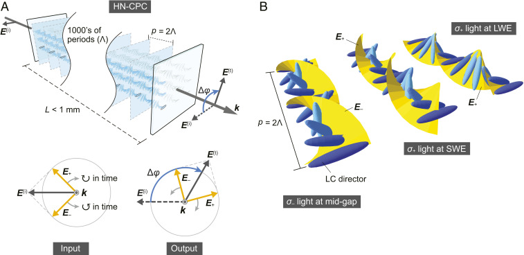
In a CLC, the birefringent optic axes naturally self-assemble in a helical manner (Fig. 1A). Along the helix, a circularly polarized probe of the same handedness as the CLC “sees” a sinusoidal Bragg grating, whereas its opposite-hand counterpart sees a uniform medium with an averaged refractive index navg ∼ (ne + no)/2 (Fig. 1B), where ne is the extraordinary index and no is the ordinary index. Optical rotation is enabled by the circular birefringence Δnc—the index difference experienced by left (σ−) and right (σ+) circular polarizations [Δnc = n− − n+]. Since any polarization can be seen as a coherent superposition of the circular eigenpolarizations, their phase retardation (Γ) accumulated during propagation produces a rotation of the polarization vector by an angle Δφ = Γ/2 = ΔncπL/λ0 (Fig. 1A), where L is the interaction length and λ0 is the optical wavelength in vacuum. Δφ is, in general, independent of the input vector orientation. Multiple local reflections occur in the medium if the wavelength of the same-hand probe is comparable to the helical pitch (p, twice the grating period Λ), giving rise to interference of the forward and backward propagating waves and resulting in a photonic bandgap (PBG) and strong band-edge dispersions typical of a CPC.
Fig. 1.
(A) Schematic of an HN-CPC as a chiroptical rotator. Δφ: optical rotation angle, L: thickness, p: helical pitch, Λ: grating period, E(i)/(t): incident (input) and transmitted (output) linear polarizations, E+/−: right circular (σ+) and left circular (σ−) polarizations, k: wavevector of light, ↻: clockwise, ↺: counterclockwise. (B) Orientational relationships between optical electric field and LC director under three different conditions: left circular polarization at the mid-gap (Left), right circular polarization at short-wavelength edge (SWE) (Middle), right circular polarization at long-wavelength edge (LWE) (Right).
Following standard treatment, a (say, right-handed) CLC is divided into N/2 lamellae; each lamella comprises a complete helicoidal twist of LC director with a thickness given by the pitch p = 2Λ. The coupled equations of the forward-propagating [transmitted; denoted by superscript (f)] and backward-propagating [reflected; denoted by superscript (b)] σ+-polarized waves at the jth and (j+1)th lamellar interfaces can be rewritten as (35, 36)
| [1] |
where δ is the accumulated optical phase per lamella without the chiral Bragg resonance (CBR) in effect, −iQ ∼−i[π(ne − no)/navg]sin(ε)/ε is the reflection coefficient per lamella, and ε = δ − 2π = 2π(λmid – λ0)/λ0 describes the phase difference (per lamella) between the lights at the operating wavelength (λ0) and midgap wavelength (λmid). From Eq. 1, the accumulated σ+ phase throughout the CLC can be deduced (detailed in SI Appendix, Note 2). From the total phase retardation Γ (= 2πLΔnc/λ0 as mentioned earlier) and the polarization rotation angle Δφ, the optical rotatory power (ORP) can be derived:
| [2] |
where
| [3] |
and m = 0, 1, 2, … (SI Appendix, Note 2). For practical implementation, a polarization rotation Δφ = ORP⋅N⋅Λ of at least π with near-unity transmission is needed. In CPCs, the primary loss mechanism is the Bragg reflection of circularly polarized light near the PBG, characterized by the σ+ reflectivity
| [4] |
and R+ = 1 within the PBG (SI Appendix, Notes 2 and 3). The total transmission is therefore given by: Ttot = 1 − 1/2R+, and the polarized transmission Tpol is given by
| [5] |
Here, Δφ is the polarization rotation by the CLC and φA is the angle made by the transmission axis of the analyzer with the input polarization. We also define a polarization figure of merit, PFM, to characterize the degree of polarization contrast of the output from the analyzer:
| [6] |
where Tmax and Tmin are the measured maximum and minimum values of Tpol.
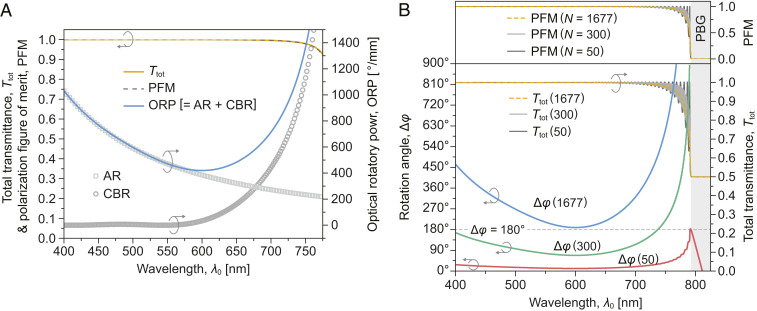
Eqs. 2–6 form the basis of our theoretical simulations of various optical properties of CLCs as N is increased from low to very high value. Fig. 2 shows exemplary plots of the transmission Ttot, PFM, ORP, and Δφ as functions of the detuning from the band edge. A unique advantage of an HN-CPC is that it can produce large polarization rotation Δφ with near-unity Ttot and PFM at detuning beginning from ∼50 nm to several hundred nanometers from the band-edge, in stark contrast to the low-N CPC, which generally yields much smaller Δφ of ≪π (Fig. 2B). These and other extraordinary characteristics of HN-CLC are borne out in detailed comparison between experiment results and theoretical simulations in the following sections.
Fig. 2.
(A) Total (unpolarized) transmission Ttot, polarization figure of merit (PFM), and ORP as functions of wavelength in the vicinity and far off the photonic band-edge of CPC. Parameters: Λ = 268.4 nm, ne = 1.5358 + 7,329.8/λ02, no = 1.4655 + 5,359.1/λ02, and λSWE ∼ 790 nm. (B) Comparative plots of polarization rotation angle (Δφ), Ttot, and PFM of typical conventional low-N (n = 50 and 300) and high-N (n = 1,677, experimental value) CPCs.
From these and other simulations (see SI Appendix, Note 2 for more details), one could conclude that the overall response of the CLC for n > 500 is to all intents and purposes equivalent to the limiting case of N → ∞, when Eq. 2 becomes (35)
| [7] |
It is clear from Eq. 7 that the overall ORP is ultimately determined by the material birefringence [Δn = ne − no] which appears in the first term and in the second term through the dependency of Q on Δn.
Cell Fabrication and Characterizations
Conventional thin CLCs are fabricated using molecular self-assembly and rely on the surface anchoring forces to align the helical axis perpendicular to the cell window. This process works for sample thicknesses up to about tens of microns, but for thick (>100 μm) cells, molecular self-assembly alone tends to produce randomly aligned defects (oily streaks) and highly scattering focal conics as the surface anchoring forces become too weak to influence the bulk; these oily streaks and other highly scattering defects (SI Appendix, Fig. S1) could be partially eliminated by a strong applied field, but they returned when the applied field is removed.
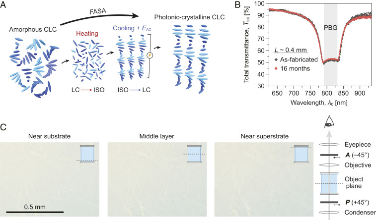
The strategy of the FASA technique (16, 17) is to prevent the impossible-to-remove oily streaks and defects from ever forming in the first place. The procedure is to begin applying a strong electric field [from an alternating-current (AC) voltage source] when the CLC mixture is still in the isotropic phase; the applied field is continuously maintained during the molecular self-assembly process when the sample cools down to below the transition temperature and long (∼3 h) after the self-assembly process was completed, as schematically depicted in Fig. 3A (see also Movie S1). Here, we present a summary of all pertinent information for fabricating stable, well-aligned HN-CLC with thicknesses in the range of several hundreds of microns (N ∼ 1,300 to over 3,000). The starting CLC is prepared by mixing a dielectrically negative nematogen [Δε (= ε∥ − ε⊥) < 0] with a trace amount (1–2 wt%) of chiral agent (SI Appendix, Note 1). The grating period is controlled by modifying the mixing ratio, Λ ∼(2βw)−1, where β and w are the twisting power and mass fraction of the chiral agent, respectively.
Fig. 3.
(A) Schematic of FASA process. (B) Total transmission (Ttot) spectra of a 0.4 mm–thick sample captured just after fabrication and 16 mo later, showing long-term stability. (C) Polarized microscope images of a 0.3 mm–thick sample at different object planes.
The sample (cell with a CLC mixture) is first heated to 10 to 30 °C above the clearing point (∼80 °C) to completely randomize molecular orientations and then allowed to cool down to the final (room) temperature during which the sample underwent molecular self-assembly. An AC field is applied across the cell windows throughout the cooling period and maintained for another 3 h at room temperature to ensure that the molecular assembly reaches the steady state. Detailed characterization studies that include measurements of the photonic-crystal properties and polarized microscope images of the texture at different planes inside the approximately millimeter-thick CLCs have shown that such HN-CLCs fabricated with the FASA technique are very stable and retain their optical clarity and CPC properties over a long time (more than two years now since they are fabricated) (Fig. 3 B and C; see also SI Appendix, Fig. S2, for more photos and micrographs). Such stability and robustness are also borne out by the consistent reproducibility of the experimental data/results on polarization rotation measurements detailed in the following sections.
Experimental Verification of Large Polarization Rotation and High Transmission
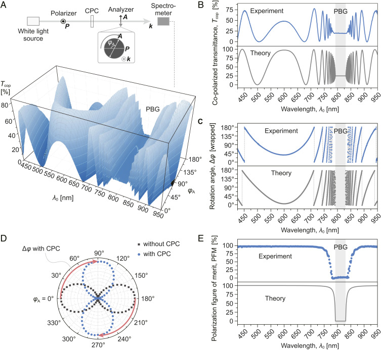
Fig. 4A shows the experimental setup and the measured polarized transmission spectrum as the analyzer is rotated by an angle φA relative to the input linear polarizer. From these data, the spectral dependencies of Tpol, PFM, Δφ, and other characteristics are extracted and compared with theoretical predictions. Substantial oscillations in the polarized transmission spectrum are indicative of very large optical polarization rotation by the HN-CPC. To fit the experimental data, we first estimate the Λ from the concentration and twisting power of the chiral agent in the nematic host and estimate N from the cell thickness L (= NΛ). The extended Cauchy model (37) is applied to describe the optical dispersions of ne and no, in which the coefficients are obtained by fitting the refractive indices of the host LC measured at three wavelengths by an Abbe refractometer. Since the sample thickness is in the high-N regime (n > ∼500), it is deemed well developed, allowing us to use Eqs. 4, 5, and 7 to fit the measured copolarized transmission spectrum (Tcop, which is Tpol at φA = 0°); very good agreement is obtained with the parameters ne = 1.5358 + 7,329.8/λ02, no = 1.4655 + 5,359.1/λ02, Λ = 268.4 nm, and L = 0.45 mm (equivalent to n = 1,677) (Fig. 4B).
Fig. 4.
(A) Experimental setup and polarized transmission spectrum as a function of analyzer angle φA of a 0.45 mm–thick sample. (B) Measured and theoretical copolarized transmission (Tcop) spectra exhibiting substantial oscillations. (C) Spectrally resolved wrapped rotation angle (Δφ) of incident linear polarization: theory and experiment. All data points are constrained to the interval (0, π) (i.e., wrapped angle equals to total rotation angle modulo 180°). (D) Polar plots of polarized transmission captured without and with the HN-CPC sample. (E) Spectral dependence of polarization figure of merit (PFM): theory and experiment.
The spectrally resolved rotation angle Δφ (Fig. 4C) can be extracted by applying Δφ = cos−1[(Tpol − Tmin)1/2/(Tmax − Tmin)1/2] − φA, where Tmax and Tmin are the maximum and minimum transmittances measured at each wavelength. Near the PBG, where the chiral Bragg resonant effect is intense, the rotation angle Δφ varies sharply with wavelength λ0; at ∼10 nm away from the short-wavelength edge (SWE), the total rotation angle is ∼1,350°, and the variation rate [d(Δφ)/dλ0] is >100°/nm. At larger detuning, the total rotation angle becomes smaller but is still very large; the smallest rotation angle in the entire spectrum below the SWE occurs at λ0 ∼600 nm (a detuning of ∼200 nm) is ∼217°. Consistent with the theoretical prediction (Fig. 3B), the minimally dispersive regime occurs at which the CBR dispersion is compensated by the AR dispersion. The rotation angle and variation rate increase again for shorter wavelength as the AR begins to dominate the rotatory dispersion.
From the polarized transmission spectra (Fig. 4A), one can plot out the polar pattern of the rotation angle (Fig. 4D) experienced by the incident light at each wavelength through the HN-CLC and compare it with the case without the CLC. The CLC causes a clockwise rotation of an incident linear polarization from horizontal to almost vertical (88°); the actual total rotation of the polarization in the CPC is found to be 268° (= 88° + π)] by theoretical fitting with Eq. 7. The polar pattern also reveals a large contrast between the maximal and minimal transmittances (Tmax and Tmin), with a measured PFM ∼ 99.4%). Fig. 4E shows the PFM spectrum obtained by taking the difference between the Tmax and Tmin measured at each wavelength (from Fig. 4A) and normalized the difference by their sum (Tmax + Tmin) (Eq. 6). The PFM rises steeply from ∼0% at the band-edge to almost 100% when λ0 is 60 nm away from the photonic band edges; the corresponding total rotation angle is very large (∼430°). The well-preserved degree of linear polarization even upon large rotation is attributed to the ultrawide operation spectrum (hundreds of nanometers) away from the PBG of HN-CPCs, where the total transmittance Ttot is maximized as the Bragg reflectivity R+ is negligible (also evident in Fig. 4B).
Polarization Rotation of Complex Vector Fields of CW and Femtosecond-Pulsed Lasers
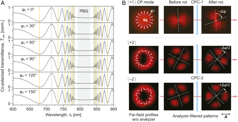
One of the main advantages of CPCs over conventional waveplates is that the polarization rotation process is generally independent of the incident polarization angle (φ0) with respect to the azimuthal orientation of the helices, and therefore it works well with simple (linear or elliptical) or complex (radial, azimuthal, etc.) vector fields of lasers. Fig. 5A shows the copolarized transmission spectra of a linearly polarized light at different incident polarization angles φ0; the spectra exhibit extrema (peaks and valleys) corresponding to wrapped rotation angle Δφ of 0° and 90°, respectively. The vertical solid and dashed lines connecting respective local extrema clearly shows perfect matching of the polarization rotation Δφ(λ0) for different incident polarization orientations φ0 [i.e., Δφ(λ0) is independent of φ0, and therefore, HN-CPC should be able to simultaneously rotate (by the same angle) all the local polarizations of more complex vector fields, such as briefly demonstrated previously (17) with a CW laser exhibiting cylindrical polarization (CP) mode |l⟩ = |–2⟩ (22)]. Further confirmations are obtained by examining the pattern rotations of |+1⟩ and |+2⟩ cylindrically polarized lasers with two HN-CPC samples, CPC-1 (Δφ = 72° at 633 nm) and CPC-2 (Δφ = 49° at 633 nm) (Fig. 5B). The analyzer-filtered |+1⟩ pattern exhibits two lobes, while the |+2⟩ and |–2⟩ patterns exhibit four lobes. With the CPC-1 inserted in the path of the probe beam, the |+1⟩ pattern is preserved and rotated by 72° clockwise when viewed along the propagation direction of light, which is the same angle as the polarization rotation by CPC-1 but in the opposite direction. With the CPC-2 inserted in the |+2⟩ beam path, the four-lobed pattern is also preserved but rotated by ∼25° clockwise. Using similar theoretical fitting with Eqs. 5 and 7, we deduce that all the transverse vectors are rotated counterclockwise by the same angle, and the rotation angle of the analyzer-filtered pattern is [−Δφ/l] for cylindrically polarized light.
Fig. 5.
(A) Copolarized transmission spectra of HN-CPC (N ∼ 1,600) showing that the optical rotation is independent of incident polarization orientation (φ0). (B) Simultaneous rotation of all transverse vectors in beams with different cylindrical polarization modes. White arrows: input vector distributions. Dotted lines indicate the dark-region orientation of the analyzer-filtered pattern before polarization rotation; Dashed lines indicate the dark-region orientation of the analyzer-filtered pattern after polarization rotation. Transmission axis of the analyzer is indicated by A.
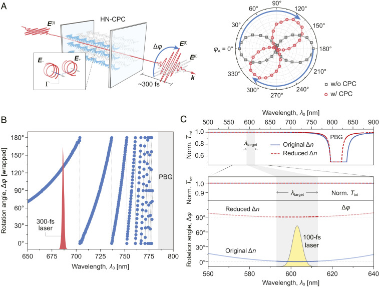
HN-CPCs can also be used to rotate the polarization of short (picosecond, femtosecond) laser pulses. In the experiment shown in Fig. 6A, horizontally polarized 300-fs pulses at 686.2 nm are sent through a 0.44 mm–thick CPC (N ∼ 1,600) characterized by the following parameters: Λ ∼ 265.8 nm, λmid ∼ 803 nm, and λSWE ∼ 784 nm. Experimental results depicted in the polar plots of Fig. 6A show that the horizontally polarized input laser pulse is rotated clockwise by ∼130°; this is in good agreement with the expectation (129.6°) from the Δφ spectrum measured at this wavelength (Fig. 6B). The PFM values obtained from the polar plots for the input (99.9%) and the output (97.7%) also demonstrate very good preservation of the degree of linear polarization after passage through such a thick CLC (HN-CPC). Nevertheless, it is important to note here that all wavelength components of the 300-fs laser experience the same polarization rotation angles with the same near-unity Ttot and PFM values simply because of its relatively narrow bandwidth (∼2.4 nm). This would not be the case if the pulse duration is much shorter, (e.g., a 100 fs laser with much broader bandwidth). (Note: the minimum transform-limited bandwidth of a 100-fs pulse is ∼5.4 nm.) In that case, polarization rotation should be conducted in the spectral region where the variation in Δφ is practically “flat,” as depicted in Fig. 6C (blue solid curve); within a spectral range of nearly 20 nm (much broader than the laser bandwidth), all wavelength components of the laser would experience the same polarization rotation angle with near-unity Ttot and PFM. In Fig. 6C, we have also plotted the spectral dependence of the rotation angle if the birefringence Δn of CLC is changed by −0.0227, showing the resulting 0° to 90° polarization rotation/switching of all wavelength components within the laser bandwidth.
Fig. 6.
(A) Schematic of polarization rotation of 300-fs laser pulse by HN-CPC (Left). Polar plots of polarized transmittance measured with and without the CPC of 300-fs laser pulses (Right). (B) Spectrally resolved wrapped rotation angle (Δφ) of incident linear polarization obtained with continuous-wave white light source. Sample parameters (obtained through curve fitting): ne = 1.5358 + 7,329.8/λ02, no = 1.4655 + 5,359.1/λ02, Λ = 265.8 nm, and L ∼ 0.435 mm (equivalent to N ∼ 1,636). Spectrum of the ultrafast laser shown in red is for viewing purposes only, not plotted to scale. (C) Theoretical simulation of the spectral dependence of the polarization rotation (blue solid curve) with similar CLC parameters to those used in B. Red dashed curves are also plotted for the case in which the birefringence Δn of CLC is changed by −0.0227. Laser spectrum corresponds to a transform-limited Gaussian pulse of 100 fs, bandwidth ∼ 5.4 nm. (Upper) Normalized total transmission (norm. Ttot) spectrum showing the change of PBG by Δn modulation. (Lower) Close-up norm. Ttot and Δφ spectra in the targeted operation range.
Tuning and Reconfiguration of the HN-CPC and Polarization Switching
LC-based photonic crystals, whether in 1D (CLC) or 3D (blue-phase liquid crystals), are well known for tunability owing to the availability of a large assortment of liquid crystals with specially designed physical properties to suit application throughout a very wide spectral regime from visible to near infrared. The wavelength locations of photonic bandgap and band-edges and the dispersion characteristics and related optical properties of CLCs (e.g., spectral dependence of polarization rotation) can all be tailored-made through synthesis or electrically tuned by virtue of the easy susceptibilities of the LC constituents to external stimuli (23–34).
In the case of CLCs, direct tuning of the grating period (or, pitch) can be realized by electrically induced helix deformation or by incorporating photoisomeric constituents in the CLC (25, 26); other means of changing the order parameter (e.g., by changing the temperature), thereby changing the refractive indices or birefringence, could also be employed to tune the CLC characteristics. Grating period modulation can also be accomplished without lattice distortion. According to the Bragg’s law, the grating period experienced by light is related to the angle of incidence θ (measured from normal) by Λ = ΛNcosθ, where ΛN is the grating period as seen by the light incident at normal. Reorienting the grating vector by tilting the helical axis will thus alter Λ. For the exemplary HN-CPC and the experimental condition mentioned above, the required tilt of the helices to enable 90° switching is ∼15 to 20°. Such helix tilting can be achieved mechanically, photomechanically, or through electrically induced undulation instability (27, 28).
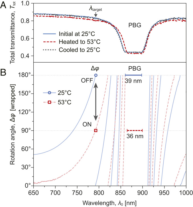
These mechanisms for tuning CLC properties and dynamic control/switching of the polarization state of the transmitted light through CLCs are characterized by a wide range of response times. Manual or automated mechanical tilting of the sample orientation clearly take (many) seconds but may be a required procedure in the initial optical setup with the HN-CLC in place. Others that involve distortion of the lattice spacing to tune the photonic bandgap are also quite slow with response times ranging from seconds to milliseconds. As a feasibility demonstration of polarization switching with HN-CLCs, we conducted an experiment in which the birefringence change (which causes an order parameter modification) and slight elongation of the grating period are produced by heating. Using a setup and procedure like the one that yields experimental results reported in Figs. 4–6, we have measured spectral dependence of the transmittance and polarization rotation angles of a linearly polarized probe light (from 650 nm to 1,000 nm) by a 0.3 mm–thick CLC (N ∼ 1,000, Λ ∼ 292 nm, and Δn = ne − no ∼ 0.07 at 25 °C) as a function of temperature. As depicted in Fig. 7A, when temperature is raised from 25 °C to 53 °C, the width of the photonic bandgap is shrunken from ∼39 nm to ∼36 nm because of a drop in birefringence Δn, and the band-edges (more so the operation short-wavelength side) are both red-shifted because of a slightly elongated grating period Λ (originating from the weakened twisting power of R5011 at high temperature (38) (Fig. 7A; see SI Appendix, Note 1, for experimental details). These changes in the bandgaps and band-edges give rise to large changes in the spectral dependance of the polarization rotation angles, as shown in Fig. 7B. At the probe wavelength λ = 793 nm, the horizontally (180°, or 0°) polarized output probe light experiences a 90° switching to the vertical (90°) state. When the sample is cooled down to the initial temperature, the polarization is observed to revert to its original (180°) direction.
Fig. 7.
Experimental switching results obtained by changing the order parameter through heating of a 0.3 mm–thick CLC. (A) Measured spectral dependence of the total transmittance through the CLC showing photonic bandgap and band-edge shifts at initial (solid blue and dotted black curves) and elevated (dashed red curve) temperatures. (B) Measured spectral dependence of the polarization rotation angles at the initial temperature of 25 °C (solid blue curve) and the corresponding values at elevated temperature 53 °C (dashed red curve); circle and square dots at λ0 = 793 nm show a 90° rotation of the probe beam polarization.
In this experiment, the temperature of the HN-CPC sample is controlled by a heating stage, but a more compact setup could be realized by exploiting the dielectric heating of LC with an electric field at a frequency that corresponds to a dielectric absorption peak (39). While the demonstrated switching process is slow, it nevertheless illustrates how the birefringence or refractive indices of the HN-CLC can be modulated to enable polarization switching.
We close this section with a note on the possibility of very fast, though transient, polarization switching with ultrafast (picosecond to femtosecond) laser pulse–induced perturbation of the CLC molecules’ electronic wave functions (31–34). Such interaction gives rise to, among other nonlinear optical responses, an intensity-dependent refractive index of the form ne/o = ne/o(0) + n2e/2oI, where ne/o(0) is the unperturbed index value [ne or no], n2e/2o is the corresponding nonlinear index coefficient, and I is the intensity of the laser. Typical LC molecules in CLCs possess a nonresonant n2e [≫n2o] value on the order of 10−13 cm2/W in magnitude; near the photonic band-edges (i.e., in the vicinity of the circular Bragg resonance), the increased optical density of states gives rise to a large enhancement, and n2e of CLC can be as large as ∼10−10 cm2/W. Therefore, a pump laser (wavelength tuned to the band-edge) of modest peak intensity on the order of a few 100 MW/cm2 could produce sufficient index change to shift the photonic bandgap and band-edges and therefore switch the polarization state of a probe laser, cf. simulation presented in Fig. 6C. This is corroborated in a recent experimental observation (33); using a femtosecond pulsed laser to create the index change and photonic band-gap shift in a 9 μm–thick CLC, the polarization state of a femtosecond probe pulse is switched between linear and circular polarizations, and its transmission through a q-plate is switched between a vortex field and a vector field. Although the exact working of such polarization switching in ref. 33 (where the probe wavelength is initially situated near the band-edge and the initial transmission is small) is different from the present case (where the probe wavelength is further away from the band-edge and the transmission is near unity), they utilize the same underlying mechanism of ultrafast laser–induced index change. Nevertheless, an inherent drawback of such ultrafast polarization switching schemes is the requirement of two sophisticated ultrafast (pump and probe) laser systems working in synchrony and the transient nature of the on–off switching following the pump-pulse temporal profile. It is therefore more suited for very fast on–off type of switching applications in advanced photonic switching platforms/systems rather than in conventional or everyday kind of settings that usually need longer hold in the on-state.
Conclusion
Theoretical and experimental studies of fully developed CPCs—realized by field-assisted self-assembly of CLCs to thicknesses several hundred times their conventional counterparts, exhibiting many broad transmission maxima in the off–Bragg-resonance regime, and capable of large polarization rotation with near-unity transmission—have been carried out. Polarization rotation by such an HN-CPC is independent of the orientation of the input polarization, and the degree of linear polarization is well preserved owing to the high transmission far from the photonic band gap. HN-CPCs work well with continuous-wave as well as femtosecond pulsed lasers of simple (linear, elliptical) or complex (radial, high-order cylindrical, etc.) vector fields. Results obtained here will provide guidelines to identify optical parameters and exploit the unique attributes of their liquid crystal constituents for optimal performance of HN-CPC as polarization manipulators and switches.
Supplementary Material
Acknowledgments
We acknowledge the financial support from Wright Patterson Air Force Research Laboratory; the use of the femtosecond laser system of Prof. Xingjie Ni and technical collaboration with Dr. Xuexue Guo; the chiral agent and linear-to-radial polarization converter from Prof. Tsung-Hsien Lin and technical collaboration with Ting-Mao Feng; and helpful discussions with Dr. Timothy J. Bunning, Prof. Jieh-Wen Tsung, and Cheng-Yu Wang.
Footnotes
The authors declare no competing interest.
This article is a PNAS Direct Submission. A.B. is a guest editor invited by the Editorial Board.
This article contains supporting information online at https://www.pnas.org/lookup/suppl/doi:10.1073/pnas.2021304118/-/DCSupplemental.
Data Availability
All study data are included in the article and/or supporting information.
References
- 1.Wang H., et al., In vitro and in vivo two-photon luminescence imaging of single gold nanorods. Proc. Natl. Acad. Sci. U.S.A. 102, 15752–15756 (2005). [DOI] [PMC free article] [PubMed] [Google Scholar]
- 2.Rhee H., et al., Femtosecond characterization of vibrational optical activity of chiral molecules. Nature 458, 310–313 (2009). [DOI] [PubMed] [Google Scholar]
- 3.Vrabioiu A. M., Mitchison T. J., Structural insights into yeast septin organization from polarized fluorescence microscopy. Nature 443, 466–469 (2006). [DOI] [PubMed] [Google Scholar]
- 4.Campagnola P. J., Loew L. M., Second-harmonic imaging microscopy for visualizing biomolecular arrays in cells, tissues and organisms. Nat. Biotechnol. 21, 1356–1360 (2003). [DOI] [PubMed] [Google Scholar]
- 5.Zhanghao K., et al., Super-resolution imaging of fluorescent dipoles via polarized structured illumination microscopy. Nat. Commun. 10, 4694 (2019). [DOI] [PMC free article] [PubMed] [Google Scholar]
- 6.Wang G., Sun W., Luo Y., Fang N., Resolving rotational motions of nano-objects in engineered environments and live cells with gold nanorods and differential interference contrast microscopy. J. Am. Chem. Soc. 132, 16417–16422 (2010). [DOI] [PubMed] [Google Scholar]
- 7.Larocque H., et al., Reconstructing the topology of optical polarization knots. Nat. Phys. 14, 1079–1082 (2018). [Google Scholar]
- 8.Parigi V., et al., Storage and retrieval of vector beams of light in a multiple-degree-of-freedom quantum memory. Nat. Commun. 6, 7706 (2015). [DOI] [PMC free article] [PubMed] [Google Scholar]
- 9.Bouwmeester D., et al., Experimental quantum teleportation. Nature 390, 575–579 (1997). [Google Scholar]
- 10.Walther P., et al., Experimental one-way quantum computing. Nature 434, 169–176 (2005). [DOI] [PubMed] [Google Scholar]
- 11.Hodgkinson I., Wu Q. H., Knight B., Lakhtakia A., Robbie K., Vacuum deposition of chiral sculptured thin films with high optical activity. Appl. Opt. 39, 642–649 (2000). [DOI] [PubMed] [Google Scholar]
- 12.Kuwata-Gonokami M., et al., Giant optical activity in quasi-two-dimensional planar nanostructures. Phys. Rev. Lett. 95, 227401 (2005). [DOI] [PubMed] [Google Scholar]
- 13.Zhu A. Y., et al., Giant intrinsic chiro-optical activity in planar dielectric nanostructures. Light Sci. Appl. 7, 17158 (2018). [DOI] [PMC free article] [PubMed] [Google Scholar]
- 14.Takahashi S., et al., Giant optical rotation in a three-dimensional semiconductor chiral photonic crystal. Opt. Express 21, 29905–29913 (2013). [DOI] [PubMed] [Google Scholar]
- 15.Turner M. D., et al., Miniature chiral beamsplitter based on gyroid photonic crystals. Nat. Photonics 7, 801–805 (2013). [Google Scholar]
- 16.Chen C.-W., Guo X., Ni X., Lin T.-H., Khoo I. C., Slowing sub-picosecond laser pulses with 0.55 mm-thick cholesteric liquid crystal. Opt. Mater. Express 7, 2005–2011 (2017). [Google Scholar]
- 17.Chen C.-W., Khoo I. C., Extraordinary polarization rotation of vector beams with high-period-number chiral photonic crystals. Opt. Lett. 44, 5306–5309 (2019). [DOI] [PubMed] [Google Scholar]
- 18.Willner A. E., Vector-mode multiplexing brings an additional approach for capacity growth in optical fibers. Light Sci. Appl. 7, 18002 (2018). [DOI] [PMC free article] [PubMed] [Google Scholar]
- 19.Wang J., et al., Terabit free-space data transmission employing orbital angular momentum multiplexing. Nat. Photonics 6, 488–496 (2012). [Google Scholar]
- 20.Naidoo D., et al., Controlled generation of higher-order Poincaré sphere beams from a laser. Nat. Photonics 10, 327–332 (2016). [Google Scholar]
- 21.Milione G., Sztul H. I., Nolan D. A., Alfano R. R., Higher-order Poincaré sphere, Stokes parameters, and the angular momentum of light. Phys. Rev. Lett. 107, 053601 (2011). [DOI] [PubMed] [Google Scholar]
- 22.Holleczek A., Aiello A., Gabriel C., Marquardt C., Leuchs G., Classical and quantum properties of cylindrically polarized states of light. Opt. Express 19, 9714–9736 (2011). [DOI] [PubMed] [Google Scholar]
- 23.Cuennet J. G., Vasdekis A. E., De Sio L., Psaltis D., Optofluidic modulator based on peristaltic nematogen microflows. Nat. Photonics 5, 234–238 (2011). [Google Scholar]
- 24.Lininger A., et al., Optical properties of metasurfaces infiltrated with liquid crystals. Proc. Natl. Acad. Sci. U.S.A. 117, 20390–20396 (2020). [DOI] [PMC free article] [PubMed] [Google Scholar]
- 25.McConney M. E., et al., Electrically induced color changes in polymer-stabilized cholesteric liquid crystals. Adv. Opt. Mater. 1, 417–421 (2013). [Google Scholar]
- 26.White T. J., et al., Phototunable azobenzene cholesteric liquid crystals with 2000 nm range. Adv. Funct. Mater. 19, 3484–3488 (2009). [Google Scholar]
- 27.Li C.-C., et al., Arbitrary beam steering enabled by photomechanically bendable cholesteric liquid crystal polymers. Adv. Opt. Mater. 5, 1600824 (2017). [Google Scholar]
- 28.Lin T.-H., et al., Cholesteric liquid crystal laser with wide tuning capability. Appl. Phys. Lett. 86, 161120 (2005). [Google Scholar]
- 29.Hrozhyk U. A., et al., Nonlinear optical properties of fast, photoswitchable cholesteric liquid crystal bandgaps. Opt. Mater. Express 1, 943–952 (2011). [Google Scholar]
- 30.Khoo I. C., Nonlinear optics of liquid crystalline materials. Phys. Rep. 471, 221–267 (2009). [Google Scholar]
- 31.Khoo I. C., Cholesteric and blue-phase liquid photonic crystals for nonlinear optics and ultrafast laser pulse modulations. Liq. Cryst. Rev. 6, 53–77 (2018). [Google Scholar]
- 32.Liu Y., et al., Ultrafast pulse compression, stretching-and-recompression using cholesteric liquid crystals. Opt. Express 24, 10458–10465 (2016). [DOI] [PubMed] [Google Scholar]
- 33.Liu Y., et al., Ultrafast switching of optical singularity eigenstates with compact integrable liquid crystal structures. Opt. Express 26, 28818–28826 (2018). [DOI] [PubMed] [Google Scholar]
- 34.Hwang J., Ha N. Y., Chang H. J., Park B., Wu J. W., Enhanced optical nonlinearity near the photonic bandgap edges of a cholesteric liquid crystal. Opt. Lett. 29, 2644–2646 (2004). [DOI] [PubMed] [Google Scholar]
- 35.Chandrasekhar S., Prasad J. S., Theory of rotatory dispersion of cholesteric liquid crystals. Mol. Cryst. Liq. Cryst. (Phila. Pa.) 14, 115–128 (1971). [Google Scholar]
- 36.Chandrasekhar S., Rao K. S., Optical rotatory power of liquid crystals. Acta Crystallogr. A 24, 445–451 (1968). [Google Scholar]
- 37.Li J., Wu S.-T., Two-coefficient Cauchy model for low birefringence liquid crystals. J. Appl. Phys. 96, 170–174 (2004). [Google Scholar]
- 38.Shim K. S., et al., Temperature-independent pitch invariance in cholesteric liquid crystal. Opt. Express 22, 15467–15472 (2014). [DOI] [PubMed] [Google Scholar]
- 39.Wu P.-C., Wu G.-W., Yu C.-H., Lee W., Voltage-induced pseudo-dielectric heating and its application for color tuning in a thermally sensitive cholesteric liquid crystal. Liq. Cryst. 46, 2085–2093 (2019). [Google Scholar]
Associated Data
This section collects any data citations, data availability statements, or supplementary materials included in this article.
Supplementary Materials
Data Availability Statement
All study data are included in the article and/or supporting information.


