Abstract
Objectives
This study aims to investigate the effects of the angles created by the Kirschner wires (K-wires), which are applied in the percutaneous fixation of supracondylar humerus fractures with cross K-wire, with the fracture line on fracture stabilization.
Patients and methods
The study was conducted on distal humerus fracture models. Medial and lateral K-wires were placed in the fracture models. The angle between the fracture line and the K-wire inserted from medial was represented by alpha (α), while the angle between the fracture line and the K-wires inserted from lateral was represented by beta (β). A combination of various angles (30°, 45°, and 60°) was used in each model, where no two models had the same combination of α and β, resulting in nine different wire configurations. The simulation program was used to simulate the effects of forces, which were applied on rotation, flexion and extension directions, on these models. We measured and compared the stress on the wires and the displacement of fractures under different force configurations.
Results
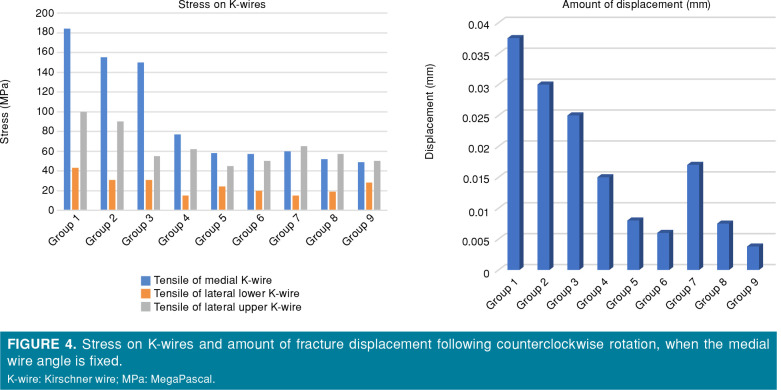
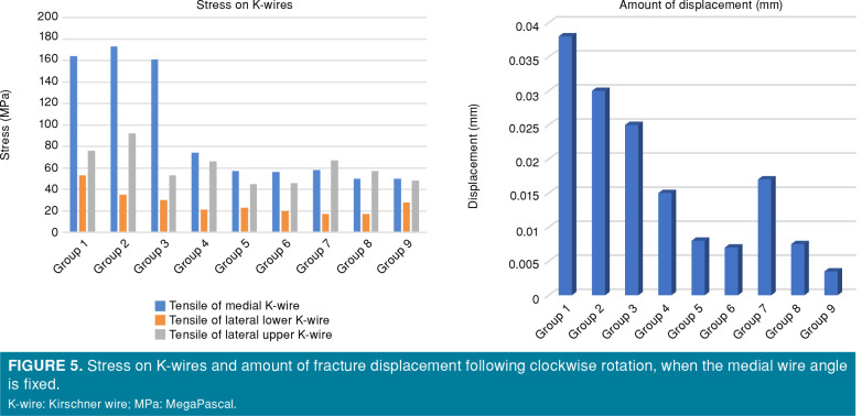
When the force was applied in the counterclockwise direction, the stresses were 58 megaPascal (MPa) on medial K-wire, 24 MPa on lower lateral K-wire, and 45 MPa on upper lateral K-wire in (45°, 45°) wire configuration. When the force was applied in the clockwise direction, the stresses were 57 MPa on medial K-wire, 23 MPa on lower lateral K-wire, and 45 MPa on upper lateral K-wire in (45°, 45°) wire configuration. In all models, the increased α and β angles were translated into the decreased stress on K-wires at the fracture level and decreased displacement under rotational deforming forces. Despite having generally lower fracture displacement, the increased α and β angles led to variable changes in the stress on K-wires against flexion and extension forces.
Conclusion
In supracondylar humerus fractures, increasing the insertion angle of both medial and lateral K-wires augments stabilization and reduces displacement, particularly against rotational deforming forces.
Keywords: Cross-wire fixation, fracture stabilization, supracondylar humerus fractures, wire insertion angle
Introduction
Supracondylar humerus fractures (SHFs) are the most common type of elbow fractures and most commonly affect children aged between four and eight years.[1,2] They are usually caused by falling onto the outstretched hand. Due to their anatomical proximity to nerves and vascular structures, SHF treatment should be carefully planned and implemented. Gartland type II and type III SHFs are usually treated with Kirschner wire (K-wire) fixation following open or closed surgical reduction.[3,4] Two of the most important factors which affect the outcome of SHF treatment are reduction quality and the quality of fixation to maintain reduction. Poor or insufficient fixation of the fracture can lead to the loss of reduction. There is a consensus about the configuration of K-wires. The most accepted one is two lateral and one medial K-wires crossing the fracture line.[5,6] However, the importance of the angle between the fracture and the K-wires in SHFs is still a question that needs to be answered.
Finite element analysis (FEA) is a mathematical method used in the analysis of some problems in many disciplines, such as engineering and mathematics, which provides interpretation on the behavior of materials based on the properties of material and applied forces.[7] This method is easy to apply and inexpensive. Such a practical and cost-effective method can assist clinicians in resolving some orthopedic problems. Undoubtedly, it may not possible to obtain precise results with this method. The results obtained should be also supported by biomechanically and clinical studies. However, we believe that the FEA method is the first step in resolving the problems in the practice of orthopedics.
The angle between the fracture and the K-wires can affect the results of surgical treatments for SHFs.[8] In the present study, we, therefore, aimed to evaluate this effect in a three-dimensional (3D) FEA model.
Patients and Methods
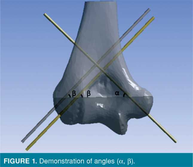
This study was conducted at Yozgat Bozok University Faculty of Medicine between January 2020 and June 2020. The need for an ethical approval was waived due to the study design. A 3D FEA in 3D adult distal humerus models with SHFs was used. Three K-wires were inserted to each model: one from medial and two parallel wires from lateral. The angle between the medial wire and the fracture line was represented by alpha (α), and the angle between the lateral wires and the fracture line was represented by beta (β) (Figure 1). A different combination of different angles (30°, 45°, and 60°) was used in each model, resulting in nine different (α, β) wire configurations (Table I).
Table 1. (α, β) combinations of groups.
| Groups | (α, β) angle values |
| 1 | 30°,30° |
| 2 | 30°,45° |
| 3 | 30°,60° |
| 4 | 45°,30° |
| 5 | 45°,45° |
| 6 | 45°,60° |
| 7 | 60°,30° |
| 8 | 60°,45° |
| 9 | 60°,60° |
Figure 1. Demonstration of angles (a, b).
Modeling and finite element simulations
The humerus models were developed using data obtained from 3D computed tomography scans. A fractured line was constructed using an open source tool, such as InVesalius (version 3.1) (Centro de Tecnologia da Informação Renato Archer (CTI), Brazil). In all models, non-comminuted, a reduced Gartland type III fracture model was created. Preparation of the model was continued by selecting and placing K-wires on it bicortically via SolidWorks® software (SolidWorks Corp., MA, USA). The diameter of the K-wires placed was set to 2 mm.
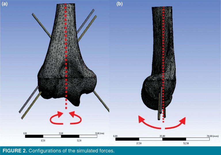
The prepared solid models were imported to Finite Element Simulation Software ANSYS workbench version 2020R1 (ANSYS Inc., Canonsburg, PA, USA) to create simulations. Using higher order Solid187 3D elements, the finite element mesh volume was obtained (Figure 2).
Figure 2. Configurations of the simulated forces.
Material properties
The properties of the materials used in the study were determined by reference to the previous studies.[9,10] Material properties were used for simulations as cortical bone Young modulus (E)=16 GigaPascal (GPa), υ=0.3 and E=200GPa, υ=0.33 as the K-wires and assumed linear elastic and isotropic.
The contact interfaces with the bone and K-wires were assumed as the bonded contact. The fracture interface was considered completely broken, frictional sliding contact, and 0.2 was taken as the friction coefficient.[9]
Properties of applied forces
Four different load configurations for each model were analyzed: with Moment (M)=1.5 Newton-meter (N.m) magnitude for 10 sec rotational (counterclockwise [CCW] and clockwise [CW]) moments; flexion and extension bending (Figure 2). For each K-wire model configuration, the upper side of the model was fixed as constraint, indicating that all nodes of the upper side of the K-wire model had zero displacements.
Assessment
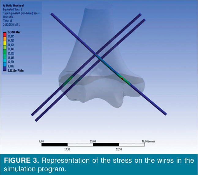
After force loading, the amounts of fracture displacement and the maximum stress on the K-wires at the level of the fracture line at the end of 10 sec were recorded and compared (Figure 3). The effects of different insertion angles on these values were calculated.
Figure 3. Representation of the stress on the wires in the simulation program.
The stress on the K-wires was evaluated in two stages. In the first stage, the (α) angle was constant and the (β) angle changed. That is, we compared and evaluated groups 1, 2, and 3; groups 4, 5, and 6; and groups 7, 8, and 9 among themselves. This revealed the effects of the insertion angle of the lateral K-wires on fracture stability. In the second stage, the (β) angle was constant and the (α) angle changed. We compared and evaluated groups 1, 4, and 7; groups 2, 5, and 8; and groups 3, 6, and 9 among themselves. Therefore, we were able to determine the effects of the insertion angle of the medial K-wire on fracture stability.
Results
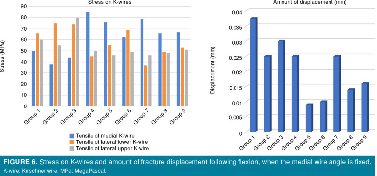
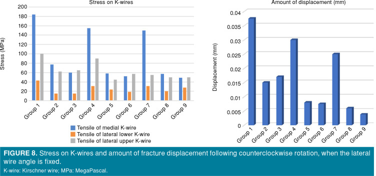
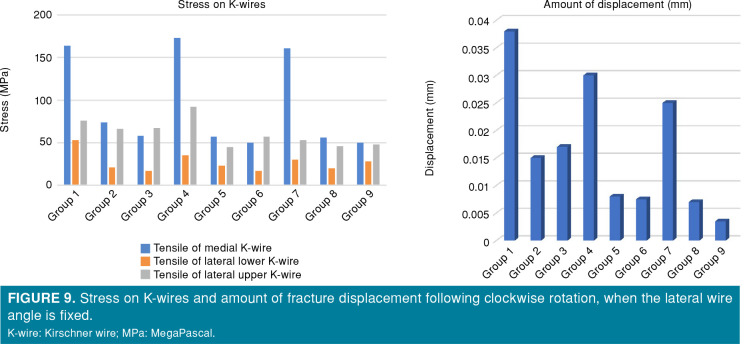
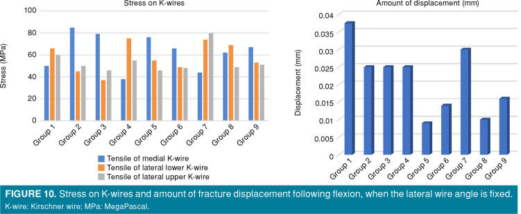
The maximum stress values on K-wires and amounts of displacement following loading are presented in Tables II and III, respectively.
Table 2. Maximum stress on K-wires and amount of fracture displacement after the simulation of rotation in clockwise and counterclockwise directions.
| Maximum stress on K-wires and amount of fracture displacement after the simulation of rotation in counterclockwise directions | Maximum stress on K-wires and amount of fracture displacement after the simulation of rotation in clockwise directions | |||||||
| Groups | Medial K-wire (MPa) | Lateral lower (MPa) | Lateral upper (MPa) | Displ (mm) | Medial K-wire (MPa) | Lateral lower (MPa) | Lateral upper (MPa) | Displ (mm) |
| 1 | 184 | 43 | 100 | 0.0375 | 164 | 53 | 76 | 0.038 |
| 2 | 155 | 31 | 90 | 0.03 | 173 | 35 | 92 | 0.03 |
| 3 | 150 | 31 | 55 | 0.025 | 161 | 30 | 53 | 0.025 |
| 4 | 77 | 15 | 62 | 0.015 | 74 | 21 | 66 | 0.015 |
| 5 | 58 | 24 | 45 | 0.008 | 57 | 23 | 45 | 0.008 |
| 6 | 57 | 20 | 50 | 0.006 | 56 | 20 | 46 | 0.007 |
| 7 | 60 | 15 | 65 | 0.017 | 58 | 17 | 67 | 0.017 |
| 8 | 52 | 19 | 57 | 0.0075 | 50 | 17 | 57 | 0.0075 |
| 9 | 49 | 28 | 50 | 0.0038 | 50 | 28 | 48 | 0.0035 |
| K-wire: Kirschner wire; MPa: megaPascal; Displ: Displacement. | ||||||||
Table 3. Maximum stress on K-wires and amount of fracture displacement after the simulation of flexion and extension.
| Maximum stress on K-wires and amount of fracture displacement after the simulation of flexion directions | Maximum stress on K-wires and amount of fracture displacement after the simulation of extension directions | |||||||
| Groups | Medial K-wire (MPa) | Lateral lower (MPa) | Lateral upper (MPa) | Displ (mm) | Medial K-wire (MPa) | Lateral lower (MPa) | Lateral upper (MPa) | Displ (mm) |
| 1 | 50 | 66 | 60 | 0.0375 | 35 | 38 | 61 | 0.0195 |
| 2 | 38 | 75 | 55 | 0.025 | 40 | 63 | 62 | 0.033 |
| 3 | 44 | 74 | 80 | 0.03 | 45 | 98 | 55 | 0.03 |
| 4 | 85 | 45 | 50 | 0.025 | 54 | 34 | 60 | 0.013 |
| 5 | 76 | 55 | 46 | 0.009 | 68 | 71 | 35 | 0.019 |
| 6 | 62 | 69 | 49 | 0.01 | 70 | 77 | 62 | 0.03 |
| 7 | 79 | 37 | 46 | 0.025 | 72 | 41 | 63 | 0.011 |
| 8 | 66 | 49 | 48 | 0.014 | 63 | 66 | 44 | 0.013 |
| 9 | 67 | 53 | 51 | 0.016 | 87 | 105 | 44 | 0.022 |
| K-wire: Kirschner wire; MPa: megaPascal; Displ: Displacement. | ||||||||
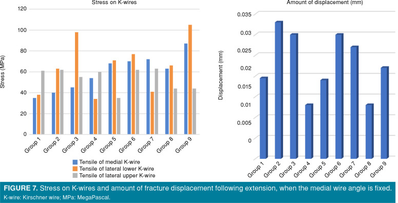
In the first stage, the stress on the medial wire and fracture displacement resulting from rotation (CW and CCW) decreased with increasing (β) angles in all groups (Figures 4 and 5). In the first stage, the stress on the medial wire and fracture displacement resulting from flexion were similar between the groups, where the (β) angles were 45° and 60° (Figure 6). However, the stress on the medial wire and fracture displacement increased in all groups with a (β) angle of 30°. The stress on the medial wire and fracture displacement resulting from extension increased with increasing (β) angles in all groups (Figure 7).
Figure 4. Stress on K-wires and amount of fracture displacement following counterclockwise rotation, when the medial wire angle is fixed. K-wire: Kirschner wire; MPa: MegaPascal.
Figure 5. Stress on K-wires and amount of fracture displacement following clockwise rotation, when the medial wire angle is fixed. K-wire: Kirschner wire; MPa: MegaPascal.
Figure 6. Stress on K-wires and amount of fracture displacement following flexion, when the medial wire angle is fixed. K-wire: Kirschner wire; MPa: MegaPascal.
Figure 7. Stress on K-wires and amount of fracture displacement following extension, when the medial wire angle is fixed. K-wire: Kirschner wire; MPa: MegaPascal.
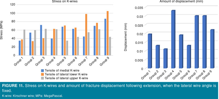
In the second stage, the stress on the lateral wire and fracture displacement resulting from the simulation of rotation (CW and CCW) decreased with increasing α angles in all groups (Figures 8 and 9). In the second stage, the stress on the lateral wire resulting from the simulation of flexion decreased with increasing (α) angles in all groups (Figure 10). The groups with α angles of 45° had the smallest fracture displacements. The stress on the lateral wire caused by the simulation of extension was not significantly affected by the insertion angles, while fracture displacement resulting from extension increased with increasing α angles (Figure 11).
Figure 8. Stress on K-wires and amount of fracture displacement following counterclockwise rotation, when the lateral wire angle is fixed. K-wire: Kirschner wire; MPa: MegaPascal.
Figure 9. Stress on K-wires and amount of fracture displacement following clockwise rotation, when the lateral wire angle is fixed. K-wire: Kirschner wire; MPa: MegaPascal.
Figure 10. Stress on K-wires and amount of fracture displacement following flexion, when the lateral wire angle is fixed. K-wire: Kirschner wire; MPa: MegaPascal.
Figure 11. Stress on K-wires and amount of fracture displacement following extension, when the lateral wire angle is fixed. K-wire: Kirschner wire; MPa: MegaPascal.
Discussion
Supracondylar humerus fractures frequently occur in children who fall onto an outstretched hand. Gartland classification is often used in planning the treatment of these fractures. Conservative treatment methods are recommended for Gartland type I fractures.[11] However, closed or open reduction followed by K-wire fixation is recommended in Gartland types II and III characterized by severe fracture displacement [3,12,13] In the literature, there are several mechanical and clinical studies investigating the ideal K-wire configuration for SHFs.[14]
In a review, Chen et al.[15] reported that there were no stability differences between the cross pinning and divergent lateral pinning in non-comminuted SHFs. Additionally, the authors suggested medial column pinning for fractures with medial comminution and showed that the pin size was directly proportional to stability. In another study, Gottschalk et al.[12] evaluated the effects of various pin configurations on stability in the treatment of SHFs. During their evaluation, the effects of the pin size and number were also discussed. The authors reported that the highest torsional resistance was in the capitellar starting group with an increased pin diameter. On the other hand, Solak and Aydin[16] demonstrated that there was no significant difference in the complication rates between the cross pinning and lateral pinning performed with two pins. However, in the literature, the incidence of neurological complications is higher, particularly in medial pinning. Skaggs et al.[17] also suggested that lateral pinning would be safer and more effective; therefore, medial pinning should be avoided. Similarly, Prashant et al.[18] reported consistent results with the abovementioned study. They recommended fixation with lateral pinning due to the low risk of iatrogenic ulnar nerve damage and similar clinical results to cross pinning. In their randomized study, however, Kocher et al.[19] found no significant difference between the cross pinning and lateral pinning. Contrary to those studies, Brauer et al.[20] argued that medial and lateral cross pinning provided a more stable configuration. In their biomechanical studies evaluating pinning techniques, Lee et al.[21] showed that cross pinning yielded the most stable configuration against axial rotational forces. When only lateral pinning was performed, they showed that divergent pinning was more stable than parallel pinning. Similarly, Weinberg et al.[22] reported that cross pinning was a more stable configuration. Taken together, there is no clear consensus on the ideal K-wire configuration. However, it can be speculated that, if a better stability is desired, the most accepted one is two lateral and one medial K-wires crossing the fracture line.[3,5,23]
Although the debate on the correct wire configuration is ongoing, there are no studies which investigate the effects of the changes in the angle between K-wire and the fracture line on the quality of fixation. It is difficult to plan clinical or mechanical studies examining this notion. In this context, we believe that modeling and simulation techniques developed for engineering purposes would be helpful. Liu et al.[6] compared fixation methods used in SHFs through a simulation program (3D FEA) and found cross K-wiring to be effective, particularly in transverse SHFs, as it increased resistance against rotation, flexion, and varus loading. They also compared their findings with other relevant studies and concluded that their findings were compatible with the literature. Another study which utilized a simulation program was conducted by Lamdan et al.[9] The authors compared cross and divergent wiring in the fixation of SHFs and concluded that bone-implant integration played a key role in fracture stability. In our study, we found that by increasing the insertion angle (i.e., the angle between the wires and the fracture line) decreased displacement and stress on the wires. The length of the K-wire that is inside the bone is directly proportional to bone-implant integration. Increasing insertion angles increases the length of the inserted bone, thereby increasing the bone-implant integration, which may explain our findings.
Another point to consider is that SHFs are usually not simple, but complex fractures that are often accompanied by comminution. Review of the literature reveals that fracture stability is more difficult to achieve in cases where there is significant medial comminution.[24] In a study, Larson et al.[24] evaluated the effects of different K-wire configurations on fracture stability in the SHF models with and without medial comminution. They demonstrated that fracture stabilization was more difficult to achieve in models with extensive medial comminution. It is important to plan the treatment accordingly in cases with medial comminution to prevent any complications which may develop after treatment. Therefore, our study contributes to medical practice by providing information about the stress on K-wires at the level of the fracture line in different angle configurations. The amount of fracture displacement is inversely proportional to the stress on the K-wire resulting from loading. Models with lower stress on K-wires require more force to achieve a similar level of displacement. Consequently, it would be wise to attempt and achieve a lower stress on the medial wire while treating fractures with extensive medial comminution. The same principle applies to the fracture models with lateral comminution, where it is preferable to decrease the stress on the lateral wire(s), while treating fractures with extensive lateral comminution. Our findings can, thus, guide medical practice (Table II).
Furthermore, these patients are usually followed for a certain period with a splint or plaster after surgery. Protective external fixation methods such as splints are usually more protective against rotational forces than valgus, varus, flexion, and extension forces. Therefore, ensuring rotational stability is of utmost importance in the treatment of these fractures. As shown in Table II, the reaction of the wires with the change of angle against rotational forces can be seen. Accordingly, increasing the angle between the fracture and K-wires under the same rotation forces reduces the tension on the wires.
On the other hand, our study is limited in that, in the real-life setting, deforming forces are combined and simultaneously act on fractures from different directions. In our study, we evaluated each force configuration individually. The stress on K-wires may vary under combined forces. Therefore, our data require clinical correlation. Nevertheless, we believe that our study would guide clinicians in choosing the appropriate wire configuration depending on the fracture type. Another problem that is commonly encountered in the clinical practice is the difficulty in directing the wires, while inserting them from medial. Due to the anatomical structure of the medial part of the distal humerus and the ulnar nerve, the medial wire cannot be always inserted with small angles. However, our study findings indicate that a higher insertion angle is preferable for the medial wire. In the literature, there is no study supporting our results, particularly on the vertical transmission of wires. However, Gottschalk et al.[11] showed that sending the wire over the capitellum increased stability. This can be attributed to two reasons. The first is due to the fact that the K-wire starts from a solid structure such as capitellum, and the second is due to the increase in the distance that the wire can travel within the bone. Sending the K-wire over the capitellum increases the insertion of the wire, which allows the wire to travel more in the bone.
Another aspect of the study that has come under criticism is that the study was performed in 3D adult distal humerus models due to some reservations during modelling. When the structure of the pediatric distal humerus is examined, there are different physis (i.e., medial epicondyle, lateral epicondyle) in different ossification stages and normal bone structure. This causes the structure of the models to be used in the study to be heterogeneous, such as Young’s modulus. Another reason for not being able to use the pediatric humerus model is that the physis lines are not seen during 3D reconstruction. Therefore, secondary ossification centers, which normally do not have movement, also act as independent parts.
In our study, we used modeling and simulation programs used in engineering to seek a solution for a problem that is difficult to investigate and apply in medical practice. We demonstrated how the angle between the percutaneous K-wires and the fracture line affected the stress on and the displacement of the fracture.[25]
In conclusion, we have obtained the following results: (i) increasing the insertion angle of the lateral wires enhances the stability of the fracture against rotational deforming forces by decreasing the stress on the medial wire and the displacement of the fracture; (ii) increasing the insertion angle of the lateral wires enhances the stability of the fracture against flexion forces, but reduces stability against extension forces; (iii) increasing the insertion angle of the medial wires enhances the stability of the fracture against rotational deforming forces by decreasing the stress on the lateral wires and the displacement of the fracture; and (iv) increasing the insertion angle of the medial wires enhances the stability of the fracture against flexion and extension forces.
Footnotes
Conflict of Interest: The authors declared no conflicts of interest with respect to the authorship and/or publication of this article.
Financial Disclosure: The authors received no financial support for the research and/or authorship of this article.
References
- 1.Ralles S, Murphy M, Bednar MS, Fishman FG. Surgical Trends in the Treatment of Supracondylar Humerus Fractures in Early Career Practice: An American Board of Orthopaedic Surgery (ABOS) Part-II Database Study. J Pediatr Orthop. 2020;40:223–227. doi: 10.1097/BPO.0000000000001493. [DOI] [PubMed] [Google Scholar]
- 2.Holt JB, Glass NA, Shah AS. Understanding the epidemiology of pediatric supracondylar humeral fractures in the united states: identifying opportunities for intervention. e245-e251J Pediatr Orthop. 2018;38 doi: 10.1097/BPO.0000000000001154. [DOI] [PubMed] [Google Scholar]
- 3.Ladenhauf HN, Schaffert M, Bauer J. The displaced supracondylar humerus fracture: indications for surgery and surgical options: a 2014 update. Curr Opin Pediatr. 2014;26:64–69. doi: 10.1097/MOP.0000000000000044. [DOI] [PubMed] [Google Scholar]
- 4.Barr LV. Paediatric supracondylar humeral fractures: epidemiology, mechanisms and incidence during school holidays. J Child Orthop. 2014;8:167–170. doi: 10.1007/s11832-014-0577-0. [DOI] [PMC free article] [PubMed] [Google Scholar]
- 5.Edmonds EW, Roocroft JH, Mubarak SJ. Treatment of displaced pediatric supracondylar humerus fracture patterns requiring medial fixation: a reliable and safer cross-pinning technique. J Pediatr Orthop. 2012;32:346–351. doi: 10.1097/BPO.0b013e318255e3b1. [DOI] [PubMed] [Google Scholar]
- 6.Liu C, Kamara A, Liu T, Yan Y, Wang E. Mechanical stability study of three techniques used in the fixation of transverse and oblique metaphyseal-diaphyseal junction fractures of the distal humerus in children: a finite element analysis. J Orthop Surg Res. 2020;15:34–34. doi: 10.1186/s13018-020-1564-4. [DOI] [PMC free article] [PubMed] [Google Scholar]
- 7.Mills NJ. Finite element modelling of foam deformation [Internet]. In: Mills NJBT-PFH, editor. Chapter 6. Oxford: Butterworth-Heinemann; 2007. p. 115-45. Available at: http://www.sciencedirect.com/science/article/pii/ B9780750680691500076 [Accessed: October 12, 2007] [Google Scholar]
- 8.Atik OŞ. Is there something new and interesting in my article. Eklem Hastalik Cerrahisi. 2019;30:69–69. doi: 10.5606/ehc.2019.003. [DOI] [PubMed] [Google Scholar]
- 9.Lamdan R, Liebergall M, Gefen A, Symanovsky N, Peleg E. Pediatric supracondylar humerus fractures: effect of bone- implant interface conditions on fracture stability. J Child Orthop. 2013;7:565–569. doi: 10.1007/s11832-013-0533-4. [DOI] [PMC free article] [PubMed] [Google Scholar]
- 10.Ling M, Zhan S, Jiang D, Hu H, Zhang C. Where should Kirschner wires be placed when fixing patella fracture with modified tension-band wiring. A finite element analysis. J Orthop Surg Res. 2019;14:14–14. doi: 10.1186/s13018-019-1060-x. [DOI] [PMC free article] [PubMed] [Google Scholar]
- 11.Rupp M, Schäfer C, Heiss C, Alt V. Pinning of supracondylar fractures in children - Strategies to avoid complications. S2-S9Injury. 2019;50 Suppl 1 doi: 10.1016/j.injury.2019.03.042. [DOI] [PubMed] [Google Scholar]
- 12.Gottschalk HP, Sagoo D, Glaser D, Doan J, Edmonds EW, Schlechter J. Biomechanical analysis of pin placement for pediatric supracondylar humerus fractures: does starting point, pin size, and number matter. J Pediatr Orthop. 2012;32:445–451. doi: 10.1097/BPO.0b013e318257d1cd. [DOI] [PubMed] [Google Scholar]
- 13.Salonen A, Pajulo O, Lahdes-Vasama T, Välipakka J, Mattila VM. Increased incidence of distal humeral fractures and surgical treatment in 0- to 18-year-old patients treated in Finland from 1987 to 2010. J Child Orthop. 2013;7:559–564. doi: 10.1007/s11832-013-0529-0. [DOI] [PMC free article] [PubMed] [Google Scholar]
- 14.Dekker AE, Krijnen P, Schipper IB. Results of crossed versus lateral entry K-wire fixation of displaced pediatric supracondylar humeral fractures: A systematic review and meta-analysis. Injury. 2016;47:2391–2398. doi: 10.1016/j.injury.2016.08.022. [DOI] [PubMed] [Google Scholar]
- 15.Chen TL, He CQ, Zheng TQ, Gan YQ, Huang MX, Zheng YD, et al. Stiffness of various pin configurations for pediatric supracondylar humeral fracture: a systematic review on biomechanical studies. J Pediatr Orthop B. 2015;24:389–399. doi: 10.1097/BPB.0000000000000196. [DOI] [PubMed] [Google Scholar]
- 16.Solak S, Aydin E. Comparison of two percutaneous pinning methods for the treatment of the pediatric type III supracondylar humerus fractures. J Pediatr Orthop B. 2003;12:346–349. doi: 10.1097/01.bpb.0000060288.16932.08. [DOI] [PubMed] [Google Scholar]
- 17.Skaggs DL, Hale JM, Bassett J, Kaminsky C, Kay RM, Tolo VT. Operative treatment of supracondylar fractures of the humerus in children. The consequences of pin placement. J Bone Joint Surg [Am] 2001;83:735–740. [PubMed] [Google Scholar]
- 18.Prashant K, Lakhotia D, Bhattacharyya TD, Mahanta AK, Ravoof A. A comparative study of two percutaneous pinning techniques (lateral vs medial-lateral) for Gartland type III pediatric supracondylar fracture of the humerus. J Orthop Traumatol. 2016;17:223–229. doi: 10.1007/s10195-016-0410-2. [DOI] [PMC free article] [PubMed] [Google Scholar]
- 19.Kocher MS, Kasser JR, Waters PM, Bae D, Snyder BD, Hresko MT, et al. Lateral entry compared with medial and lateral entry pin fixation for completely displaced supracondylar humeral fractures in children. A randomized clinical trial. J Bone Joint Surg [Am] 2007;89:706–712. doi: 10.2106/JBJS.F.00379. [DOI] [PubMed] [Google Scholar]
- 20.Brauer CA, Lee BM, Bae DS, Waters PM, Kocher MS. A systematic review of medial and lateral entry pinning versus lateral entry pinning for supracondylar fractures of the humerus. J Pediatr Orthop. 2007;27:181–186. doi: 10.1097/bpo.0b013e3180316cf1. [DOI] [PubMed] [Google Scholar]
- 21.Lee SS, Mahar AT, Miesen D, Newton PO. Displaced pediatric supracondylar humerus fractures: biomechanical analysis of percutaneous pinning techniques. J Pediatr Orthop. 2002;22:440–443. [PubMed] [Google Scholar]
- 22.Weinberg AM, Castellani C, Arzdorf M, Schneider E, Gasser B, Linke B. Osteosynthesis of supracondylar humerus fractures in children: a biomechanical comparison of four techniques. Clin Biomech (Bristol, Avon) 2007;22:502–509. doi: 10.1016/j.clinbiomech.2006.12.004. [DOI] [PubMed] [Google Scholar]
- 23.Dineen HA, Stone J, Ostrum RF. Closed Reduction Percutaneous Pinning of a Pediatric Supracondylar Distal Humerus Fracture. S7-S8J Orthop Trauma. 2019;33 Suppl 1 doi: 10.1097/BOT.0000000000001523. [DOI] [PubMed] [Google Scholar]
- 24.Larson L, Firoozbakhsh K, Passarelli R, Bosch P. Biomechanical analysis of pinning techniques for pediatric supracondylar humerus fractures. J Pediatr Orthop. 2006;26:573–578. doi: 10.1097/01.bpo.0000230336.26652.1c. [DOI] [PubMed] [Google Scholar]
- 25.Atik OŞ. What are the expectations of an editor from a scientific article. Jt Dis Relat Surg. 2020;31:597–598. doi: 10.5606/ehc.2020.57896. [DOI] [PMC free article] [PubMed] [Google Scholar]


