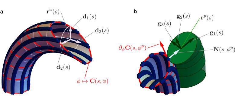
Figure 4. Details of the mechanical model.
(a) Geometry of the Ax. MTs lie on a tubular surface parametrized by generalized polar coordinates and , where is the arc length of the axonemal centerline . The unit vectors and lie on the orthogonal cross sections of the Ax (light blue circles). The material sections of the Ax are given by the curves (red), which connect points of neighbouring axonemal MTs corresponding to the same arc length . Bend deformations of the axoneme are generated by the shear (collective sliding) of MTs. The shear is quantified by the angle between the orthogonal sections and the material sections of the Ax. (b) Geometry of the euglenid flagellum, detail of the Ax-PFR attachment. The unit vectors and generate the plane of the PFR’s cross sections. The vector is parallel to the outer unit normal to the axonemal surface , while is parallel to the tangent vector to the material section .

