

Abstract
We present a design overview of the MIT 1.3-GHz LTS/HTS NMR magnet (1.3G) with a newly designed 835-MHz REBCO insert (H835) as a replacement for the 800-MHz REBCO insert (H800) that was damaged when it quenched during operation in 2018. The new H835 is designed to contribute 19.6 T in a background field of 10.93 T by an LTS NMR magnet that normally rated at 11.74 T (500 MHz): combined, 1.3G generates a total field of 30.53 T corresponding to a proton resonance frequency of 1.3 GHz. H835 is designed to operate stably while meeting 1.3G design constraints. We have also designed H835 to protect it from permanent damage in an improbable event like a quench. Key design features are: 1) a single-coil formation, composed of 38 stacked metal-co-wound no-insulation and 2 stacked no-insulation double-pancake coils, all with mechanically improved cross-over sections; 2) enhanced thermal stability; and 3) reduced current margin with a detect-and-heat method. This paper includes: 1) electromagnetic and mechanical design of H835; 2) cryogenics overview; 3) quench protection strategy; and 3) discussion on the next steps to successfully complete 1.3G.
Keywords: High-Field Magnets, HTS Magnets, No-Insulation Winding Technique, Nuclear Magnetic Resonance, REBCO tape
I. Introduction
The final phase of a high-resolution 1.3-GHz low-temperature superconducting (LTS)/high-temperature superconducting (HTS) nuclear magnetic resonance (NMR) magnet (1.3G) incorporating our new HTS insert magnet design began in August 2020 at the Massachusetts Institute of Technology Francis Bitter Magnet Laboratory (MIT FBML). Our first 800-MHz HTS insert (H800) quenched at 18 T during operation in 2018 and was damaged [1], [2]. We have a new 835-MHz HTS insert (H835) design, based on our post analysis of the previous H800.
In this paper, we present a technical overview of 1.3G in electromagnetic, mechanical, cryogenic, and protection aspects. We first introduce, in section II, enhanced and new features of H835 compared with H800. Then, in section III, we present: the design results with fundamental—critical current (Ic), homogeneity, and forces/stresses—analyses of H835; cryogenics—thermal-conductive spacers, current leads, cryogen, cryostats—overview; and quench protection technique for 1.3G. We conclude with discussion on the next steps and expected challenges to successfully achieve 1.3G.
II. Enhanced Features in a New HTS Insert
H800 was composed of 3-radially-nested coils, each of which was a stack of no-insulation (NI) REBCO double-pancake (DP) coils. Despite our efforts to design and manufacture H800 that would perform successfully [3]–[10], H800 quenched during its first operation, and most of its 96 DP coils were permanently damaged over [1], [2], Here we present what we believe an improved replacement of H800, H835 into which we incorporated new features acquired from the H800 experience.
Single-coil magnet
Most damage in H800 occurred by mechanical over-stress rather than electrical breakdown or overheating. The H800 quench was initiated at the bottom of the middle coil (Coil 2) of the 3-nested-coil formation. The quench induced large azimuthal currents in the inner (Coil 1) and the outer (Coil 3) coils, in turn generated huge unbalanced forces and over-stresses in them. One obvious option to eliminate the unbalance forces among nested NI coils during operation and quench is a single-coil H835, a stack of NI DP coils as each of three stacks in H800.
Higher field contribution
We design H835 to increase its field contribution from 18.79 T (800 MHz) to 19.6 T (835 MHz), chiefly to make the 500-MHz LTS background magnet (L500) contribute a field of 10.93 T, lower than its nominal field of 11.74 T. As discussed further in section III, by providing an additional current margin, we alleviate protection burden for L500 in case the HTS insert quenched.
Metal Co-wound 4-mm REBCO Tape
The most H835 DP coils, except end DP coils, will be wound with a 4-mm-wide REBCO tape together co-wound with a stainless-steel tape [11], [12]. Compared with H800 in which all NI DP coils were wound with only 6-mm REBCO tapes, H835 has advantages: 1) less screening current effects from narrower tapes (4 mm vs. 6 mm); 2) higher tum-to-turn contact resistance, Rct leads to a shorter charging-delay time constant and reduces induced currents during quench; and 3) during quench, less Ic margin in 4-mm tapes (vs. 6-mm tapes) results in smaller induced currents that in turn lead to less mechanical stresses/forces.
Thermal conductive spacers
When H800 was charged at a rate of 0.01 A·s−1, a voltage of 1–2 mV appeared at ~190 A in both Coils 2 and 3 that disappeared when the power supply current was held steady at 190 A. Generally, voltage upticks that appear in NI coils during charging results in a temperature rise within the NI coils, caused by charging-induced dissipation. In H835, we will insert a thermally conductive, but electrically insulated, cooling sheet between DP coils to extract this dissipation within the winding to heat sink (solid nitrogen) at the winding’s outside diameter (OD).
Protection heaters
In H835, we will also insert bifilar disk-shaped heaters between DP coils: 1) to increase Top of the selected DP coils during its stand-alone test thereby to reduce screening currents [13], [14]; and 2) for protection, quickly to drive the entire H835 DP coils into the normal state.
Reinforced cross-over turns
Many voltage spikes in Coils 2 and 3, a sudden quench, and post-quench examinations and analyses indicate that a conductor defect caused by a series of conductor slips at the cross-over turn, specifically in the end DP coils in Coil 2, triggered the H800 quench [2]. As described later, we will reinforce cross-over turns of the all DP coils mechanically and electrically.
Solid nitrogen cooling
Our 1.3G will have a new cryogenic feature that includes solid nitrogen (SN2) and a cryocooler to ameliorate the scarcity of liquid helium, and possibly to operate the H835 only at a higher temperature (e.g. 10 K) to minimize the screening current effects.
Self-supported helical HTS current leads
Double-layered 12-mm REBCO tapes will be soldered at the bottom of the single-coil H835, wrapped upward over the outer surface of each over-banding layer, and mechanically self-supported.
III. H835 Design Results
A. Design Constraints
We have reviewed design requirements for the HTS insert magnet for our 1.3G. As with H800 [4], L500 of a 237-mm cold bore, verified to generate 11.74 T at 246 A in the temperature range 4.2–6.0 K [15], is again designated as a background magnet for our 1.3G. A new HTS insert magnet must generate a field of ≥18.79 T to achieve a 30.53 T (1.3 GHz) and its overall OD must be small enough to fit comfortably within a 237-mm diameter bore. The requirements dictate the HTS insert to operate at a high current density, a challenging specification.
For a stable HTS insert magnet operation, our design targets an operating current vs. minimum critical current (Iop/Ic) of ≤70%, a maximum hoop strain within a winding of ≤0.45% [16]–[18], and negative radial stresses, i.e., compressive between turns in all pancake coils. Then, as described in section II, we aim to make a field contribution from HTS as large as possible while meeting above requirements. Eventually, our 1.3G, like all the other NMR magnets, its field must have a spatial homogeneity of ≤0.01 ppm over volume of 1-cm DSV (diameter of spherical volume) and a temporal stability of ≤0.01 ppm/hr. Although the field of as-built magnet must be further shimmed after the magnet has been charged, our as-designed H835 will have a homogeneity of <5 ppm (peak-peak) over 3-cm DSV.
B. Electromagnetic Design Results
A first-cut design has been performed that meets the essential requirements and constraints presented in section III.A. Table I shows the key parameters of our first-cut design. Figure 1 presents pictorial details of H835: Left, a schematic cross-sectional view; Right, computed Ic distribution in the winding at Iop=230 A over top half. To calculate the H835 Ic distribution, we used the short sample Ic(B, θ, 4.2 K) data of SuperOx 4-mm REBCO tape [19], extrapolating the data for 6-mm end DP coils. Note that the SuperOx data for this distribution may be conservative considering some commercially available REBCO tapes have greater Ic than SuperOx [20]. As indicated in Table I, H835 is composed of 40 NI DP coils, which except 2 NI DP coils in two ends, are co-wound with a 4-mm-wide, 65-μm-thick REBCO tape and a high-strength stainless steel (SS304) tape, while the 4 end DP coils are wound only with a 6-mm wide, 75-μm-thick REBCO tape and no SS304 tape. By making the entire winding pack operate at the same conductor-current density, we have managed to make the minimum Ic of 330 A (>Iop/0.7).
TABLE I:
Key parameters of first-cut design of the H835
| Notch | Regular | End | ||
|---|---|---|---|---|
| RBCO tape width; thickness | [mm] | 4; 0.065 | 6; 0.075 | |
| Co-winding SS304 tape width; thickness | [mm] | 4; 0.050 | N/A | |
| Spacer thickness | [mm] | Internal DP: 0.13 (G10); Between DPs: 0.54 (cool-disk & heater) | ||
| Coil ID; OD @ 4.2 K | [mm] | 90.29; 161.41 | 88.00; 161.41 | 88.00; 161.45 |
| Overall OD including Over-banding | [mm] | 212 | ||
| Number of DP coils | 10 | 2 × 14 | 2 × 1 | |
| Number of turns per DP coil | 620 | 640 | 982 | |
| Tape length per DP coil | [m] | 246 | 250 | 384 |
| Total conductor length | [m] | 9.500 | 770 | |
| Inductance | [H] | 20.8 (H835), 152.7 (L500), 15.65 (Mutual H835 & L500) → 205 (1.3G) | ||
| Operating current, Iop | [A] | 230 (both H835 and L500) | ||
| Designed B0 field @ Iop | [T] | 19.7 | ||
| Homogeneity @ 4.2 K: H835; 1.3G | [ppm] | 1.34 ppm (3-cm DSV), 0.037 ppm (1-cm DSV); 2.09 ppm (3-cm DSV), 0.057 ppm (1-cm DSV) | ||
| 5-Gauss fringe field radius of 1.3G | [m] | (Axial) 7.66 × (Radial) 6.06 | ||
| Estimated min. Ic @ 4.2 K | [A] | > 330 | ||
| Max. hoop strain (magnetic + bending)* | [%] | <0.4 (with an 25-mm-thick SS304 tape over-banding) | ||
| Avg. midplane axial pressure | [MPa] | 115 | ||
Winding tension, cooling-down and screening-current-induced-strain effects are not included.
Fig. 1.

Pictorial details of H835: (left) schematic cross-sectional view; (right) computed Ic distribution at Iop=230 A over top half
We adopt a notched-coil design to improve the field homogeneity of our H835, a relatively short and thick magnet. Note that notch coils increase degrees of freedom for design optimization. The computed homogeneity of as-designed 1.3G with H835 is 1.34 ppm at 3-cm DSV and 0.037 ppm at 1-cm DSV, and significant field errors will be added for the as-built 1.3G because of manufacturing tolerance and uncertainty, and screening-current-induced field (SCF) of H835. To achieve the ultimate homogeneity goal for 1.3G of ≤0.01 ppm at 1-cm DSV, we will first apply our HTS inner shim coils, then ferromagnetic shims, successfully used in HTS magnet shimming too [21], [22], and finally rely on room-temperature (RT) copper slum coils, widely used in conventional NMR magnets.
We have performed screening current analysis by using T-A formulation with a 2-dimensional continuous approximation for the coil winding of hundreds turns [23]. Figure 2a shows the analysis result of normalized current density distribution within the windings of top 20 NI DP coils. These non-uniformly distributed current density generates unwanted field errors containing a quite strong Z2 harmonic error term and negative BO field of −0.224 T, as shown in Fig. 2b. We can deal with these detrimental effects of SCF by increasing B0 field and compensating the other field errors with shimming. In the next section, we also see how SCF affects H835 mechanically.
Fig. 2.

Screening current analysis in the H835: (a) normalized current distribution within the windings of top 20 NI DP coils; and (b) homogeneity along the axial position: as-designed field vs. field with SCF.
C. Mechanical Aspect
For high-field superconducting magnet design, the key determinant parameter would be the internal stress within the winding caused by huge Lorentz forces. In the H835, we will investigate the radial-force (Bz×jϕ) inducing hoop stresses and strains in the REBCO pancake winding, and the axial-force (−Br×jϕ) exerted on the winding surface and the cross-over turns. To estimate the peak strain in the winding, the following factors need to be considered: 1) bending radius; 2) winding tension; 3) over-banding; 4) thermal-contraction during cool-down; and 5) energization incorporating screening currents. Especially, for REBCO magnets like our H835, unlike the magnets wound with conventional LTS wires having twisted multi-filaments, the screening-current-induced stress (SCS) in a REBCO tape must be taken into account when determining the peak strain. We first performed solid mechanical analysis of every pancake coil of a top half H835 with only considering thermal contraction and energization by using a finite element method (FEM). Figure 3a shows computed peak stresses in the REBCO winding and the orthotropic mechanical properties used in this analysis are listed in Table III. Note that the peak stresses with current density, J incorporating screening currents were significantly higher than those with uniform J. Each pancake model includes a winding bobbin, all turns of REBCO and co-wound SS304 tapes, and 25-mm over-banding (250 turns of 0.1-mm-thick SS304 tapes). All contact boundaries were assumed to be frictionless contact; the bottom line of the winding was constrained to move only in the radial; and the other outlines including the top of the pancake winding were set to be freely moved. The highest peak stress and strain. 1050 MPa and 0.7%, were in the end pancake coil (Pancake #2) and the second highest of 960 MPa and 0.64% in the Pancake #16, and their stress distributions are shown in Fig. 3b. When we applied a winding tension of 110 MPa for both REBCO/SS304 co-winding and SS304 over-banding, the peak stress dropped by ~200 MPa, e.g. the re-computed peak stress in Pancake #16 was 750 MPa. Although the winding tension in real cannot be ideal as computed, the winding tension will help to reduce the hoop stress level of H835. The REBCO tape will be wound with facing its HTS layer side inward, which results in compressive bending strain of −0.048% at the innermost turn. Also, the boundary conditions ignored in the analysis—friction between a winding surface and a spacer, and friction between turns—affect a lot to the peak stress level. The stress level can be changed as the winding is deformed, in turn degrading Ic and reducing the screening currents [24]. A torque on the REBCO tape winding generated by screening currents may tilt the winding align with the applied magnetic field direction, and it can reduce the induced screening current on those tilted tapes [25]. We believe that the peak stress computation with a screening current effect is highly over estimated. However, for H835 operation, we can reduce the screening currents by two ways: 1) operating H835 alone at a higher temperature (lower Jc) than 4.2 K, and 2) external field shaking with L500 (e.g. L500→0→⋯→IL500) which we plan to operate with a separate power supply. We may also consider using striated multi-sectional tapes or stacked narrower tapes instead of 6-mm wide tapes in the end DP coils, each of which requires further investigation of its effect and practical feasibility.
Fig. 3.
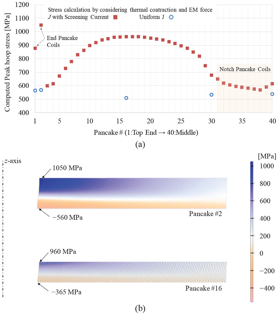
H835 hoop stress (a) computed results of peak hoop stress in each pancake coil with the frictionless contact all-turn pancake model; (b) Cross-sectional view of stress distribution in Pancake #16 and #2.
TABLE III.
Equivalent mechanical properties of SS304-co-wound and no-insulation REBCO winding pack
| Orthotropic properties @ 4.2 K (r; ϕ; z) | REBCO (4)* +SS304 | REBCO (6)* | SS304 | |
|---|---|---|---|---|
| Young’s modulus (E) | [GPa] | 155; 168; 168 | 134; 147; 147 | 210; 210; 210 |
| Poisson’s ratio (vrϕ; vϕz; vzr) | 0.29; 0.31; 0.30 | 0.30; 0.33; 0.31 | 0.28; 0.28; 0.28 | |
| Thermal contraction RT→4.2 K (ΔL/L | [%] | 0.27; 0.26; 0.26 | 0.27; 0.24; 0.24 | 0.30; 0.30; 0.30 |
REBCO (4) and (6) are 4-mm and 6-mm wide 75-μm-thick REBCO tapes, respectively.
Axial forces are applied on the winding surface of each NI pancake coil, i.e. pressure on a narrow side-face of the REBCO tape. Gupta et al. performed axial loading tests with NI test coils, wound with relatively thick—40 μm and 65 μm—copper matrix and a same 50-μm-thick Hastelloy substrate, and no significant degradation of the coil Ic were observed till 200 MPa or even higher pressure [26], [27]. The accumulated maximum pressure on the midplane of om H835 is computed to 115 MPa under 1.3G operation, which should be safe enough. On the innermost crossover sections of the H835 DP coils, the exerted axial forces up to ~430 N (at the both end DP coils in the full-current operation) toward the midplane can damage the unsupported crossover turn and degrade its Ic, observed in om previous H800 as shown in Fig. 4a. To reinforce the crossover turns, we will affix the additional REBCO tape by soldering, i.e. double-layered REBCO tape, on the crossover turns to enhance mechanical strength and current-carrying capacity. Then, the H835 DP coil with the double-layered crossover turn will be wound on an Inconel-718 winding ring having a crossover supporting frame, a schematic drawing of which is shown in Fig. 4b.
Fig. 4.

Mechanical reinforcement for cross-over turns in DP coils: (a) damaged cross-section turn in a DP coil of H800; (b) a concept drawing of a cross-over support on a winding ring.
H835 stack of DPs, as in om previous HTS inserts, are assembled on a central supporting stainless steel tube that acts as a centering member and minimize radial motion of individual DP coils. Flanges at the ends of this supporting structure have provisions for jacking screws, that acting on Belleville washers provide an axial preload necessary to ensure that it maintains elastic behavior, preventing excessive deformation and/or sudden movement of the stacked DP coils during cool-down and energization.
D. Cryogenics Overview
H835 is rigidly connect to the L500 top and bottom flanges via four equally spaced non-magnetic SS304L threaded rods, which allow during system integration a very precise alignment of L500 and H835 magnetic centers. The assembled L500/H835 is fixed on the SN2/LHe vessel bottom plate.
As indicated in Fig. 5, both L500 and H835 coils are completely immersed in SN2 at slightly above 4.2 K. Our 1.3G will rely on a 4.2-K cryocooler, which will be used primarily to solidity LN2, and cool down SN2 to <5 K. A small volume of LHe may be used on top of SN2 to ensure a constant 4.2-K operating temperature when operating L500 and 1.3G in case of an excessive heat input, and LHe may be recondensed by the cryocooler. Note that the fringe magnetic field on an unshielded cryocooler is 500–550 Gauss, which may prevent the cryocooler from supplying its full cooling capacity (manufacturer recommendation is ≤350 Gauss) at the operating temperature. The 1st stage of two-stage cryocooler may be used for current leads cooling to replace vapor leads which have potential risk of being blocked during operation. A 2nd stage can reduce a total boiling rate of liquid helium.
Fig. 5.

A schematic view of the 1.3G cryostat system.
The enabling and innovative features of SN2 in 1.3G are:
to eliminate the possibility of trapped helium bubbles in high fields [30]–[32];
to keep the entire magnet system temperature uniform within <0.5 K even without LHe;
to have less pressure build inside the cryostat if the magnet quench occurs;
to enable H835, during a standalone operation, to be operated at >10 K to reduce its Jc (though Jc varies widely over the entire winding), and thus SCS;
to reduce SCS by impregnating the H835 winding with SN2, acting as a semi-bulk.
The 1.3G system will be fully implemented with provisions for high current leads, shim coils leads, instrumentation wiring and safety devices like a relief valve and a burst disk.
E. Protection Strategy of 1.3G
H835 standalone
A simple lumped parameter circuit model for NI DP coils [33], in which each DP coil is composed of an equivalent inductance and a resistance, were used to investigate the H835 quench behavior as the first step. Equivalent tum-to-turn resistance used for SS304-co-wound 4-mm NI DP coils and 6-mm NI DP coils were 50 mΩ and 2 mΩ, respectively [2]. We assumed that a sudden quench initiated from a top pancake coil (#1) and each DP coil is thermally isolated because the magnetic propagation is much faster than axial thermal diffusion between DP coils [34]. The maximum induced current and the maximum average temperature in the H835 DP coils were computed to 500 A and 140 K, respectively. The single-coil H835 standalone is self-protecting.
L500
We will charge L500 to its full operation current first to let L500 experience a possible, but improbable, premature quench prior to operating it together with H835. To use L500 for shaking H835, we can separately control the operating current of L500 down to zero and back to Iop during the H835 operation. Because L500 will operate at 230 A, with 30-A current margin, and thus unlikely quench. Assuming the H835 current suddenly decayed to zero, the average current induced in L500, ΔIL500, will be 23.6 A (=Mmutual/LL500×Iop, see Table I), still safe against over-strain in L500. However, L500 quench can cause over-strain issue in the H835 NI DP coils due to large induced currents without active protection. We will use quench-back heaters to heat up the H835 DP coils to minimize the induced current.
1.3G with H835 and L500
Here is our protection scenario in our 1.3G operation if H835 quenches: 1) quench initiated in a hot spot only due to HTS defect (different from LTS magnet quench by wire movement or epoxy crack); 2) no thermal runaway but slow quench in an initially quenched coil (only possible in No-Insulation feature) and sufficient time to detect; 3) ran a protection method (heater activate and/or run-down the power); and 4) protect the remaining coils in H835 and L500.
Unlike LTS, HTS (REBCO) magnets may not quench abruptly due to a much stability margin; one quench source not to be overlooked is conductor defect caused mechanically or metallurgically [35]. Detected defected DP coil will not be trained like LTS. For H835, a stack of DP coils, defective coils can be replaced with new DP coils.
IV. Expected Challenges and Next Steps toward 1.3 G
We have reviewed the first-cut design of the MIT 1.3G with a newly proposed H835 in the key design issues.
With respect to electromagnetic and mechanical issues, the most uncertain parameter is the peak strain in the REBCO tape. To minimize the risk of unanticipated failure by a mechanical stress overload, we will build trial full-scale DP coils of H835 and perform overstress testing by increasing its transportation current under a background magnet to ascertain that our stress calculation incorporating the screening-current effect and its reduction method by adjusting the operating temperature. At the same time, we will investigate a practical feasibility of using 1) 3-segmented 6-mm wide REBCO tapes, and 2) two-piled 3-mm tapes for the end DP coils to reduce the screening current effects. In cryogenics, we will test L500 alone up to 246 A at ≤6 K with our proposed SN2 cooling in the final cryostat (Fig. 5). We expect to validate and confirm our proposed SN2 cooling technique with a 1-W cryocooler and conduction-cooled HTS leads as well as L500 performance. Although we believe that both H835 and L500 are unlikely to quench, we will complete detailed quench analysis [36], [37], and further study the operation sequences and corresponding quench scenarios of the 1.3G, to minimize the risk of permanent damage in H835. A protection heater will be demonstrated in the trial coil testing.
V. Conclusion
In this paper, we have introduced a new single-coil, wide-bore 835-MHz REBCO insert magnet (H835) for the MIT 1.3-GHz NMR magnet. We believe that a single-coil formation adopted in H835 will eliminate huge unbalancing forces between nested NI coils observed in H800. Because calculated screening-current-induced azimuthal peak strain indicates that the conductor would be strained close to or even over 0.45%, we plan to overstress trial H835 DP coils and validate that they remain intact with or without our proposed screening current reduction method. Our first target is to build H835 and demonstrate it successfully generates a center field of 19.6 T. Next target is to combine H835 with L500, and achieve a non-NMR-quality 30.53 T in 2023. In 2024, by applying our shimming technique, we will convert a non-NMR 30.53-T field to a high-resolution 1.3-GHz NMR field, completing the MIT LTS/HTS 1.3-GHz NMR magnet.
TABLE II.
Design homogeneity in harmonic terms of the H835
| B0 | 838 | MHz | ppm @ 3-cm DSV | ppm @ 1-cm DSV |
|---|---|---|---|---|
| Z2 | 105 | Hz/cm2 | 0.281 | 0.031 |
| Z4 | 238 | Hz/cm4 | 1.440 | 0.018 |
| Z6 | −143 | Hz/cm6 | −1.943 | −0.003 |
| Z8 | −1 | Hz/cm8 | −0.022 | 0.000 |
| Z10 | 0 | Hz/cm10 | 0.005 | 0.000 |
Acknowledgments
Research reported in this publication was supported by the National Institute of General Medical Sciences of the National Institutes of Health under award number R01GM137138.
Contributor Information
Dongkeun Park, Francis Bitter Magnet Laboratory/Plasma Science and Fusion Center, Massachusetts Institute of Technology, Cambridge, MA 02139, USA.
Juan Bascuñán, Francis Bitter Magnet Laboratory/Plasma Science and Fusion Center, Massachusetts Institute of Technology, Cambridge, MA 02139, USA.
Yi Li, FBML/PSFC, MIT, Cambridge, MA 02139, USA; Department of Mechanical Engineering, Advanced Manufacturing Institute, Texas Center for Superconductivity, University of Houston, Houston, TX 77204, USA.
Wooseung Lee, Francis Bitter Magnet Laboratory/Plasma Science and Fusion Center, Massachusetts Institute of Technology, Cambridge, MA 02139, USA.
Yoonhyuck Choi, FBML/PSFC, MIT, Cambridge, MA 02139, USA; Facility for Rare Isotope Beams, Michigan State University, East Lansing, MI 48824, USA.
Yukikazu Iwasa, Francis Bitter Magnet Laboratory/Plasma Science and Fusion Center, Massachusetts Institute of Technology, Cambridge, MA 02139, USA.
References
- [1].Michael PC et al. , “Assembly and Test of a 3-Nested-Coil 800-MHz REBCO Insert (H800) for the MIT 1.3 GHz LTS/HTS NMR Magnet.” IEEE Trans. Appl. Supercond, vol. 29, no. 5, pp. 1–6, Aug. 2019. [DOI] [PMC free article] [PubMed] [Google Scholar]
- [2].Park D et al. , “MIT 1.3-GHz LTS/HTS NMR Magnet: Post Quench Analysis and New 800-MHz kisert Design,” IEEE Trans. Appl. Supercond, vol. 29, no. 5, pp. 1–4, Aug. 2019. [DOI] [PMC free article] [PubMed] [Google Scholar]
- [3].Bascunan J, Hahn S, Kim Y, Song J, and Iwasa Y. “90-mm/18.8-T All-HTS Insert Magnet for 1.3 GHz LTS/HTS NMR Application: Magnet Design and Double-Pancake Coil Fabrication,” IEEE Trans. Appl. Supercond. vol. 24. no. 3. pp. 1–4. Jun. 2014. [DOI] [PMC free article] [PubMed] [Google Scholar]
- [4].Iwasa Y et al. “A High-Resolution 1.3-GHz/54-mm LTS/HTS NMR Magnet.” IEEE Trans. Appl. Supercond. vol. 25. no. 3. pp. 1–5. Jun. 2015. [DOI] [PMC free article] [PubMed] [Google Scholar]
- [5].Kim Y, Hahn S, Voccio J, Song J, Bascunan J, and Iwasa Y, “Strain in YBCO Double-Pancake Coil With Stainless Steel Overband Under External Magnetic Field,” IEEE Trans. Appl. Supercond.. vol. 25, no. 3, pp. 1–4, Jun. 2015. [DOI] [PMC free article] [PubMed] [Google Scholar]
- [6].Guan M et al. “A Parametric Study on Overband Radial Build for a REBCO 800-MHz kisert of a 1.3-GHz LTS/HTS NMR Magnet.” IEEE Trans. Appl. Supercond. vol. 26, no. 4, pp. 1–5, 2016. [DOI] [PMC free article] [PubMed] [Google Scholar]
- [7].Bascunan J, Hahn S, Lecrevisse T, Song J, Miyagi D, and Iwasa Y, “An 800-MHz all-REBCO kisert for the 1.3-GHz LTS/HTS NMR Magnet Program-A Progress Report,” IEEE Trans. Appl. Supercond. vol. 26, no. 4, pp. 1–5, 2016. [DOI] [PMC free article] [PubMed] [Google Scholar]
- [8].Bascunan J, Michael P, Hahn S, Lecrevisse T, and Iwasa Y, “Construction and Test Results of Coil 2 of a Three-Coil 800-MHz REBCO kisert for the 1.3-GHz High-Resolution NMR Magnet,” IEEE Trans. Appl. Supercond. vol. 27, no. 4, pp. 1–4, Jun. 2017. [DOI] [PMC free article] [PubMed] [Google Scholar]
- [9].Qu T et al. “Test of an 8.66-T REBCO kisert Coil With Overbanding Radial Build for a 1.3-GHz LTS/HTS NMR Magnet.” IEEE Trans. Appl. Supercond. vol. 27, no. 4, pp. 1–5, Jun. 2017. [DOI] [PMC free article] [PubMed] [Google Scholar]
- [10].Park D, Bascunan J, Michael PC, Lee J, Hahn S, and Iwasa Y, “Construction and Test Results of Coils 2 and 3 of a 3-Nested-Coil 800-MHz REBCO kisert for the MIT 1.3-GHz LTS/HTS NMR Magnet.” IEEE Trans. Appl. Supercond. vol. 28, no. 3, pp. 1–5, Apr. 2018. [DOI] [PMC free article] [PubMed] [Google Scholar]
- [11].Lecrevisse T and Iwasa Y, “A (RE)BCO Pancake Winding with Metal-as-Insulation,” IEEE Trans. Appl. Supercond. vol. 26, no. 3, 2016. [DOI] [PMC free article] [PubMed] [Google Scholar]
- [12].Bonura M, Barth C, Joudrier A, Troitino JF, Fete A, and Senatore C, “Systematic Study of the Contact Resistance Between REBCO Tapes: Pressure Dependence in the Case of No-Insulation, Metal Co-Winding and Metal-Insulation,” IEEE Trans. Appl. Supercond. vol. 29, no. 5, pp. 1–5, Aug. 2019. [Google Scholar]
- [13].Yanagisawa Y et al. “Effect of coil current sweep cycle and temperature change cycle on the screening current-induced magnetic field for ybco-coated conductor coils,” ATP Corf. Proc, vol. 1434, no. 57. pp. 1373–1380. 2012. [Google Scholar]
- [14].Hwang YJ, Jang JY, Ahn MC, Park YG, and Lee SG. “Feasibility study for reduction of the screening current induced field in a 2G high temperature superconducting coil,” Supercond. Sci. Technol. vol. 29. no. 10. p. 105008. Oct. 2016. [Google Scholar]
- [15].Bascuñán J, Hahn S, Ahn M, and Iwasa Y, “Construction and test of a 500 MHz/200 mm RT bore solid cryogen cooled Nb 3 Sn MRI magnet,” in AIP Conference Proceedings. 2010, vol. 1218, no. 1, pp. 523–530. [Google Scholar]
- [16].Zhang Y et al. “Detailed studies of tensile and delamination properties of REBCO coated conductors,” in 8th Workshop on Mechanical and Electromagnetic Properties of Composite Superconductors (MEM2016). 2016. [Google Scholar]
- [17].Osamura K, Machiya S, and Nishijima G, “Reversible stress and strain limits of the critical current of practical REBCO and BSCCO wires,” Supercond. Sci. Teclmol vol. 29, no. 9, p. 094003, Sep. 2016. [Google Scholar]
- [18].Zhou C, Yagotintsev K, Gao P, Haugan T, van der Laan D, and Nijhuis A, “Critical Current of various REBCO Tapes under Uniaxial Strain,” IEEE Trans. Appl. Supercond, pp. 1–1, 2016. [Google Scholar]
- [19].Benkel T et al. “REBCO Performance at High Field with Low Incident Angle and Preliminary Tests for a 10-T kisert,” IEEE Trans. Appl. Supercond, vol. 26, no. 3, 2016. [Google Scholar]
- [20].Tsuchiya K et al. “Critical current measurement of commercial REBCO conductors at 4.2 K,” Cryogenics (Guildf)., vol. 85, pp. 1–7, Jul. 2017. [Google Scholar]
- [21].Iguchi S et al. “Advanced field shimming technology to reduce the influence of a screening current in a REBCO coil for a high-resolution NMR magnet,” Supercond. Sci. Technol, vol. 29, no. 4, p. 045013, Apr. 2016. [Google Scholar]
- [22].Jang JY et al. , “Reproducibility of the field homogeneity of a metal-clad no-insulation all-REBCO magnet with a multi-layer ferromagnetic shim,” Supercond. Sci. Technol, vol. 33, no. 2, p. 025005, Jan. 2020. [Google Scholar]
- [23].Li Y et al. “Magnetization and screening current in an 800 MHz (18.8 T) REBCO nuclear magnetic resonance insert magnet: experimental results and numerical analysis,” Supercond. Sci. Technol, vol. 32, no. 10. p. 105007. Oct. 2019. [Google Scholar]
- [24].Kolb-Bond DJ et al. , “Computing Strains Due to Screening Currents in REBCO Magnets,” IEEE Trans. Appl. Supercond, vol. 30, no. 4, pp. 1–5, Jun. 2020. [Google Scholar]
- [25].Li Y et al. , “Screening-Current-Induced Strain Gradient on REBCO Conductor: An Experimental and Analytical Study With Small Coils Wound With Monofilament and Striated Multifilament REBCO Tapes,” IEEE Trans. Appl. Snpercond, vol. 30, no. 4, pp. 1–5, Jun. 2020. [Google Scholar]
- [26].Gupta R et al. , “High Field, Large Aperture HTS Solenoid for Axion Dark Matter Search,” in 25th International Conference on Magnet Technology, 2017. [Google Scholar]
- [27].Gupta R et al. , “Status of the 25 T, 100 mm Bore HTS Solenoid for an Axion Dark Matter Search Experiment,” IEEE Trans. Appl. Snpercond, vol. 29, no. 5, pp. 1–5, Aug. 2019. [Google Scholar]
- [28].U. S. G. Survey, “Helium Statistics and Information.” [Online], Available: https://www.usgs.gov/centers/nmic/helium-statistics-and-information.
- [29].Reisch MS, “Helium supplies are tightening up again,” Client. Eng. News, vol. 96, no. 12, 2017. [Google Scholar]
- [30].Crozier ΜH, “Magnetic Bubble Trapping in Liquids,” J. Appl. Phys, vol. 36. no. 12. pp. 3802–3804. Dec. 1965. [Google Scholar]
- [31].McNiff EJ, Brandt BL. Foner S, Rubin LG, and Weggel RJ. “Temperature anomalies observed in liquid 4 He columns in magnetic fields with field-field-gradient products >21 T 2 /cm,” Rev. Sci. Instrum, vol. 59, no. 11, pp. 2474–2476, Nov. 1988. [Google Scholar]
- [32].Bai H, Hannahs ST, Markiewicz WD, and Weijers HW, “Helium gas bubble trapped in liquid helium in high magnetic field,” Appl. Phys. Lett, vol. 104. no. 13. p. 133511. Mar. 2014. [Google Scholar]
- [33].Park D, Choi YH, and Iwasa Y, “Design of a Tabletop Liquid-Helium-Free 23.5-T Magnet Prototype Toward 1-GHz Microcoil NMR,” IEEE Trans. Appl. Snpercond, vol. 29, no. 5, pp. 1–5, Aug. 2019. [DOI] [PMC free article] [PubMed] [Google Scholar]
- [34].Bhattarai KR et al. , “Understanding quench in no-insulation (NI) REBCO magnets through experiments and simulations,” Supercond. Sci. Technol, vol. 33, no. 3, p. 035002, Mar. 2020. [Google Scholar]
- [35].Iwasa Y, Case Studies in Superconducting Magnet, 2nd ed. Springer, 2009. [Google Scholar]
- [36].Noguchi S et al. , “Quench Analyses of the MIT 1.3-GHz LTS/HTS NMR Magnet,” IEEE Trans. Appl. Snpercond, vol. 29, no. 5, pp. 1–5, Aug. 2019. [DOI] [PMC free article] [PubMed] [Google Scholar]
- [37].Noguchi S, “Electromagnetic, Thermal, and Mechanical Quench Simulation of NI REBCO Pancake Coils for High Magnetic Field Generation,” IEEE Trans. Appl. Snpercond, vol. 29, no. 5, pp. 1–7, Aug. 2019. [Google Scholar]