Abstract
Objective:
a magnetic resonance imaging (MRI)-conditional needle guidance robot is developed to enhance MRI-guided focal laser ablation (FLA) therapy in patients with focal prostate cancer.
Methods:
inspired by the workflow of the manual FLA therapy, we developed an MRI-conditional robot with two degrees of freedom to provide the guidance for laser ablation catheter. This robot is powered by pneumatic turbine motors and encoded with the custom-designed optical encoder. The needle could be inserted manually through the designed robotic system, which keeps the patients inside MRI bore throughout the procedure. The robot hardware is integrated with the custom ablation planning and monitoring software (OncoNav) to provide an iterative treatment plan to cover the whole ablation zone. Virtual tumors were selected in three canine cadavers as targets to validate the performance of the proposed hardware and software system.
Results:
phantom studies show that the average targeting error is less than 2 mm and the workflow of the entire procedure lasts for 100 minutes. Canine cadaver experiment results show that all the targets were successfully ablated in no more than three administrations.
Significance:
MRI-guided prostate FLA is feasible using the proposed hardware and software system, indicating potential utility in future human trials.
Keywords: Focal laser ablation, image-guided therapy, MRI, MRI-conditional robot
I. Introduction
THERE will be an estimated 27,000 new deaths from prostate cancer in the United States in 2017 [1], making it the second leading cause of death from cancer in men. A further 161,000 men are estimated to be diagnosed with prostate cancer. The majority of these cases represent the low-risk, organ-confined disease for which focal therapy has emerged as a potentially effective alternative [2] while its benefit still requires extensive validation. Based on high-energy laser technology, focal laser ablation (FLA) induces cell death through rapid heating at the targeted region. As a laser interstitial thermotherapy, FLA utilizes a diode laser catheter (~980 nm wavelength [2]) to generate a well-controlled ablation zone, leaving the majority of the gland intact including the delicate neurovascular bundles and the urethral sphincters. While FLA for localized prostate cancer is receiving increased attention due to its potential for providing an optimal level of cancer control in select patients with a minimal amount of treatment-related side effects, the procedure has several technical limitations. These limitations are mostly related to the difficulty of 1) precisely localizing the boundaries of the prostate tumor; 2) safely placing the laser catheter to ablate the entire tumor and achieve adequate margins, and 3) accurately monitoring the ablated area. Further complicating (2), larger tumors require multiple overlapping catheter placements, which can be difficult to achieve in an accurate and repeatable manner using current free-hand/template-based techniques and commercially available FLA monitoring software.
Thermal ablation is effective for treating small tumors; however, the success rate for eliminating large tumors is low in part because physicians have difficulty discerning if ablations have fully covered the tumor. Although treatment planning which utilizes pre-procedural images to plan multiple ablations is an option, it is highly probable that the tumor will move during the ablation procedure [3], [4]. Cepek et al. presented a treatment planning method for FLA by considering the needle placement uncertainties [5]-[7]. However, a physician will likely have difficulty delivering the ablation device to the exact locations specified in the plan even if a perfect surgical plan could be made preoperatively, resulting in undertreatment of the tumor or potential damage to adjacent normal tissue, if not both.
In response to these problems, iterative laser treatment planning uses pre-operative parametric MRI (structural and pathological) information together with intraoperative MR thermometry imaging to update the plan iteratively after each ablation [8]. MRI-guided laser ablation of the prostate is particularly suitable for iterative planning due to: 1) a crisp boundary present in laser ablation, compared to other ablation modalities; 2) the lack of large blood vessels in the prostate, limiting susceptibility to a “heat-sink” effect, allowing the ablation zone to be modelled with simple geometrical shapes; and 3) MRI being capable of temperature monitoring (MRI thermometry) during the ablation procedure.
MRI-guidance allows intra-operative visualization of both the therapeutic device and the tumor in the same image [9]-[16]. Widespread adoption of MRI-guided therapy has been hindered by the scarcity and cost of MRI facilities, as well as spatially limited physician access to patients positioned within the MRI bore. The constraints of working within the bore of an MRI scanner have led to the development of strategies to perform procedures outside of the scanner using MRI data, utilizing techniques such as frameless stereotaxy [12], [17]. These techniques require moving the patient in and out of the bore multiple times and frequent hardware readjustments, so procedures are susceptible to misregistration caused by motion and shifting of position, and efficiency is compromised, with procedure times averaging 4–6 hours per patient. To reduce procedure time so that MRI-guided prostate therapy can be applied in routine clinical practice, a procedure performed entirely inside the magnetic bore is desirable. A carefully designed robotic system can simplify MRI-guided prostate therapy by 1) optimizing the workspace and access to the target of interest; 2) improving the positioning accuracy and repeatability of interventional tools; and 3) reducing procedure planning and execution time by enabling entirely in-bore needle placement, 4) efficient workflow optimized for treatment planning, ablation delivery, and monitoring
Executed properly, FLA is a minimally invasive approach for prostate cancer treatment with reduced probability and severity of treatment-related side effects. Accurate placement of laser catheter to their planned tumor locations is critically important to avoid unnecessary gland punctures as well as to ensure the ablation treatment covers the entire volume of the tumor, maximizing the utility of a minimally invasive system. Cepek et al. developed a manually controlled 4-DoF transperineal mechanism for needle alignment for FLA under MRI-guidance [7] with the median guidance error of 10 patient studies of 3.5 mm, where the guidance error was defined as the perpendicular distance between the needle axis and the target position. Needle targeting accuracy could be further improved with the MRI-guided robotic-assisted mechanisms, which has been validated in the prior robot-assisted prostate biopsy procedures. Stoianovici et al. introduced an MRI-safe transrectal prostate biopsy robot with the targeting error of 0.37 mm, 1.1 mm, 2.09 mm and 2.58 mm in benchtop test, CT-guided in vitro test, MRI-guided in vitro test and animal trial respectively [18], where the targeting error was defined as the difference between the corresponding targets and measured actual needle tips. Fischer et al. presented a pneumatic cylinder actuator based robot for an MRI-guided transperineal prostate biopsy that has a targeting error of 0.94 mm [19], where the targeting error was defined as the difference between the actual needle tip and desired position. Krieger et al. introduced an MRI-compatible robotic system for transrectal prostate interventions with an average in-plane error of 1.5 mm and a maximum error of 2.5 mm [20], where the error was defined as the distance of the target to biopsy needle axis. Song et al. reported a pneumatic robot for MRI-guided transperineal prostate biopsy with the planar positioning error of 0.11 mm for the bench test [21], where the error was defined desired and actual needle tip position on the transverse plane. Goldenberg et al. developed a novel closed-bore robotic system for MRI-guided transperineal prostatic interventions with the robot tip error smaller than 2 mm [22], where the error was defined as the distance between the needle tip and the desired position.
Compared to the template grid-based approach, whose resolution is limited by the interval between two adjacent grids, the robot allows needle insertion at any location inside the template frame. Treatment planning is not constrained by the fixed locations of the grids. Therefore, it can potentially be more efficient and could lead to less MRI scanning time and fewer ablations. In addition, the robot allows insertion from several angles through the custom design remote center of motion (RCM) mechanism [23], as opposed to straight insertion through a conventional template. As a result, the robot can access to tumors behind critical structures such as the urethra. Compared to the robotic-based approaches, the major advantage of the proposed system is its simple design as it is analogous to the grid template but with higher accuracy (resolution) while removing the positioning burden from the physician. To the best of the author’s knowledge, the robot developed by Song et al. [24] is the only MRI-conditional robot that has the similar characteristic of simple mechanical design, but the lack of rotation DoF limits its capability to reach the target from different orientations. In addition, the custom-designed pneumatic actuators used in the proposed robot are more compatible with MRI environment and less costly compared to the piezo motors used in [24]. To the best of our knowledge, there has not been developed a system that has both the required hardware and software for the specific problem of FLA. The system developed by Cepek et al. [5]-[7] is the only one that we are aware of, but it does not offer a fully motorized system nor does it provide the comprehensive 3D temperature monitoring with iterative ablation capability as described in the following sections.
Therefore, this paper introduces a robotic platform and software for the accurate placement of catheters to the prostate within the bore of a clinical MR scanner, enabling: 1) higher targeting accuracy than the existing manual method; 2) angulation of the ablation catheters to accommodate large prostates and avoid pubic arch interference; 3) efficient workflow optimized for treatment planning, ablation delivery, and monitoring; 4) the ability to have the platform fit within the limited confines of the MRI bore and guide the ablation catheter without removing the patient from the scanner bore; and 5) efficient workflow that limits patient motion and reduces inaccuracies in targeting.
II. Materials and Methods
A. Robot Overview
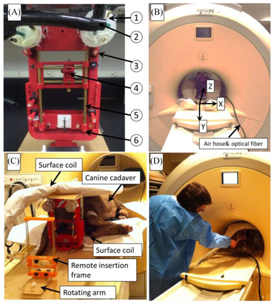
The custom designed robot aims to provide guidance for the laser catheter towards the target position. The robotic hardware setup consists of a robotic template guidance unit [see Fig. 1(A)] and a manual insertion unit. The hardware accessories include the pneumatic air hose, air supply, optical encoder fibers, Data Acquisition (DAQ) card and a pneumatic valve controller. To ensure the MR compliance of the robotic setup, the robotic template guidance unit and manual insertion mechanism were fabricated with MRI-conditional materials, such acrylonitrile butadiene styrene (ABS), acrylic and brass. The components powered by electricity, such as pneumatic valves, valve drivers, controller/DAQ, and optical encoder circuit, are placed outside the scanner room. Major component list to fabricate the robotic setup is shown in Table I. The detailed working principle of the custom designed motor and encoder unit has been discussed in a previous publication and will not be covered here in detail [25]. In the prior research, we introduced and tested the MRI-conditional robot. This paper will report the canine cadaver study result and OncoNav ablation monitoring.
Fig. 1.
(A) Prostate robot assembly. The detailed parts can be listed as follows: (1) custom designed pneumatic motor; (2) air hose bundle; (3) fiducial markers; (4) movable template; (5) supporting rod. (b) Prostate robot and volunteer inside the MR scanner. MRI coordinate frame is also shown. (C) Prostate robot and manual insertion mechanism for the canine cadaver study inside the MRI room. (D) User manually inserts the needle toward the target.
TABLE I.
Part Lists
| Item | Part name | Material | Quantity |
|---|---|---|---|
| 1 | Air motor | ABS | 2 |
| 2 | Air hose & optical fiber | Polyurethane & Acrylic | 4 |
| 3 | Fiducial marker | Gadolinium | 5 |
| 4 | Template | ABS | 1 |
| 5 | Guiding rod | Brass | 2 |
| 6 | Frame | ABS | 1 |
The robotic template guidance unit and the manual insertion mechanism are placed on top of an acrylic plate which can be rigidly affixed on the MRI table. The robot has the overall dimension of 130 mm × 180 mm while the workspace of the template is approximately 50 mm × 90 mm [see Fig. 1(B)]. The additional height is defined based on our previous in-gantry FLA and it ensures that the robot is able to reach the target despite the variations of patient size. The robot is able to manually rotate with respect to the y-axis (MR coordinate frame). This rotational DoF assists in the interventions where the targets are located directly behind the urethra.
B. Robot Working Principle
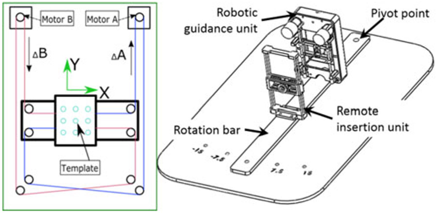
The robotic template guidance unit is constructed based on the CoreXY mechanism [26]. The template has two translational DoFs. Two custom designed MRI-conditional pneumatic motors with built-in optical encoders are mounted on the top of the CoreXY frame to actuate the template. As illustrated in Fig. 2(left), template position is coupled with the rotational position of the two motors, which can be expressed by the following equation
| (1) |
where ΔX and ΔY are the displacement of the template respectively, and ΔA and ΔB are the motor rotational position. Two sets of belts (red and blue lines in Fig. 2) transfer the motor rotational motion to template translational DoF. To move the template in the X-direction, the motor rotational motion should be the same in both direction and magnitude. Similarly, template Y-direction motion can be easily generated by driving the two motors in the opposite direction and with same magnitude. Moving one motor could generate the template diagonal movement, as illustrated by Eq. (1) when ΔA = 0.
Fig. 2.
Left: schematic diagram of the robot working principle. The red and blue lines indicate the timing belts on the motor output shaft. Right: assembly design of the proposed robotic hardware system mounted on a rotation bar that can be rotated manually in discrete angles ±7.5°, 15°.
The robot was designed to be mounted on a plate [see Fig. 2(right)] sitting in grooves along the sides of the MRI table. The base plate lies underneath the patient with the pivot point of the targeting assembly located under the patient’s prostate, defining the prostate as the remote center of motion (RCM). The RCM allows the robot and needle guide to be located at a different location from the pivot point while still rotating about the prostate, providing optimal coverage. The width of the robot permits the robot to face the patient’s perineum with the end effector less than 25 mm away from the perineum. The discrete DoF pivots the robot about the RCM, providing 0°, ±7.5° and ±15° relative to 0° parallel to the z-axis of the bore (see Fig. 1). This permits the targeting of tumors obstructed by the urethra and neurovascular bundles in systems without angulation. The guiding channel of the robotic guidance unit can be removed for sterilization or replacement by new guides for differing needle gauges or other tools.
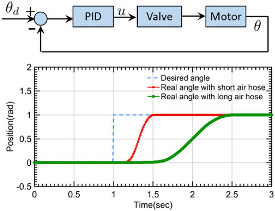
Motor feedback control is achieved via the proportional integral derivative (PID) algorithm, as can be seen in control block diagram of Fig. 3. The robot inverse kinematics ((1) calculates the desired motor motion (θd) according to the relationship between the moving frame current position and the desired position. The custom designed optical encoder feedback the real-time motor rotation position (θ) to the control loop. Based on the difference between θd and θ, PID controller calculates the desired voltage to power the pneumatic valves, where the valve (Festo MPYE-5-M5-010-B) regulates the pneumatic air flow supplied to the motor. In the experimental implementation, the motor is connected to the valves through the 8 meter air hoses (OD: 4 mm) and optical fibers. Unit set-point (1 rad) positioning test of the proposed motor was performed to evaluate the system delay and the accuracy performance. Long air hose (8 meters) could increase the motor response delay (0.37 s) compared to the motor coupled with a short air hose (length 0.2 m, response delay 0.14 s). However, the control accuracy performance is similar [see Fig. 3(bottom)] in both experimental conditions. The steady state error is less than 0.5% in both scenarios.
Fig. 3.
Top: motor control block diagram. Bottom: unit set-point positioning test for the motor accuracy performance evaluation.
C. Scanner-Robot Registration
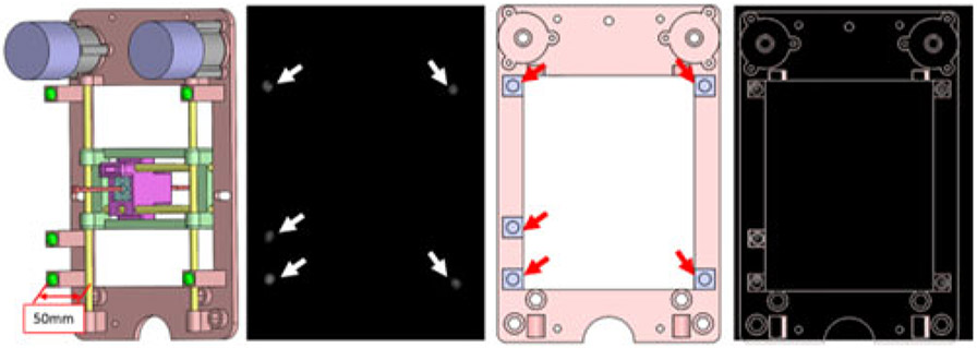
Registration is the process of calculating the rotation and translation matrix that relates the MRI coordinate frame scanner to the robot coordinate system. Five fiducial markers (D = 6 mm, Beekley Inc., Bristol, CT), which are visible in MR images, were precisely located at the predefined positions on the transverse plane of the robot. Prior to navigation and planning, high-resolution scanning was conducted to locate the fiducial markers’ positions in the MR coordinate system. As can be seen in Fig. 4(A), the fiducial markers were located 50 mm away from the inhomogeneous magnetic field caused by the brass guiding rod. Since the fiducial markers’ positions in the robot frame were predefined in the design process and no scaling occurred during the image acquisition process, registration can be accomplished with the rigid transformation method. The basic idea of this algorithm can be written in the following equation:
| (2) |
where A was the marker position in the robot frame, B was the marker position in the MR image frame, R was the rotation matrix, and t was the translation vector. In this study, we chose the Landmark-Least Squares Method to get the optimal R and t [27]. In this study, the number of fiducial markers was chosen to be five. Registration accuracy is increased with the number of the fiducial markers; however, this theoretical reduction comes at the expense of a more complicated design and larger physical dimension of the device. The fiducial markers in the MR frame and the robot can be seen in Fig. 4. The fiducial registration error was 0.4 mm.
Fig. 4.
From left to right: fiducial marker positions with respect to the robot frame with the offset of 50 mm perpendicular to the transverse plane of the robot to eliminate the effect of brass rod. Green balls show the five fiducial markers; MR image of the robot frame. White arrows: five fiducial markers within the MR image; front view of the prostate CAD model with fiducial markers labeled on the transverse plane. Red arrows: fiducial marker positions on the robot frame; MR image overlaid on the robot CAD design.
D. Iterative Treatment Planning
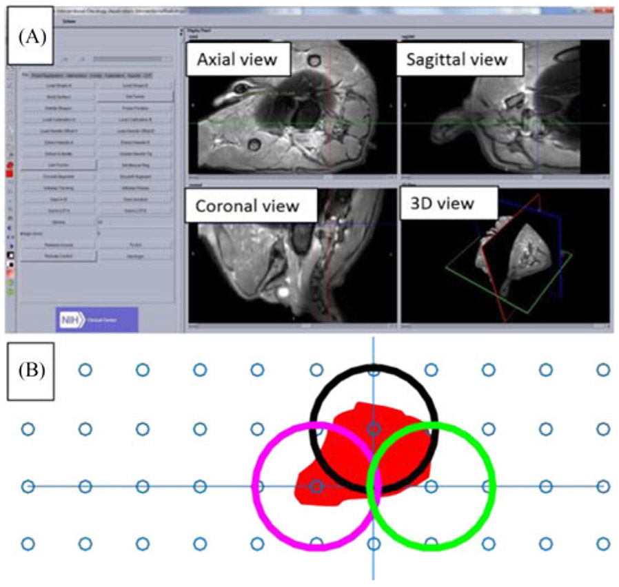
The physician performs the ablation procedure with the aid of custom designed OncoNav software [28]. At the beginning of the procedure, a T1-weighted (T1w) scan of the prostate and the fiducial markers are obtained to register the robot coordinate frame to the MRI scanner. A high-resolution T2-weighted (T2w) scan of the prostate is conducted to segment the tumor shape [see Fig. 5(A)]. Prior to ablation, the optimal treatment plan is calculated by minimizing the number of catheter insertions to cover the entire tumor volume [see Fig. 5(B)]. During the ablation process, the OncoNav software monitored temperature and calculated the real-time temperature map using the proton resonance frequency shift (PRFS) method [29]. Since the temperature map has little anatomical information, it is overlaid on the corresponding planning T2 weighted image, providing real-time verification of the treatment outcome.
Fig. 5.
(A) MR image reconstruction of the canine prostate using OncoNav: the left panel shows the function menu, and the right panel displays different views of the target organ. (B) Treatment planning with three ablation positions (circles) to cover the ablation zone.
The Visualase Laser Ablation System (Medtronic, Minneapolis, MN) was used in this study. The ablation system consists of a laser generator, an optical fiber that delivers laser from the control room into the scanner room, a water cooling system, a cooling catheter, a computer workstation, and a mechanical grid template (65 mm × 65 mm – holes are 5 mm apart) with embedded fiducials for registration. In this study, only the laser generator, optical fiber, and cooling catheter were used. The presented robotic positioning hardware and OncoNav software were adapted for surgical planning, catheter positioning, and navigation, as well as thermometry monitoring. Ablation size is limited to within 5–8 mm around the catheter, which requires multiple ablations to treat a large tumor. The laser ablation zone has the shape of an elongated ellipsoid, which can be written in the following equation:
| (3) |
where the semi-axes are of lengths p and q (normally q > p). The size of the ablation zone (x, y and z parameters in (3)) is a function of ablation time. Since the prostate does not have major blood vessels, the heat sink effect is small, making the ablation zone highly predictable. Noting that the estimated model is based on the position of the ablation probe, which could be deviated from the planned path. However, the ablation zone could be captured from the temperature map, which is more accurate and provides the intra-operative ablation outcome compared to the pre-planned ellipsoidal model. The temperature resolution is calculated based on the method described in [29], which can be written as
| (4) |
where Φ(t) is the MRI phase at the time of temperature measurement; Φ0 is the baseline MRI phase obtained before ablation. All of the parameters in the denominator are constants, with ϒ = 42.577 e6, α = −0.0094e – 6, B0 = 3 (3T MRI scanner in the proposed study), and TE = 8, which is sent to the navigation software via the real-time log file. The estimated ablation outcome through the intraoperative temperature map can be used to update the original treatment plan. The treatment plan is iteratively updated until all the residual tumor is treated. The target can be obtained by subtracting the estimated model from the preoperative tumor model after each round of ablation. The spatial information of the target can be derived from the T2w volumetric image and registered to the robot coordinate frame, which is used for robot joint space motion calculation. Once the needle is inserted to the desired position, another T2w scan is performed to verify its position with respect to target. The re-insertion of the needle is based on the judgement call of the physician.
E. Workflow Design of Robotic FLA
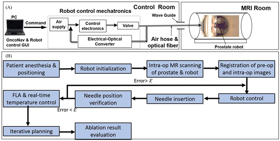
Fig. 6(A) shows the description of the experimental setup of the prostate robotic FLA system inside an MRI room. The robot remained inside the scanner throughout the procedure. The air hose connected to the pneumatic motor was passing through the waveguide to connect the air supply and motor controller, which was located outside the MRI scanner room. The pressurized air was regulated by 2 pneumatic valves, and supplied into the MRI room through the waveguide. The optical signal coming from the pneumatic motors was used to close the motor control loop; real-time temperature streamed into the OncoNav interface can be used to evaluate the intraoperative surgical outcome as well as iterative planning of the needle insertion.
Fig. 6.
(A) The experimental setup of the prostate robot in the MRI scanner room and control room. (B) Designed robotic FLA surgical workflow. ε is the predefined targeting error threshold based on the experience of our clinical collaborators; in this study, it was set to be 2 mm.
During the procedure, the subject was positioned within the MRI unit throughout the therapy in a lateral recumbent position. A T1w imaging volume containing the robotic platform and the prostate gland was chosen to get the position of the fiducial markers and the targets. Based on the fiducial markers’ positions in the MR image and robot frame, the transformation matrix was derived to map the points in the MR coordinate system to the robot coordinate frame. Having this high-resolution image, the robot inverse kinematics calculates the desired motion of each motor to make sure the center of the targeted tumor located inside the workspace of moving template. Then the surgeon manually inserted the needle to the target position after reviewing the needle insertion trajectory with OncoNav. The FLA was performed by delivering the laser energy to the target area. The real-time temperature of the position of the ablation catheter was monitored by the OncoNav software. Postoperative images were compared to the preoperative image to identify the ablated tissue within the tumors. The detailed workflow of the robotic-assisted FLA can be seen in Fig. 6(B).
III. Results and Discussions
A. Phantom Targeting Accuracy
In the proposed study, we evaluated the targeting accuracy in a commercially available anatomical prostate phantom (CIRS, VA, USA). Instead of simply inserting the needle to the desired position, we tested the accuracy performance in a more realistic approach. The simulated seed placement procedure with the help of the proposed system was used to quantify its performance. Target regions were selected in OncoNav treatment planning software, and the robot adjusted the needle guide accordingly. A needle and sheath were inserted to the target depth and the needle was subsequently removed. Plastic seeds (2 mm diameter × 10 mm length) were inserted through the sheath by the needle and lodged inside the phantom after an insertion approximately 50 mm deep [see Fig. 7(A) and (B)].
Fig. 7.
(A) and (B) Plastic seed distributed inside the prostate phantom. (C) MRI image of the seed.
Derived from MR images, the targeting errors of the seed placements (n = 10) had a mean of 0.9 mm and a standard deviation of 0.4 mm perpendicular to the needle guide. The error was defined as the distance between the actual seed position and the desired seed position. These errors were calculated from MR images with a voxel area of 1.18 mm × 1.18 mm for perpendicular error, and a 3.5 mm voxel depth for the error along the needle guide. The relatively large slice thickness contributed to some uncertainty with regards to insertion error, and measurements erred on the side of greater error to avoid over-reporting accuracy. The seed placement in the prostate phantom, with a spacing of ~10 mm between seeds, is shown in Table II. The obtained accuracy performance (0.9 ± 0.4 mm, max error = 1.6 mm, min error = 0.3mm) comparable with those robotic devices reported in [18]-[21], and [30]-[32]. The targeting performance of the proposed robotic system is better than the manual targeting approach, which has the mean and standard error of 6.5 mm and 3.5 mm respectively [33].
TABLE II.
Seed Placement Error in 10 Trials
| Trial | 1 | 2 | 3 | 4 | 5 | 6 | 7 | 8 | 9 | 10 |
|---|---|---|---|---|---|---|---|---|---|---|
| Error (mm) | 1.4 | 0.4 | 0.3 | 1.0 | 0.8 | 1.1 | 1.1 | 0.9 | 1.6 | 0.6 |
B. Phantom Ablation Test
A temperature-sensitive phantom model was used to validate the ablation performance of the proposed system in a Philips Achieva 3.0T TX MRI scanner. The phantom model was a homogenous volume of a low-temperature sensitive liposome (LTSL) co-loaded with an MRI contrast agent (Gd-HP-DO3A) [34], [35]. The detailed chemical constituents for the phantom fabrication can be seen in the Appendix.
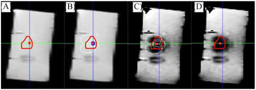
Preoperative and postoperative MR images (see Fig. 8) were analyzed in OncoNav to evaluate the virtual tumor volume and the actual ablated volume. Deviation of catheter insertion position from the desired target position was calculated from MR images as well. The catheter targeting error had a mean value of 1.7 mm and a standard deviation of 0.2 mm. With the proposed hardware and software system, the ablation procedure covered 100% of the virtual tumors and presented mild spillover from the ablation zone [see Fig. 8(D)].
Fig. 8.
(A) Sagittal view of the virtual tumor (the irregular red contour). (B) Multiple ablation regions (white ellipses) calculated by OncoNav. (C) Robot-assisted FLA based on the ablation plan. (D) Ablated area overlaid on top of the virtual tumor.
C. Canine Cadaver Trial Workflow Evaluation
The workflow evaluation of MR-guided robotic FLA was performed in three canine cadavers. The FLA was validated by creating the virtual tumors of the prostate and then ablating the targets within these three canine cadavers. The canine was placed on a paddle and immobilized at the MR bed. Two flexible image coils were placed with one underneath and another on top of the canine cadaver to provide high resolution of the target and fiducial markers for the purpose of registration. After the system setup preparation, the procedure was performed according to the aforementioned workflow. It is worth noting that each cadaver’s virtual tumor (size ≅ 5 × 5 × 5 mm3) was ablated with three administrations in order to cover the whole selected area of the prostate. The detailed time for the robotic FLA with OncoNav guidance was recorded and can be seen in Table I. The average procedure time for the canine cadaver studies was ~100 minutes. An advantage of the remote insertion capability of the proposed robotic FLA is that physician does not need to move the patient in and out of the MR scanner bore for performing imaging and interventional procedures. From Table III, we find that steps 1–5 (robot initialization and coordinate registration) occupied the majority of the procedure time (70/101 minutes) but it can be optimized through more practice with the robotic FLA. The canine studies show that the workflow of MRI-guided prostate FLA has the potential to shorten procedure time compared to the normal approach (100 minutes vs 2.5~4 hours [36]). Noting that the procedure time could be increased due to the sterility and anesthesia requirement in the real patient studies.
TABLE III.
Proposed Workflow for the Robotic FLA
| Step | Description | Time |
|---|---|---|
| 1. System Setup | Physical setup of robot and system in MR suite | 20 min. |
| 2. Subject Positioning | Aligning position of subject and robot | 10 min. |
| 3. Localizing Scan | Initial scan to determine subject/robot location | 5 min. |
| 4. Registration & Anatomy Scan | High-resolution scans of target anatomy and robot fiducials | 20 min. |
| 5. OncoNav Targeting | Identification of target anatomy and sectioning targets | 15 min. |
| 6. Robot Adjustment | Aligning robot guide with target point | 2 min. |
| 7. Trocar Insertion | Inserting trocar and sheath into patient | 2 min. |
| 8. Catheter Insertion | Removal of trocar, insertion of catheter | 2 min. |
| 9. Confirmation Scan | Confirming catheter location | 5 min. |
| 10. MR Thermometry | Tracking of tissue heating during ablation | 5 min. |
| 11. Repeat 6 through 10 | For new target or repositioning on current target | 15 min. |
| Total | 101 min |
D. Canine Cadaver Test
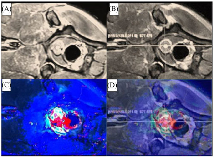
Robotic FLA was tested in three canine cadavers which weighed 35, 45, and 75 pounds. The virtual tumor of each canine was selected by the radiologist prior to the FLA. Each canine tumor requires three catheter insertions to ensure the ablation volume covered the desired target. The robotic FLA reached the average targeting accuracy of approximately 2 mm. Fig. 9 shows the pre-operative and post-operative image of the canine prostate MR images. It covers 100% of the desired ablation target. Fig. 10 shows the MR thermal image overlaid on the prostate image for the intraoperative ablation evaluation. The crosshair in Fig. 10(C) shows the ablated zone inside the prostate and the red area in Fig. 10(D) shows the ablated zone based on temperature monitoring. The MR thermal image is showed to estimate the ablation area, which is used for iterative planning of the ablation procedure. All of the virtual tumors were fully ablated in approximately 100 minutes.
Fig. 9.
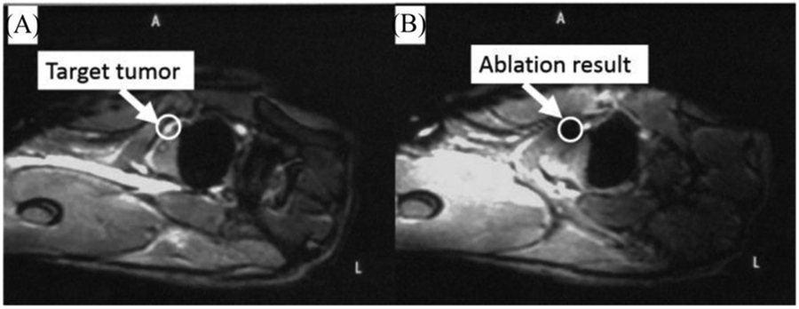
Pre-operative and post-operative MR image canine cadaver prostate. The white circle indicates the virtual tumor position.
Fig. 10.
(A) and (B) MR image of the canine prostate for visualization, target identification and insertion position selection respectively. (C) Intra-operative MR thermal image of the canine prostate. (D) MRI thermal image overlapped on the MRI image in OncoNav to enable the intra-operative evaluation of the ablation outcome.
IV. Conclusion
An MRI-conditional robotic needle guide and manually-driven remote insertion system were tested with the goal of improving available technology for prostate focal laser ablation. This study reports the state of hardware and software development and presents ablation testing results in canine cadavers. The needle guidance robot and manually-driven remote insertion system were tested as potential assistive technologies for MRI-guided and thermometry monitored FLA. Custom software, OncoNav, was used for robot-assisted prostate laser ablation with composite treatment planning. Composite treatment planning was performed in canine cadavers to quantify the coverage and efficacy of the ablated volume in an ex-vivo system. Robot-assisted MRI-guided FLA demonstrated advantages by providing accuracy in needle placement while supplying the ability to perform manually-driven remote insertions for reducing procedure time. Ablation of the target volumes was 100% covered with minimal damage to surrounding tissue. The system can potentially reduce the number of subject removals from the MRI scanner, enabling visual and haptic feedback during insertion and reducing the procedure time, which extrapolates to reduced costs in clinical practice. After being reviewed by Institutional Review Board (IRB) of NIH, potential patients will be recruited for in vivo trials for MRI-guided FLA.
Acknowledgment
NIH does not endorse or recommend any commercial products, processes, or services. The views and opinions of authors expressed herein do not necessarily state or reflect those of the U.S. Government nor does it constitute policy, endorsement or recommendation by the U.S. Government or National Institutes of Health (NIH). Please reference U.S. Code of Federal Regulations or U.S. Food and Drug Administration for further information.
This work was supported by the NIH Center for Interventional Oncology grant.
Appendix
An LTSL formulation containing lysolecithin (ThermoDox, Celsion Corp., Lawrenceville, NJ, USA) with a concentration of 1.8 mg doxorubicin/mL was utilized as the material for the phantom fabrication. Doxorubicin hydrochloride, zinc sulfate monohydrate (ZnSO4), phosphate buffer saline (PBS), potassium phosphate monobasic (KH2PO4), nitroblue tetrazolium (NBT), magnesium chloride (MgCl2), nicotinamide adenine dinucleotide phosphate (NADPH), and Trifluoroacetic acid were used from Sigma–Aldrich Corp. (Saint Louis, MO, USA).
Contributor Information
Yue Chen, College of Engineering, The University of Georgia, Athens, GA 30605 USA.
Sheng Xu, Center for Interventional Oncology, Department of Radiology and Imaging Sciences, National Institutes of Health..
Alexander Squires, College of Engineering, The University of Georgia..
Reza Seifabadi, Center for Interventional Oncology, Department of Radiology and Imaging Sciences, National Institutes of Health..
Ismail Baris Turkbey, Center for Interventional Oncology, Department of Radiology and Imaging Sciences, National Institutes of Health..
Peter A. Pinto, Center for Interventional Oncology, Department of Radiology and Imaging Sciences, National Institutes of Health.
Peter Choyke, Center for Interventional Oncology, Department of Radiology and Imaging Sciences, National Institutes of Health..
Bradford Wood, Center for Interventional Oncology, Department of Radiology and Imaging Sciences, National Institutes of Health..
Zion Tsz Ho Tse, College of Engineering, The University of Georgia..
References
- [1].Siegel R et al. , “Cancer statistics, 2017,” CA: Cancer J. Clin, vol. 67, pp. 7–30, 2017. [DOI] [PubMed] [Google Scholar]
- [2].Visualase Image-Guided Thermal Laser Ablation Technology in Urology. [Online]. Available: http://www.visualaseinc.com/prostate-focal-ablation/. Accessed on: Mar. 17, 2014.
- [3].Stoll M et al. , “Transfer of methods from radiotherapy planning to ablation planning with focus on uncertainties and robustness,” Biomedical Engineering/Biomedizinische Technik 57.SI-1 Track-C, 2012, pp. 901–904. [Google Scholar]
- [4].Lehmann KS et al. , “In vivo validation of a therapy planning system for laser-induced thermotherapy (LITT) of liver malignancies,” Int. J. Colorectal Dis, vol. 26, pp. 799–808, 2011. [DOI] [PubMed] [Google Scholar]
- [5].Cepek J et al. , “Treatment planning for prostate focal laser ablation in the face of needle placement uncertainty,” Med. Phys, vol. 41, 2014, Art. no. 013301. [DOI] [PubMed] [Google Scholar]
- [6].Cepek J et al. , “A system for MRI-guided transperineal delivery of needles to the prostate for focal therapy,” Med. Phys, vol. 40, 2013, Art. no. 012304. [DOI] [PubMed] [Google Scholar]
- [7].Cepek J et al. , “Mechatronic system for in-bore MRI-guided insertion of needles to the prostate: An in vivo needle guidance accuracy study,” J. Mag. Reson. Imag, vol. 42, pp. 48–55, 2014. [DOI] [PubMed] [Google Scholar]
- [8].Xu S et al. , “Real-time treatment iterative planning for composite ablations,” in Proc. 28th Int. Congr. Exhib. Comput. Assisted Radiol. Surg., Fukuoka, Japan, 2014, pp. 1–2. [Google Scholar]
- [9].Tse ZTH et al. , “A 3-DOF MR compatible device for magic angle related in vivo experiments,” ASME/IEEE Trans. Mechatronics, vol. 13, no. 3, pp. 316–324, June. 2008. [Google Scholar]
- [10].deSouza NM, “Magnetic resonance imaging guided breast biopsy using a frameless stereotactic technique,” Clin. Radiol, vol. 51, pp. 425–428, 1996. [DOI] [PubMed] [Google Scholar]
- [11].Hynynen K et al. , “MR imaging-guided focused ultrasound surgery of fibroadenomas in the breast: A feasibility study,” Radiology, vol. 219, pp. 176–185, April. 1, 2001. [DOI] [PubMed] [Google Scholar]
- [12].Larson BT et al. , “Design of an MRI-compatible robotic stereotactic device for minimally invasive interventions in the breast,” J. Biomech. Eng. Trans. ASME, vol. 126, pp. 458–465, August. 2004. [DOI] [PubMed] [Google Scholar]
- [13].Sutherland GR et al. , “NeuroArm: An MR compatible robot for micro-surgery,” Comput. Assisted Radiol. Surg, vol. 1256, pp. 504–508, 2003. [Google Scholar]
- [14].Hall WA et al. , “Brain biopsy using high-field strength interventional magnetic resonance imaging,” Neurosurg. Online, vol. 44, pp. 807–813, 1999. [DOI] [PubMed] [Google Scholar]
- [15].Hata N et al. , “Needle guiding robot for MR-guided microwave thermotherapy of liver tumor using motorized remote-center-of-motion constraint,” in Proc. 2005 IEEE Int. Conf. Robot. Autom., 2005, pp. 1652–1656. [Google Scholar]
- [16].Kim D et al. , “A new, compact MR-compatible surgical manipulator for minimally invasive liver surgery,” in Proc. 5th Int. Conf. Med. Image Comput. Comput.-Assisted Intervention, Tokyo, Japan, 2002, pp. 164–169. [Google Scholar]
- [17].Heywang SH, “MR imaging of the breast with Gd-DTPA: Use and limitations’,” Radiology, vol. 171, pp. 95–103, 1989. [DOI] [PubMed] [Google Scholar]
- [18].Stoianovici D et al. , “MRI-safe robot for endorectal prostate biopsy,” IEEE/ASME Trans. Mechatronics, vol. 19, no. 4, pp. 1289–1299, August. 2014. [DOI] [PMC free article] [PubMed] [Google Scholar]
- [19].Fischer GS et al. , “MRI-compatible pneumatic robot for transperineal prostate needle placement,” IEEE/ASME Trans. Mechatronics, vol. 13, no. 3, pp. 295–305, June. 2008. [DOI] [PMC free article] [PubMed] [Google Scholar]
- [20].Krieger A et al. , “An MRI-compatible robotic system with hybrid tracking for MRI-guided prostate intervention,” IEEE Trans. Biomed. Eng, vol. 58, no. 11, pp. 3049–3060, November. 2011. [DOI] [PMC free article] [PubMed] [Google Scholar]
- [21].Song S-E et al. , “Development of a pneumatic robot for MRI-guided transperineal prostate biopsy and brachytherapy: New approaches,” in Proc. 2010 IEEE Int. Conf. Robot. Autom., 2010, pp. 2580–2585. [DOI] [PMC free article] [PubMed] [Google Scholar]
- [22].Goldenberg AA et al. , “Robotic system for closed-bore MRI-guided prostatic interventions,” IEEE/ASME Trans. Mechatronics, vol. 13, no. 3, pp. 374–379, June. 2008. [Google Scholar]
- [23].Chen T and Lum PS, “Hand rehabilitation after stroke using a wearable, high DOF, spring powered exoskeleton,” in Proc. 2016 IEEE 38th Annu. Int. Conf. Eng. Med. Biol. Soc., 2016, pp. 578–581. [DOI] [PubMed] [Google Scholar]
- [24].Song S-E et al. , “Development and preliminary evaluation of a motorized needle guide template for MRI-guided targeted prostate biopsy,” IEEE Trans. Biomed. Eng, vol. 60, no. 11, pp. 3019–3027, November. 2013. [DOI] [PMC free article] [PubMed] [Google Scholar]
- [25].Chen Y et al. , “Robotic system for MRI-guided focal laser ablation in the prostate,” IEEE/ASME Trans. Mechatronics, vol. 22, no. 1, pp. 107–114, February. 2017. [DOI] [PMC free article] [PubMed] [Google Scholar]
- [26].Moyer IE, 2012. [Online]. Available: http://corexy.com/index.html [Google Scholar]
- [27].Boley DL et al. , “Robot localization from landmarks using recursive total least squares,” in Proc. IEEE Int. Conf. Robot. Autom. 1996, 1996, pp. 1381–1386. [Google Scholar]
- [28].Koethe Y et al. , “Accuracy and efficacy of percutaneous biopsy and ablation using robotic assistance under computed tomography guidance: A phantom study,” Eur. Radiol, vol. 24, pp. 723–730, 2014. [DOI] [PMC free article] [PubMed] [Google Scholar]
- [29].Yuan J et al. , “Towards fast and accurate temperature mapping with proton resonance frequency-based MR thermometry,” Quantitative Imag. Med. Surg, vol. 2, pp. 21–32, 2012. [DOI] [PMC free article] [PubMed] [Google Scholar]
- [30].Susil RC et al. , “System for prostate brachytherapy and biopsy in a standard 1.5 T MRI scanner,” Mag. Reson. Med, vol. 52, pp. 683–687, 2004. [DOI] [PMC free article] [PubMed] [Google Scholar]
- [31].Wei Z et al. , “Robot-assisted 3D-TRUS guided prostate brachytherapy: System integration and validation,” Med. Phys, vol. 31, pp. 539–548, 2004. [DOI] [PubMed] [Google Scholar]
- [32].Seifabadi R et al. , “Accuracy study of a robotic system for MRI-guided prostate needle placement,” Int. J. Med. Robot. Comput. Assisted Surg, vol. 9, pp. 305–316, 2013. [DOI] [PMC free article] [PubMed] [Google Scholar]
- [33].Blumenfeld P et al. , “Transperineal prostate biopsy under magnetic resonance image guidance: A needle placement accuracy study,” J. Mag. Reson. Imag, vol. 26, pp. 688–694, 2007. [DOI] [PubMed] [Google Scholar]
- [34].Ranjan A et al. , “Image-guided drug delivery with magnetic resonance guided high intensity focused ultrasound and temperature sensitive liposomes in a rabbit Vx2 tumor model,” J. Controlled Release, vol. 158, pp.487–494, 2012. [DOI] [PMC free article] [PubMed] [Google Scholar]
- [35].Negussie AH et al. , “Formulation and characterisation of magnetic resonance imageable thermally sensitive liposomes for use with magnetic resonance-guided high intensity focused ultrasound,” Int. J. Hyperthermia, vol. 27, pp. 140–155, 2011. [DOI] [PMC free article] [PubMed] [Google Scholar]
- [36].Lee T et al. , “Focal laser ablation for localized prostate cancer: Principles, clinical trials, and our initial experience,” Rev. Urol, vol. 16, pp. 55–66, 2014. [PMC free article] [PubMed] [Google Scholar]


