

Abstract
Passive energy storage and return (ESR) feet are current performance standard in lower limb prostheses. A recently developed semi-active variable-stiffness foot (VSF) prosthesis balances the simplicity of a passive ESR device with the adaptability of a powered design. The purpose of this study was to model and simulate the ESR properties of the VSF prosthesis. The ESR properties of the VSF were modeled as a lumped parameter overhung beam. The overhung length is variable, allowing the model to exhibit variable ESR stiffness. Foot-ground contact was modeled using sphere-to-plane contact models. Contact parameters were optimized to represent the geometry and dynamics of the VSF and its foam base. Static compression tests and gait were simulated. Simulation outcomes were compared to corresponding experimental data. Stiffness of the model matched that of the physical VSF (R2: 0.98, root-mean-squared error (RMSE): 1.37 N/mm). Model-predicted resultant ground reaction force (GRFR) matched well under optimized parameter conditions (R2: 0.98, RMSE: 5.3% body weight,) and unoptimized parameter conditions (R2: 0.90, mean RMSE: 13% body weight). Anterior–posterior center of pressure matched well with R2 > 0.94 and RMSE < 9.5% foot length in all conditions. The ESR properties of the VSF were accurately simulated under benchtop testing and dynamic gait conditions. These methods may be useful for predicting GRFR arising from gait with novel prostheses. Such data are useful to optimize prosthesis design parameters on a user-specific basis.
1 Introduction
Individuals with lower limb loss exhibit distinct gait characteristics, which may limit mobility and decrease quality of life. Those using lower limb prostheses may display gait asymmetry [1,2], elevated metabolic cost during locomotion [3], and a variety of psychological disorders including anxiety and depression [4]. Sustained prosthesis use may also induce overloading of intact joints and ultimately, musculoskeletal ailments [5]. Each of these issues may be attenuated by improving user specificity in the design characteristics of foot prostheses. However, the effects of foot prosthesis design parameters (e.g., stiffness) are not well characterized, and thus achieving meaningful improvements in gait has proven arduous [6,7]. In order to achieve improvements, a robust understanding of the relationships between anthropometry, gait mechanics, and prosthesis design is necessary.
One of the primary design goals of a lower limb prosthesis is to replace the coordinated energy absorption and generation properties of a lost limb. Passive energy storage and return (ESR) foot prostheses are the current standard for mimicking this functionality. However, the fixed stiffness behavior of these devices contrasts that of the healthy foot-ankle complex, which modulates its behavior in response to varied gait conditions (e.g., velocity and terrain) [8,9]. Glanzer and Adamczyk [10] recently developed a variable-stiffness foot (VSF) prosthesis designed with an actuated keel support fulcrum to semi-actively control sagittal forefoot stiffness and thereby adapt to different gait conditions with low power (Fig. 1). The ESR keel of the VSF is a composite leaf spring designed as an overhung beam, which modulates the supported length (l) via an actuated keel support fulcrum (B). The total beam length (L) is 229 mm, whereas the overhung length (a) is variable between 66 and 151 mm. By modulating overhung length, the VSF's forefoot is capable of exhibiting roughly a three-fold range of forefoot stiffness values (10–32 N/mm). The heel component of the VSF has a consistent linear stiffness of 65 N/mm. The VSF's fulcrum position is designed to be adjusted during swing phase, thus minimizing the power necessary for actuation. As such, the VSF behaves primarily as a passive ESR prosthesis, which can adapt stiffness in response to variable gait conditions.
Fig. 1.
![Overhung cantilever beam model of the VSF. The schematic illustrates keel length (L) pinned at A and simply supported at B, with a force applied at C. Overhung length (a) = L – l (supported length). Image reproduced with permission from Glanzer and Adamczyk [10].](https://cdn.ncbi.nlm.nih.gov/pmc/blobs/4523/8086177/4691ca162aba/bio-20-1237_074503_g001.jpg)
Overhung cantilever beam model of the VSF. The schematic illustrates keel length (L) pinned at A and simply supported at B, with a force applied at C. Overhung length (a) = L – l (supported length). Image reproduced with permission from Glanzer and Adamczyk [10].
Simulations based on computational models can be powerful tools for evaluating potential biomechanical interventions, such as the implementation of a novel ESR prosthesis. Recently, simulations have been used to aid in the iterative design process and improve user-specificity [11–13]. Inverse simulations provide the ability to estimate values that cannot be measured in vivo (e.g., socket-residual limb interface dynamics), whereas predictive simulations suggest hypotheses regarding how humans may interact with and adapt to new prosthetic devices.
Computational modeling has been used to investigate the effects of prosthesis alignment [14] and a biarticular clutched spring mechanism [15] on gait mechanics among persons with lower limb loss. However, these models do not account for the ESR properties of the prosthetic foot, thus limiting their ecological validity. Other studies, which did incorporate the force and torque contributions of ESR feet into gait models, focused on characterizing biomechanical and myophysiologic responses with prosthesis use, rather than validation of the prosthesis model [16,17]. While these studies made important progress toward investigating the relationship between anthropometry, gait mechanics, and prosthetic foot design, they had limited ability to verify simulation results in the context of experimental values. Due to these limitations, the use of simulations to inform the design of ESR foot prostheses has not been fully realized. The purpose of this study was to further couple experimental and simulation prosthesis data by modeling and validating the mechanical stiffness properties and resulting ground reaction forces of a semi-active VSF.
2 Methods
2.1 Model Design.
A computational model of the VSF was developed in Simscape Multibody (Mathworks, Inc., Natick, MA). The assembly, geometry, mass, and inertial properties were derived from SolidWorks (Dassault Systemes Inc., Waltham, MA). A reduced-order model of the VSF's variable-stiffness elastic keel was designed using the lumped parameter approach for approximating flexible body dynamics. This approach involved discretizing the continuous geometry of the keel into finite rigid segments coupled via revolute joints, springs, and dampers (Fig. 2). This simplification of the original state space of the continuous elastic keel system to finite dimensions allows the partial differential equations of the infinite-dimensional time–space states of the physical VSF to be represented by ordinary differential equations with a finite number of parameters.
Fig. 2.
![Modeled VSF, pylon, socket, and MTS. The MTS translates vertically, contacting the VSF 30 mm proximal to the end of the keel [10].](https://cdn.ncbi.nlm.nih.gov/pmc/blobs/4523/8086177/57445abaf291/bio-20-1237_074503_g002.jpg)
Modeled VSF, pylon, socket, and MTS. The MTS translates vertically, contacting the VSF 30 mm proximal to the end of the keel [10].
The keel of the VSF model was discretized into 16 segments (eight DoF). The most posterior segment is 66 mm in length, which matches the minimum possible fulcrum position. The rest of the keel consists of 11.64-mm segments for a total beam length of 229 mm (Fig. 2). The stiffness and damping values for the revolute joints were parameterized to represent the material properties of the VSF's G10/FR4 Garolite keel (flexural elastic modulus: 18.6 GPa, Poisson's ratio: 0.136). A matlab script controls continuous fulcrum position (i.e., variable stiffness). The VSF model was rigidly attached to a prosthetic pylon and socket via a pyramid adapter, as the device would be used in vivo. These connections were modeled as weld joints. Each segment is independently scalable, allowing the model to be integrated into an anatomically scaled computational gait model.
Foot-ground contact consists of 24 sphere-to-plane contact models [18] parameterized to represent the geometry and dynamics of the VSF's foam base. Each of these models estimates normal (Fn) and frictional (Ff) forces associated with the collision of a viscoelastic sphere (a massless spring and damper system) and a rigid plane (Fig. 3). The overall foot contact model was divided into five zones; the sphere-to-plane models were parameterized by zone (Fig. 3, Table 1). The heel of the VSF model is comprised of three zones; this choice was motivated by the sensitivity of contact parameters when few spheres are in contact with the walking plane (e.g., the heel of the foot early in stance phase). Contact parameters are less sensitive when many spheres are in contact with the walking plane (e.g., the midfoot and forefoot late in stance phase). The foam base of the physical VSF undergoes compression throughout stance phase. To account for these effects, a modified Kelvin-Voigt nonlinear spring and damper force law (Eq. (1)) was implemented to represent contact between the VSF and walking plane:
| (1) |
Fig. 3.
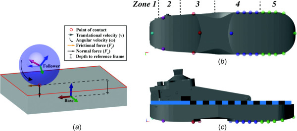
Schematic of a single sphere-to-plane contact model (A) and contact model plantar (B) and lateral (C) perspectives of the VSF sphere-to-plane contact models. Heel contact spheres vary in color by zone.
Table 1.
Summary of sphere-to-plane contact model parameters for the VSF
| Location | k (N/mm) | b (N⋅s/mm) | Penetration for full damping (mm) | Penetration exponent |
|---|---|---|---|---|
| Zone 1 | 90.16 | 3.525 | 7.474 | 297.7 |
| Zone 2 | 91.11 | 390.9 | 2.000 | 458.4 |
| Zone 3 | 18.01 | 292.9 | 2.900 | 3.152 |
| Zone 4 | 1003 | 252.1 | 0.765 | 0.977 |
| Zone 5 | 123.8 | 476.7 | 1.700 | 0.754 |
k: stiffness, b: damping.
Fn: normal force, k: contact stiffness, : penetration depth, n: penetration exponent, y: damping force scaling factor, : contact damping coefficient
The spring force increases exponentially as the sphere penetrates the contact plane. The damping force is multiplied by a scaling factor (y), which increases from zero to one as a polynomial as it approaches a user-defined value for full damping. Frictional force (Eq. (2)) is the product of the normal force and coefficient of friction (μ). A stick-slip friction law defines the transition between static (μstatic) and kinetic (μkinetic) coefficients of friction based on a velocity threshold (vthresh)
| (2) |
Ff: frictional force, : coefficient of friction, : velocity at point of contact, velocity threshold.
Static and kinetic coefficients of friction were set to 0.5 and 0.3 with a velocity threshold of 0.1 m/s. Resultant ground reaction force (GRFR) was derived by summing and low-pass filtering (fourth order Butterworth, ƒc: 40 Hz) the normal and frictional forces arising from each contact sphere.
In order to improve GRFR predictions, contact model parameterization was formulated as a least-squares optimization problem with the objective of minimizing the sum of squared errors between model-predicted and experimentally measured GRFR (see “Model Validation”). Initial parameter settings at the outset of the optimization were derived by increasing stiffness until the contact spheres were able to support the weight of the model. Initial damping coefficients (N⋅s/mm) were set to half the numerical value of stiffness (N/mm). Penetration exponents and penetration for full damping values were initialized at 1 and 1 mm, respectively. These initial values were used as inputs to the problem. Latin hypercube sampling (LHS) was applied to generate simulation scenarios with pseudo-random sets of parameters. The LHS approach is a method of stratified sampling, which divides parameter values into equal strata based on an assumed normal distribution and constrained by user-defined bounds. Random parameter values are sampled from within these strata to generate a simulation scenario with a pseudo-random set of parameters. The LHS technique effectively samples the search space, while providing the randomness required to explore the efficacy of a range of variable values to minimize the objective function. The objective function value of each iteration is compared to the previous iteration; the parameter scenario which best minimizes the objective is passed to the next iteration of the algorithm. The optimization algorithm proceeds for 100 iterations or until an objective function tolerance of 0.1 N is reached (i.e., convergence). If the optimization algorithm did not meet any of the termination criteria, the initial parameter values were updated using the results of the first run, and an additional run was initiated. Parameter tolerances were set to 0.001 (varying units) in order to avoid false minima.
2.2 Model Validation
2.2.1 Static Compression Testing.
The operational stiffness range of the physical VSF was determined through static compression testing (TestResources, Shakopee, MN) (Glanzer and Adamczyk 2018). Load was applied at a constant speed of 50 mm/min to a point 30 mm proximal to the anterior tip of the VSF (i.e., supported beam length = 199 mm). To validate the ESR properties of the VSF model, a simulated materials testing system (MTS) was developed in Simscape Multibody. The MTS simulator consists of a massless body, which translates vertically according to a user-defined time-position vector (Fig. 2). Simulated static compression tests were performed as in Glanzer and Adamczyk [10]. Contact was maintained throughout VSF deflection. Contact dynamics between the VSF and MTS were estimated using a sphere-to-sphere contact model. Stiffness (k) (Eq. (3)) was computed as the average slope of the load–displacement data for loads above 200 N.
| (3) |
Deformation for loads under 200 N was considered to arise primarily from foam compression, rather than keel displacement. Midrange keel displacement was also calculated for the VSF model as the displacement of the keel at 50% of the maximal load applied during the static compression test.
Static compression tests were simulated at five discrete fulcrum positions (66, 87, 108, 129, and 151 mm), which span the full continuous range of possible positions. These ascending fulcrum positions represent decreases in overhung length (a) depicted in Fig. 1, and therefore yield increases in endpoint stiffness. Simulation-derived values were compared to those from static compression tests of the physical VSF via coefficient of determination and root-mean-squared error (RMSE). Simulations were calculated in Simscape Multibody using the ode15 s solver profile with variable step size.
2.2.2 Gait Conditions.
Model-predicted GRFR was validated under two scenarios: static and dynamic gait conditions. For both validations, the VSF model was integrated into a seven-segment, 28-DoF anatomically scaled gait model of a subject with a unilateral transtibial amputation. Three-dimensional optical motion capture data (Optitrack, Natural Point, Inc., Corvallis, OR) of a male subject (181 cm, 78.0 kg) with a right-side transtibial amputation walking with the physical VSF were used as inputs to the model. Retroreflective marker coordinates from a static motion capture trial were used to estimate and scale limb dimensions for the pelvis, leg, intact shank, residual shank, and intact foot. Within the gait model, the residual shank was encapsulated in a prosthetic socket and welded to the pyramid adapter of the VSF model (Fig. 2). The interface between the prosthetic socket and residual limb was modeled as a high-stiffness 6-DoF bushing joint, similar to previous work by LaPrè et al. [14]. The rotational and translational stiffness as well as displacement and velocity constraints were designed according to previous gait experiments [19] and finite element analysis [20]. The mass and inertial properties of the lower limbs and pelvis were modeled as conical frusta and an ellipsoid, respectively. Segment masses were estimated according to De Leva [21].
For the static condition, the model was simulated with anatomically neutral joint angles for ten seconds. Model-predicted GRFR was averaged over the course of the trial and compared to the mass of the subject. Dynamic gait simulations were calculated based on experimental motion capture trials of the subject walking over ground between 1.0 and 1.2 m/s with the VSF under low, medium, and high stiffness configurations (fulcrum positions: 66, 108, and 151 mm). Three trials were collected for each stiffness configuration for a total of nine trials. Three-axis pelvis, hip, knee, and ankle angles were calculated from three-dimensional marker coordinate data [22,23] and used as inputs to drive the corresponding joints of the model. Motion at the socket–limb interface was considered to be passive based on the aforementioned velocity and displacement constraints. The pyramid adapter–pylon interface was assumed to be rigid.
Contact model-derived GRFR prediction was optimized for a single trial at the 66-mm fulcrum position. The GRFR error resulting from this trial represents the theoretical optimal performance of the comprehensive VSF-ground contact model. The transferability of the optimized parameter values was determined by simulating the two remaining low stiffness trials and the three remaining trials each for the medium and high stiffness configurations.
Joint kinematics and GRFR data were low-pass filtered (fourth order Butterworth: fc: 6 Hz and 40 Hz, respectively). Simulation and experimental GRFR were time locked and indexed to 0.25 s before and 0.25 s after stance phase. Including the brief period before and after stance phase provides insights regarding how the contact model behaves outside of stance phase and whether or not key gait events (e.g., heel strike and toe off) occur at similar time points in the simulated and experimental data. Resultant ground reaction force time series were resampled to 101 data points via cubic spline interpolation to allow for comparison between stance phases of differing lengths. Ensemble curves (mean ± SD) were generated for each condition. The impulse of GRFR was calculated to assess the simulation's ability to predict GRFR trajectory.
Anterior–posterior center of pressure (CoPAP) position was calculated as the weighted sum of each contact sphere's predicted force multiplied by its anterior–posterior position (x). Raw normal forces arising from each sphere during stance phase were low-pass filtered (fourth order Butterworth: fc: 40 Hz) and summed. Anterior–posterior CoP position was calculated across stance phase (Eq. (4))
| (4) |
CoPAP: anterior–posterior center of pressure position and xi: anterior–posterior coordinate of contact sphere.
The CoPAP time series data were low-pass filtered (fourth order Butterworth: fc: 6 Hz) and resampled to 101 data points via cubic spline interpolation to allow for comparison between stance phases of differing lengths. Joint kinematics, GRFR, and CoPAP data measured during experimental gait trials were compared to those derived from the simulations using coefficient of determination and RMSE.
3 Results
3.1 Static Compression Tests.
Simulated VSF stiffness effectively reproduced experimental stiffness across the five fulcrum configurations (R2 > 0.98, RMSE = 1.37 N/mm) (Fig. 4, Table 2). Simulated midrange displacement also matched well (R2 > 0.99) with small offset from experimental displacement in each condition (RMSE = 0.45 mm). Experimental load–displacement relationships were most linear in the 66 and 87 mm fulcrum configurations, as indicated by variance in the slope of the relationship. The stiffest three conditions exhibited curvilinear relationships. Simulated load–displacement data were linear in all conditions due to the linear spring and damper force parameters for the revolute joints in the lumped parameter keel model.
Fig. 4.
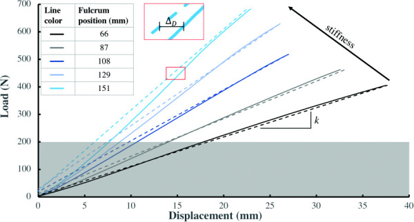
Load-displacement relationships for simulation (dashed) and experimental data (solid). Data are best fit ±95% confidence interval. Displacement offset (), example depicted with a bracket (|–|), is the difference between simulated and experimental midrange displacement (Eq. (3)). Fulcrum position is equivalent to supported length.
Table 2.
Comparative summary of experimental and simulated stiffness and midrange displacement
| Fulcrum position (mm) | Kexp (N/mm) | Ksim (N/mm) | Displacement offset (mm) |
|---|---|---|---|
| 66 | 10.43 ± 0.07 | 10.94 ± 0.00 | 0.02 |
| 87 | 14.17 ± 0.08 | 13.62 ± 0.00 | −0.46 |
| 108 | 19.45 ± 0.10 | 18.52 ± 0.00 | 0.23 |
| 129 | 24.83 ± 0.16 | 23.04 ± 0.00 | 0.32 |
| 151 | 31.59 ± 0.24 | 29.41 ± 0.00 | 0.79 |
Displacement (D) offset: . Data are mean ± SD.
Fulcrum position is equivalent to supported length.
3.2 Resultant Ground Reaction Force Predictions.
In the static condition, model-predicted subject mass was 2.6 ± 0.0% less than measured mass. In the dynamic conditions, simulated joint angles matched experimental joint angles well, but exhibited a small phase lag (mean RMSE: 1.9 ± 1.0 deg, mean R2: 0.98 ± 0.02). Simulated and experimental GRFR data agreed well in the time domain (Fig. 6). Amplitude discrepancies, quantified via RMSE, were least in low stiffness configuration and greatest in the high stiffness configuration. Coefficients of determination values were similar for the low and medium stiffness conditions and lower for the high stiffness condition. Impulse was similar in the low and high stiffness conditions and lower for the medium stiffness condition (Table 3).
Fig. 6.
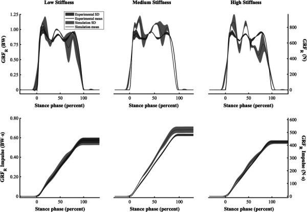
Ensemble curves for GRFR (top) and GRFR Impulse (bottom) for the low, medium, and high stiffness conditions (left, middle, and right)
Table 3.
Summary of GRFR, GRFR impulse, and COPAP comparison between simulated and experimental data
| GRFR | GRFR impulse | COPAP | ||||
|---|---|---|---|---|---|---|
| Stiffness configuration | R2 | RMSE (BW) | R2 | RMSE (BW⋅s) | R2 | RMSE (% FL) |
| Low | 0.93 ± 0.05 | 0.10 ± 0.04 | >0.99 ± 0.01 | 0.02 ± 0.01 | 0.95 ± 0.01 | 8.93 ± 0.99 |
| Medium | 0.92 ± 0.01 | 0.13 ± 0.02 | 0.96 ± 0.02 | 0.05 ± 0.01 | 0.94 ± 0.01 | 9.45 ± 0.92 |
| High | 0.87 ± 0.07 | 0.14 ± 0.07 | >0.99 ± 0.01 | 0.02 ± 0.01 | 0.97 ± 0.01 | 5.68 ± 1.39 |
BW: body weight, COPAP: anterior–posterior center of pressure, FL: foot length, data are mean ± SD.
Optimization of the single low stiffness trial resulted in a GRFR RMSE of 5.3% body weight (BW) and R2 of 0.98 across stance phase. Impulse also matched well (RMSE: 0.01 BW⋅s, R2 > 0.99) (Fig. 5). In the time domain, model-predicted heel contact preceded experimental heel contact by 0.02 s, resulting in a 0.02-s longer stance phase. Simulating the two additional low stiffness trials with the optimized contact parameters resulted in average RMSE and R2 values of 0.10 ± 0.05 BW and 0.93 ± 0.05 for GRFR and 0.02 ± 0.01 BW⋅s and >0.99 ± 0.01 for GRFR impulse (Fig. 6, Table 3).
Fig. 5.
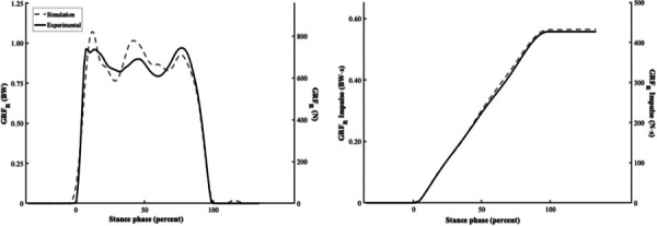
Optimized GRFR and GRFR impulse for a single trial at 66 mm fulcrum position
Experimental GRFR and GRFR impulse responses were similar in the time and amplitude domains across the three stiffness conditions (Fig. 6). On average, stance phase time was 0.05 ± 0.03 s longer in the simulations across the stiffness conditions. Time errors were least in the low stiffness condition and greatest in the high stiffness. Variability for GRFR was greatest during the first 25% of stance phase for all conditions. Variability for GRFR impulse was greatest near the end of stance phase. The ability of the contact parameters optimized for the low stiffness condition transferred well across the other two conditions, which is evident by the similar RMSE values for GRFR (Table 3). Resultant ground reaction force RMSE and R2 values were better in the medium stiffness configuration, whereas RMSE and R2 were better in the high stiffness condition for GRFR impulse. The medium stiffness condition demonstrated the least variability for the GRFR response, whereas the low and high stiffness conditions showed similarly low variability for GRFR impulse (Table 3).
Anterior–posterior CoP trajectory during stance phase was similar between simulated and experimental data (Fig. 7). Root mean squared errors were 8.9 ± 1.0, 9.5 ± 0.9, and 5.7 ± 1.4% foot length for the low, medium, and high stiffness conditions, respectively (Table 3). Simulated data correlated well with experimental data across all conditions. Coefficient of determination values were 0.95 ± 0.01, 0.94 ± 0.01, and 0.97 ± 0.01 for the low, medium, and high stiffness conditions.
Fig. 7.
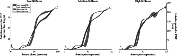
Ensemble curves for COPAP position for the low, medium, and high stiffness conditions (left, middle, and right)
4 Discussion
The goal of this study was to develop a reduced-order computational model of a semi-active variable-stiffness foot prosthesis. Results from simulated static compression tests showed good agreement with experimental data. These outcomes suggest that the variable-stiffness ESR properties of the VSF were modeled with high fidelity using a reduced-order lumped parameter approach for approximating flexible body dynamics. One of the goals of reduced-order modeling is to capture a structure's dynamic behavior in a computationally inexpensive way. A common benchmark for reduced-order models is the ability to simulate at or near real-time [24,25], which contrasts with more computationally expensive methods such as mesh-based finite element modeling. Including initialization time, static compression simulations computed 3.3 ± 0.8 times faster than real-time (i.e., the length of time required to complete the experimental static compression test) on computer with a four core 4.0 GHz processor. Initialization time, which includes model compiling and building, can be minimized using “accelerator” and “fast restart” modes in Simscape Multibody. Using these tools, simulations computed 39 ± 16 times faster than real-time. This computational efficiency is useful if the model is to be simulated iteratively, for example, in parameter optimization or machine learning frameworks.
The VSF is an ideal device for studying the effects of prosthesis stiffness on gait mechanics because it can readily exhibit a range of forefoot stiffness values, thereby eliminating the need to purchase or manufacture multiple prostheses as in Refs. [26–28]. In doing so, this also eliminates confounding variables that accompany a foot-switching experimental design, such as mismatched or out-of-order stiffness from foot prostheses of different categories. The VSF can also modulate stiffness along a continuous scale, which provides improved resolution compared to the typical discrete stiffness options available for fully passive designs. The range of forefoot stiffness values exhibited by the physical VSF and captured by the VSF model represent a range of stiffness values available in many commercially available prosthetic feet [29,30]. Accurate characterization of this range is important, should this model be used to inform the design and/or prescription of prosthetic feet. Further, this model can be easily reparameterized to exhibit a different range of stiffness values, which could aid in the selection of keel dimensions or material properties to meet design goals. Two primary limitations are present for the static compression testing simulations. Experimental load–displacement data were only available for positive loading conditions, and thus a comparison of the model's hysteresis behavior was not possible. Similarly, experimental data were only available for the 50 mm/min loading rate. A robust characterization of the VSF's stiffness behavior under a range of higher loading rates would likely improve the model's behavior under dynamic conditions. Experimental load–displacement data could also be influenced by imperfections in maintaining a constant contact point with the prosthesis. Results of this study are difficult to compare to previous work, as there is a paucity of previous research that evaluated simulated prosthesis dynamics compared to mechanical testing data of a physical prosthesis under multiple conditions. However, errors exhibited by this model are similar to those reported in Tryggvason et al. [13], who compared the angular stiffness response of a finite element foot prosthesis model to data from mechanical tests [13].
Under dynamic gait conditions, simulated joint angles agreed well with experimental values, indicating that the model is numerically stable when actuated by joint kinematics measured during gait with the VSF. Joint angles were strongly correlated, but exhibited a small phase lag, possibly due to ordinary differential equation solver settings and numerical integration. This phase lag may be also be present in the kinetic data, but masked by the larger inherent variability of the simulated GRFR. Total simulation times were 8.95 ± 3.92, 12.7 ± 0.67, and 46.2 ± 1.19 times slower than real-time for the low, medium, and high stiffness configurations, respectively. Execution times were 3.12 ± 0.10, 3.40 ± 0.67, and 38.4 ± 1.19 times slower than real-time. Increased execution times for the stiff conditions may reflect the need for small time-steps in solving a rapidly evolving, stiff differential equation.
Optimization of the GRFR for the low stiffness configuration achieved a RMSE of 5.3% BW and R2 of 0.98. These values are similar to those reported in previous biomechanical contact modeling work [31–33]. However, those studies focused on quantification of foot-ground contact during gait for individuals with intact limbs. Direct comparison of these data was limited to work in intact limb biomechanical modeling due to a lack of studies reporting validation data for prosthesis-ground contact modeling in gait biomechanics. The strong correlation and low error for GRFR impulse indicate that the contact model is able to predict the shape and trajectory of the GRFR arising from gait kinematics. Accurate predictions of GRFR impulse are important for capturing whole-body energetics throughout gait. The concomitant agreement for both kinematics and kinetics further suggests that these methods are viable for simulating whole-body energetics during gait.
The transferability of the optimized contact model parameters from the low stiffness condition was assessed by simulating two additional low stiffness trials and three trials each with medium and high stiffness configurations. Compared to the optimized trial, simulation-derived GRFR predictions did not perform as well in the unoptimized trials. Mean GRFR RMSE and R2 were 12.7 ± 1.44% BW and 0.91 ± 0.02 for the remaining low stiffness trials. These values were similar for the medium and low stiffness trials (Table 3). The impulse of these data matched well across the unoptimized trials (RMSE: 0.03 ± 0.02 BW⋅s, R2: 0.98 ± 0.01). Variability of the model's performance was similar across the unoptimized conditions for all outcome measures. It is possible that the contact model parameters were over-fitted to the specific conditions of a single trial, resulting in decreased generalizability. Future work should assess the balance between optimization specificity and generalizability.
The amplitude and shape of experimental GRFR waveforms were similar across the three stiffness conditions. However, stance phase times did vary by condition for the subject tested. The medium stiffness condition resulted in the longest stance phase time (0.79 ± 0.01 s), high stiffness resulted in the shortest (0.71 ± 0.02 s), and low stiffness (0.73 ± 0.02 s) was in the middle. The same pattern was present in the simulated data, although stance phase times were 0.05 ± 0.03 s longer on average compared to the experimental data. Stance phase times derived from simulations were correlated with experimental times (R2 = 0.65). More data are necessary to discern the strength, repeatability, and significance of these relationships.
Simulated CoPAP values agreed well with experimental values. The RMSE values achieved using this model were similar to those reported in previous work involving subject-specific biomechanical contact modeling for individuals with intact limbs [34]. Accurate mapping of CoPAP throughout stance phase is vital for simulating the effects of variable prosthesis stiffness on joint forces and moments during gait. Errors in model-predicted CoPAP may be reduced by increasing the density of contact spheres distributed on the plantar surface of the foot, which would improve the resolution of CoPAP predictions. However, this would likely result in increased execution time for simulations and also increase complexity of the contact parameter optimization problem.
The present data show promise for predicting GRFR arising from a semi-active VSF prosthesis. These methods may be applied to the design and prescription of lower limb prostheses and forward dynamics simulations in robotics and biomechanics. Within biomechanics, future work could integrate the VSF model into a gait model of an individual with lower limb loss. Gait simulations could be formulated as an optimal control problem in which prosthesis stiffness is tuned to minimize a biomechanical cost function such as joint loading or metabolic cost. Evaluating these effects within a simulation-based framework rather than traditional in vivo experimentation minimizes risk and time spent by the user. Further, a broad spectrum of prosthesis design parameters could be modeled and simulated without the need to manufacture multiple devices or the costs associated with doing so.
Further optimization of the VSF-ground contact model may be necessary for simulation scenarios with error tolerances less than 12% BW. Similar improvements may be required if the mean difference between simulation conditions is less than the error of the model. Reducing error in model-predicted GRFR may be accomplished by evaluating the objective function under a variety of conditions and choosing the parameter set that achieves the best minimization across several conditions. A deformable contact model, such as presented in Jackson et al. [34], may also be a viable means of representing foam deformation throughout stance phase and thus reducing error.
These methods assume accurate estimation of segment length, joint centers, and joint angles, which were derived from marker-based motion capture data. Each of these metrics likely suffers from small errors due to marker placement, localization, and coordinate system design. Such errors would contribute to decrements in contact model performance. Characterizing the model's sensitivity to varied joint kinematics is possible within the present simulation paradigm. However, this analysis was not performed due to lack of experimental gait data necessary to quantify accuracy of those simulations. The components and joints of the prosthetic limb were also modeled as rigid, which may not be completely accurate to represent the physical limb. This discrepancy would manifest as small differences in kinematics and energy transfer between the components of the prosthetic limb. Nevertheless, simulated motions were consistent with experimental data of subjects walking with the VSF and other previously reported data of spatiotemporal gait patterns among persons with lower limb loss [35,36]. Another limitation is inherent to the reduced-order design of the lumped parameter VSF keel, which constrains keel motion to the sagittal plane. While this design is computationally efficient compared to more robust finite element models, it fails to account for small torsional keel motions that would be possible under ecological gait conditions with the physical VSF.
5 Conclusions
This study demonstrates that the ESR properties of a semi-active VSF can be modeled with high fidelity. Foot-ground contact models were used to estimate GRFR with 5.3% BW error in an optimized gait trial, which translated to mean errors of 13% for unoptimized trials. The contact models also predicted COPAP with mean error of 9.3% foot length. This model performance may be sufficient for gait simulations among persons with lower limb loss. Such simulations may be used to aid in the prosthesis design and prescription process in order to improve user mobility. These methods may also be helpful to identify other important prosthesis design parameters, which can be modified to optimize gait. Further contact model optimization and error reduction may be required for simulation-based comparisons of varied prosthesis stiffness, where differences in GRFR magnitude may be nuanced.
Acknowledgment
The authors would like to thank Evan Glanzer for his work in developing and testing the variable-stiffness foot and Terry Denery for his intellectual contributions in optimizing the contact model.
Funding Data
Lokey Doctoral Science Fellowship (MAM) (Funder ID: 10.13039/100011348).
Eunice Kennedy Shriver National Institute of Child Health and Human Development (Grant No. HD074424 (PGA); Funder ID: 10.13039/100009633).
Nomenclature
Abbreviations
- a =
overhung length, mm
- b =
damping coefficient, N⋅s/mm
- B =
support fulcrum position, mm
- D =
displacement, mm
- F =
force, N
- k =
linear stiffness, N/mm
- l =
supported length, mm
- L =
total beam length, mm
- n =
penetration exponent
- R2 =
coefficient of determination
- y =
scaling factor
- =
penetration depth, mm
- =
penetration velocity, mm/s
- μ =
coefficient of friction
- v =
linear velocity
- ω =
angular velocity, rad/s
Superscripts and Subscripts
- CoPAP =
anterior–posterior (center of pressure)
- Dsim =
simulation (displacement)
- Dexp =
experimental (displacement)
- Ff =
frictional force, N
- Fn =
normal force, N
- GRFR =
resultant ground reaction force, N
- ksim =
simulation (stiffness), N/mm
- kexp =
experimental (stiffness), N/mm
- vpoc =
linear velocity at point of contact, mm/s
- vthreshold =
linear velocity threshold, m/s
- μkinetic =
coefficient of kinetic friction
- μstatic =
coefficient of static friction
Acronyms
- BW =
body weight; M*g
- CoP =
center of pressure
- DoF =
degrees of freedom
- ESR =
energy storage and return
- GRFR =
resultant ground reaction force, N;
- LHS =
Latin hypercube sampling
- MTS =
material testing system
- ode15 s =
ordinary differential Eq. (15) solver
- RMSE =
root mean square error;
- SD =
standard deviation
- VSF =
variable stiffness foot
References
- [1]. Schaarschmidt, M. , Lipfert, S. W. , Meier-Gratz, C. , Scholle, H. C. , and Seyfarth, A. , 2012, “ Functional Gait Asymmetry of Unilateral Transfemoral Amputees,” Hum. Mov. Sci., 31(4), pp. 907–917. 10.1016/j.humov.2011.09.004 [DOI] [PubMed] [Google Scholar]
- [2]. Sanderson, D. J. , and Martin, P. E. , 1997, “ Lower Extremity Kinematic and Kinetic Adaptations in Unilateral Below-Knee Amputees During Walking,” Gait Posture, 6(2), pp. 126–136. 10.1016/S0966-6362(97)01112-0 [DOI] [Google Scholar]
- [3]. van Schaik, L. , Geertzen, J. H. , Dijkstra, P. U. , and Dekker, R. , 2019, “ Metabolic Costs of Activities of Daily Living in Subjects With Lower Limb Amputation: A Systematic Review and Meta-Analysis. Article Submitted for Publication,” PLoS One, 14(3), p. e0213256. 10.1371/journal.pone.0213256 [DOI] [PMC free article] [PubMed] [Google Scholar]
- [4]. Mckechnie, P. S. , and John, A. , 2014, “ Anxiety and Depression Following Traumatic Limb Amputation: A Systematic Review,” Injury, 45(12), pp. 1859–66. 10.1016/j.injury.2014.09.015 [DOI] [PubMed] [Google Scholar]
- [5]. Gailey, R. , Allen, K. , Castles, J. , Kucharik, J. , and Roeder, M. , 2008, “ Review of Secondary Physical Conditions Associated With Lower-Limb Amputation and Long-Term Prosthesis Use,” JRRD, 45(1), pp. 15–30. 10.1682/JRRD.2006.11.0147 [DOI] [PubMed] [Google Scholar]
- [6]. Casillas, J. M. , Dulieu, V. , Cohen, M. , Marcer, I. , and Didier, J. P. , 1995, “ Bioenergetic Comparison of a New Energy-Storing Foot and SACH Foot in Traumatic Below-Knee Vascular Amputations,” Arch. Phys. Med. Rehabil., 76(1), pp. 39–44. 10.1016/S0003-9993(95)80040-9 [DOI] [PubMed] [Google Scholar]
- [7]. Postema, K. , Hermens, H. J. , De Vries, J. , Koopman, H. F. J. M. , and Eisma, W. H. , 1997, “ Energy Storage and Release of Prosthetic Feet Part 1: Biomechanical Analysis Related to User Benefits,” Prosthet. Orthot. Int., 21(1), pp. 17–27. 10.3109/03093649709164526 [DOI] [PubMed] [Google Scholar]
- [8]. Farris, D. J. , and Sawicki, G. S. , 2012, “ The Mechanics and Energetics of Human Walking and Running: A Joint Level Perspective,” J. R. Soc. Interface, 9(66), pp. 110–18. 10.1098/rsif.2011.0182 [DOI] [PMC free article] [PubMed] [Google Scholar]
- [9]. Winter, D. A. , 1983, “ Energy Generation and Absorption at the Ankle and Knee During Fast, Natural, and Slow Cadences,” Clin. Orthop. Relat. Res., 175, pp. 147–154.https://pubmed.ncbi.nlm.nih.gov/6839580/ [PubMed] [Google Scholar]
- [10]. Glanzer, E. M. , and Adamczyk, P. G. , 2018, “ Design and Validation of a Semi-Active Variable Stiffness Foot Prosthesis,” IEEE Trans. Neural Syst. Rehabil. Eng., 26(12), pp. 2351–2359. 10.1109/TNSRE.2018.2877962 [DOI] [PMC free article] [PubMed] [Google Scholar]
- [11]. Fey, N. P. , Klute, G. K. , and Neptune, R. R. , 2013, “ Altering Prosthetic Foot Stiffness Influences Foot and Muscle Function During Below-Knee Amputee Walking: A Modeling and Simulation Analysis,” J. Biomech., 46(4), pp. 637–644. 10.1016/j.jbiomech.2012.11.051 [DOI] [PubMed] [Google Scholar]
- [12]. Strbac, M. , and Popovic, D. , 2012, “ Software Tool for the Prosthetic Foot Modeling and Stiffness Optimization,” Comput. Math. Methods Med., 2012, pp. 1–8. 10.1155/2012/421796 [DOI] [PMC free article] [PubMed] [Google Scholar]
- [13]. Tryggvason, H. , Starker, F. , Lecomte, C. , and Jonsdottir, F. , 2020, “ Use of Dynamic FEA for Design Modification and Energy Analysis of a Variable Stiffness Prosthetic Foot,” Appl. Sci., 10(2), p. 650. 10.3390/app10020650 [DOI] [Google Scholar]
- [14]. Laprè, A. K. , Umberger, B. R. , and Sup, F. , 2014, “ Simulation of a Powered Ankle Prosthesis With Dynamic Joint Alignment,” 36th Annual International Conference of the IEEE Engineering in Medicine and Biology Society, EMBC 2014, Chicago, IL, Aug. 26–30, pp. 1618–1621. 10.1109/EMBC.2014.6943914 [DOI] [PubMed] [Google Scholar]
- [15]. Willson, A. M. , Richburg, C. A. , Czerniecki, J. , Steele, K. M. , and Aubin, P. M. , 2020, “ Design and Development of a Quasi-Passive Transtibial Biarticular Prosthesis to Replicate Gastrocnemius Function in Walking,” ASME J. Med. Devices, 14(2), p. 025001. 10.1115/1.4045879 [DOI] [PMC free article] [PubMed] [Google Scholar]
- [16]. Fey, N. P. , Klute, G. K. , and Neptune, R. R. , 2012, “ Optimization of Prosthetic Foot Stiffness to Reduce Metabolic Cost and Intact Knee Loading During Below-Knee Amputee Walking: A Theoretical Study,” ASME J. Biomech. Eng., 134(11), p. 111005. 10.1115/1.4007824 [DOI] [PMC free article] [PubMed] [Google Scholar]
- [17]. Russel, E. E. , and Miller, R. H. , 2018, “ Maintenance of Muscle Strength Retains a Normal Metabolic Cost in Simulated Walking After Transtibial Limb Loss,” PLoS One, 13(1), p. e0191310. 10.1371/journal.pone.0191310 [DOI] [PMC free article] [PubMed] [Google Scholar]
- [18]. Miller, S. , 2020, “ Simscape Multibody Contact Forces Library,” MathWorks, Natick, MA, accessed Mar. 25, 2021, https://www.mathworks.com/matlabcentral/fileexchange/47417-simscape-multibody-contact-forces-library
- [19]. LaPrè, A. K. , Price, M. A. , Wedge, R. D. , Umberger, B. R. , and Sup, F. C. , 2018, “ Approach for Gait Analysis in Persons With Limb Loss Including Residuum and Prosthesis Socket Dynamics,” Int. J. Numer. Method. Biomed. Eng., 34(4), p. e2936. 10.1002/cnm.2936 [DOI] [PubMed] [Google Scholar]
- [20]. Jia, X. , Zhang, M. , and Lee, W. C. C. , 2004, “ Load Transfer Mechanics Between Trans-Tibial Prosthetic Socket and Residual Limb—Dynamic Effects,” J. Biomech., 37(9), pp. 1371–77. 10.1016/j.jbiomech.2003.12.024 [DOI] [PubMed] [Google Scholar]
- [21]. De Leva, P. , 1996, “ Adjustments to Zatsiorsky-Seluyanov's Segment Inertia Parameters,” J. Biomech., 29(9), pp. 1223–1230. 10.1016/0021-9290(95)00178-6 [DOI] [PubMed] [Google Scholar]
- [22]. Wu, G. , Siegler, S. , Allard, P. , Kirtley, C. , Leardini, A. , Rosenbaum, D. , Whittle, M. , D'Lima, D. D. , Cristofolini, L. , Witte, H. , Schmid, O. , and Stokes, I. , 2002, “ ISB Recommendation on Definitions of Joint Coordinate System of Various Joints for the Reporting of Human Joint Motion - Part I: Ankle, Hip, and Spine,” J. Biomech., 35(4), pp. 543–548. 10.1016/S0021-9290(01)00222-6 [DOI] [PubMed] [Google Scholar]
- [23]. Grood, E. S. , and Suntay, W. J. , 1983, “ A Joint Coordinate System for the Clinical Description of Three-Dimensional Motions: Application to the Knee,” ASME J. Biomech. Eng., 105(2), pp. 136–144. 10.1115/1.3138397 [DOI] [PubMed] [Google Scholar]
- [24]. Thakallapelli, A. , Ghosh, S. , and Kamalasadan, S. , 2016, “ Real-Time Frequency Based Reduced Order Modeling of Large Power Grid,” IEEE Power and Energy Society General Meeting, IEEE Computer Society, Boston, MA, July 17–21, pp. 1–5. 10.1109/PESGM.2016.7741877 [DOI] [Google Scholar]
- [25]. Kikuchi, R. , Misaka, T. , and Obayashi, S. , 2016, “ International Journal of Computational Fluid Dynamics Real-Time Prediction of Unsteady Flow Based on POD Reduced-Order Model and Particle Filter,” Int. J. Comut. Fluid Dyn., 30(4), pp. 285–306. 10.1080/10618562.2016.1198782 [DOI] [Google Scholar]
- [26]. Fey, N. P. , Klute, G. K. , and Neptune, R. R. , 2011, “ The Influence of Energy Storage and Return Foot Stiffness on Walking Mechanics and Muscle Activity in Below-Knee Amputees,” Clin. Biomech., 26(10), pp. 1025–1032. 10.1016/j.clinbiomech.2011.06.007 [DOI] [PubMed] [Google Scholar]
- [27]. Zelik, K. E. , Collins, S. H. , Adamczyk, P. G. , Segal, A. D. , Klute, G. K. , Morgenroth, D. C. , Hahn, M. E. , Orendurff, M. S. , Czerniecki, J. M. , and Kuo, A. D. , 2011, “ Systematic Variation of Prosthetic Foot Spring Affects Center-of-Mass Mechanics and Metabolic Cost During Walking,” IEEE Trans. Neural Syst. Rehabil. Eng., 19(4), pp. 411–419. 10.1109/TNSRE.2011.2159018 [DOI] [PMC free article] [PubMed] [Google Scholar]
- [28]. Jin, L. , Roland, M. , Hahn, M. E. , and Adamczyk, P. G. , 2016, “ The Effect of High-and Low-Damping Prosthetic Foot Structures on Knee Loading in the Uninvolved Limb Across Different Walking Speeds,” J. Appl. Biomech., 32(3), pp. 233–240. 10.1123/jab.2015-0143 [DOI] [PubMed] [Google Scholar]
- [29]. Webber, C. M. , and Kaufman, K. , 2017, “ Instantaneous Stiffness and Hysteresis of Dynamic Elastic Response Prosthetic Feet,” Prosthet. Orthot. Int., 41(5), pp. 463–468. 10.1177/0309364616683980 [DOI] [PubMed] [Google Scholar]
- [30]. Womac, N. D. , Neptune, R. R. , and Klute, G. K. , 2019, “ Stiffness and Energy Storage Characteristics of Energy Storage and Return Prosthetic Feet,” Prosthet. Orthot. Int., 43(3), pp. 266–275. 10.1177/0309364618823127 [DOI] [PubMed] [Google Scholar]
- [31]. Van Hulle, R. , Schwartz, C. , Denoël, V. , Croisier, J.-L. , Forthomme, B. , and Brüls, O. , 2020, “ A Foot/Ground Contact Model for Biomechanical Inverse Dynamics Analysis,” J. Biomech., 100(2020). [DOI] [PubMed] [Google Scholar]
- [32]. Lopes, D. S. , Neptune, R. R. , Ambrósio, J. A. , and Silva, M. T. , 2015, “ A Superellipsoid-Plane Model for Simulating Foot-Ground Contact During Human Gait,” Comput. Methods Biomech. Biomed. Eng., 19(9), pp. 954–963. 10.1080/10255842.2015.1081181 [DOI] [PubMed] [Google Scholar]
- [33]. Brown, P. , and McPhee, J. , 2018, “ A 3D Ellipsoidal Volumetric Foot–Ground Contact Model for Forward Dynamics,” Multibody Syst. Dyn., 42(4), pp. 447–467. 10.1007/s11044-017-9605-4 [DOI] [Google Scholar]
- [34]. Jackson, J. N. , Hass, C. J. , and Fregly, B. J. , 2016, “ Development of a Subject-Specific Foot-Ground Contact Model for Walking,” ASME J. Biomech. Eng., 138(9), p. 091002. 10.1115/1.4034060 [DOI] [PMC free article] [PubMed] [Google Scholar]
- [35]. Winter, D. A. , and Sienko, S. E. , 1988, “ Biomechanics of Below-Knee Amputee Gait,” J. Biomech., 21(5), pp. 361–367. 10.1016/0021-9290(88)90142-X [DOI] [PubMed] [Google Scholar]
- [36]. Su, P.-F. , Gard, S. A. , Lipschutz, R. D. , and Kuiken, T. A. , 2008, “ Differences in Gait Characteristics Between Persons With Bilateral Transtibial Amputations, Due to Peripheral Vascular Disease and Trauma, and Able-Bodied Ambulators,” Arch. Phy.s Med. Rehabil., 89(7), pp. 1386–1394. 10.1016/j.apmr.2007.10.050 [DOI] [PMC free article] [PubMed] [Google Scholar]