Abstract
This work presents a long-range and extended depth-of-focus optical coherence tomography (OCT) system using a Bessel-like beam (BLB) as a visual feedback system during laser osteotomy. We used a swept-source OCT system (λc = 1310 nm) with an imaging range of 26.2 mm in the air, integrated with a high energy microsecond Er:YAG laser operating at 2.94 µm. We demonstrated that the self-healing characteristics of the BLB could reduce the imaging artifacts that may arise during real-time monitoring of laser ablation. Furthermore, the feasibility of using long-range OCT to monitor a deep laser-induced incision is demonstrated.
1. Introduction
Osteotomy is a surgical intervention involving cutting, etching, shaving, and/or chipping of the bone. The most common osteotomy methods apply mechanical stress to the surface of the bone, using saws, drills, and chisels [1,2]. In addition to practical difficulties, mechanical trauma, broad cuts, excessive heat generation, and bacterial contamination are among the main risks associated with using conventional instruments for osteotomy [3]. Laser technology was introduced to overcome the limits of the mechanical tool used during surgery. Laser osteotomy is a contactless and potentially minimally invasive technology for bone surgery, providing freedom along with the cutting geometry and high precision [4–8]. However, one technical drawback of using lasers for osteotomy is the lack of depth feedback and the missing feedback in the type of tissue being cut currently [9]. Without this information, there is a risk of damaging the critical structure in the vicinity. Thus, a real-time feedback system is needed to guide the ablative laser during surgery. To date, several optical and acoustics methods have been proposed to monitor the depth and shape of the cuts during laser surgery [10–17].
Photoacoustic tomography is an imaging technique based on the generation and time-resolved detection of optoacoustic waves. These optoacoustic waves originate from the interaction of a short-pulse ablation laser and biological tissue [18,19]. Shockwaves emanate from the ablation spot; consequently, measuring the time-of-flight of these shockwaves can present a one-dimensional (1D) depth profile of the incision. Remote detection of shockwaves using air-coupled transducers shows a reliable sensitivity, suitable for real-time monitoring of the incision depth [14]. Using an air-coupled transducer, Landa FJO et al. could monitor the 1D depth profile of an 8 mm deep incision in osseous tissue. Furthermore, three-dimensional (3D) localization of the laser cut (ex-vivo) was achieved by using an array of ultrasound detection elements [10]. This method robustly and accurately tracked incisions up to 9 mm deep in bovine tissue. However, photoacoustic tomography is able to measure the depth of the incisions only after the tissue has been ablated and shockwaves generated.
Optical techniques are also capable of remotely and non-invasively monitoring the depth and shape of laser cuts in real-time. To date, several optical methods have been developed to monitor the ablation procedure, such as the linnik interferometer (using a femtosecond laser), the self-mixing interferometer, and inline coherence imaging [15–17]. The first report of monitoring using the OCT system during the ablation of a rat organ demonstrated the strength of using OCT to monitor the formation of ablation craters, carbonization, and thermal damage [11]. Subsequently, extensive effort has been made to improve the integrated OCT and laser ablation system to provide visual feedback for the surgeon during laser surgery.
OCT is a non-invasive, high resolution, and high-speed interferometric imaging modality capable of providing 3D images of the internal microstructure within biological tissues [20–22]. However, one inherent drawback of OCT is the inverse proportion between the depth-of-focus (DOF) and lateral resolution [23,24]. This issue is more pronounced in the Fourier-domain OCT, which measures the whole depth profile (A-scan) in a single shot [25]. To achieve a high lateral resolution within the imaging range, a DOF that is comparable to the imaging range of OCT is required. Several methods have been introduced to achieve a high lateral resolution over an extended DOF to resolve this dilemma [26–33]. One approach could be the generation of Bessel beams (BBs) using an axicon lens or pupil filters [34]. By utilizing diffraction-limited BBs extended DOF has been achieved while preserving the lateral resolution. One major drawback of BBs compared to the Gaussian beam at focus is the sidelobe artifacts that reduce the sensitivity [29]. Multiple aperture synthesis (MAS) has also demonstrated an extended DOF depth profile with a high lateral resolution. In this method, the A-scans were collected using distinctive apertures then coherently summed [27,28]. MAS is free from sidelobe artifacts and signal loss; however, the coherent summation of the A-scans reduces the imaging speed leading to an application limitation in real-time monitoring systems. Computational methods can also correct the defocus and optical aberration of the Gaussian beam while imaging a biological tissue to achieve a uniform lateral resolution within the imaging range [30,32]. Interferometric synthetic aperture microscopy (ISAM) computationally produces spatially uniform resolution regardless of the focus position by solving the inverse scattering problem [26]. Computational adaptive optics (CAO) corrects the induced aberration to achieve a high lateral resolution in the imaging range [33]. ISAM and CAO methods are computationally expensive and require a phase-stable acquisition of the consecutive depth profile.
The possibility of using fiber optics makes OCT even more interesting, particularly for minimally invasive clinical applications. In a free-space integrated setup, two approaches have been introduced to monitor the ablation site by OCT, one with an angled and one with a perpendicular view. The angled view is achieved by selecting different beam paths for the ablation laser and OCT laser [35,36]. The perpendicular view is accomplished by employing a dichroic filter to combine the OCT and the ablation laser beams on a coaxial path. Monitoring the ablation procedure with a perpendicular view can measure the cutting depth with higher accuracy than with an angled view, particularly for deep incisions. Several studies have yielded promising results with various configurations of fiber-based OCT setups to monitor the ablation progress. One novel method used a simplified setup, including a single laser source (1064 nm mode-lock fiber laser with a 10 MHz repetition rate and 20 ps pulse duration) and a beam splitter (instead of a dichroic filter) for both ablation and imaging [37]. The authors of the paper demonstrated a real-time depth profile of stainless steel with an A-line rate, axial resolution, and imaging range of 46 kHz, 16 µm, and 1 mm, respectively. Alternatively, several groups have reported all-fiber integrated laser ablation and OCT systems using a doubled-clad fiber (DCF). This configuration allows for a coaxial beam path (delivery without using a dichroic filter), which reduces the size of the integrated setup [38,39]. In this configuration, the OCT laser beam was coupled to a single-mode core of a DCF, and a coagulation laser was delivered through the multimode first cladding. One drawback inherent to this configuration is the generation of multimodal crosstalk-induced artifacts on the images. Several methods have since been introduced in order to reduce these image artifacts [38,40,41].
Each method for monitoring the ablation depth has its own pros and cons. The imaging range of these systems is limited to less than 1 cm, and these systems are not able to monitor the incision cut where a deep incision is needed. A long-range visual feedback system is required to monitor ablation procedures when a deeper cut is required. Recently, the feasibility of using an akinetic laser source for a long-range OCT system was investigated [42,43]. To the best of our knowledge, the integration of a long-range, extended DOF OCT system with an ablation laser has not been reported yet. Furthermore, deep ablation of hard tissue presents challenges for any visual feedback system, as the debris generated and water droplets sprayed by the irrigation system are more pronounced, thereby reducing the image quality of the monitoring system.
In this paper, we present the process of integrating an Er:YAG laser and a long-range, swept-source OCT (SS-OCT) system to provide real-time visual feedback during laser osteotomy. We extend the DOF of the OCT system up to 28.7 mm using the Bessel-like beam (BLB) to meet the requirements for a long-range imaging system. We also showed that image artifacts that may arise during laser ablation could be reduced by using BLB in the OCT system due to the BLB’s self-healing nature. This study also demonstrates the potential use of BLB-OCT as a feedback system for real-time monitoring of the laser ablation process.
2. Methods
2.1. Photothermal ablation of bone
The ablation mechanism of Er:YAG (2.94 µm) laser is known as photothermal ablation [9,44]. The ablation laser’s wavelength overlaps with a strong absorption peak of water and hydroxyapatite around 3 µm. When the laser impinges the bone’s surface, heat transfers to the water molecules present in the bone and increase the pressure in the bone’s interstitial matrix [45,46]. The pressure build-up leads to an explosion and, consequently, the removal of the tissue. Water spray and high-pressure airflow are usually integrated with the Er:YAG laser to clean the ablation area and keep the temperature of tissue below the damage/carbonization threshold [47,48]. In this study, a microsecond-long pulse Er:YAG laser was used to ablate the bone.
2.2. Imaging artifacts during laser ablation
Laser osteotomy is followed by the generation of debris and bone fragmentations [49,50]. Water droplets (due to the irrigation system) also can cause imaging artifacts for the imaging system. As the laser interacts with the generated debris and water droplets, several optical effects can occur, such as absorption, scattering, diffraction, reflection, and refraction. Although the spectral bandwidth of the OCT system is selected according to the optical window of the biological tissue, water droplets surrounding the bone and the superficial layer of water on the bone can still degrade the quality of the OCT image. For this experiment, we used a sapphire window to protect the optical components against the debris and water droplets during laser osteotomy. However, accumulated debris on the sapphire window can block and scatter the OCT’s laser. To demonstrate these artifacts, we used the shadowgraph imaging method to capture the generated debris and explosion of accumulated water inside the incision [51]. The Er:YAG laser and camera are synchronized. For the synchronization, the TTL trigger pulse of Er:YAG laser is connected to start the capture of the camera with a time-steps of 50 µsec. The energy level per pulse of the ablative laser was 220 mJ.
2.3. Experimental setup
2.3.1. Bessel-like beam
The zero-order BB is a solution to the scalar Helmholtz equation. The electrical field amplitude of the zero-order BB is given by [52]:
| (1) |
where is the zero-order Bessel function, and and are the radial and longitudinal components of the free-space wave vector () respectively. Distinct advantages of non-diffractive BB include preserving the transverse resolution within the DOF and self-healing properties [34]. BBs have been proposed for use in combination with OCT because of their diffraction-free propagation and self-healing properties, which can improve the quality of OCT images in a scattering media [29,53–55]. This combination allows for an extended DOF beyond what is possible with a Gaussian beam. The most straightforward way to generate a BBs is to use an axicon lens with cone-shaped refractive material (or a reflective surface) to transform an incident plane wave into a self-interfering cone of light. This self-interference forms concentric fringes, as shown in Fig. 1. An ideal non-diffraction BBs carry an infinite amount of energy and exist over an infinite area; hence are not practical. However, BBs with z-dependent cone angles, Bessel-like beam (BLB), can overcome the limitation of the BBs [56]. BLB also demonstrates extended DOF and self-constructing; however, it exhibits slow diffraction during propagation [57]. For this study, we aimed to use BLB to extend the DOF of the OCT system and reducing the image artifacts due to the self-healing properties of BLB.
Fig. 1.
Schematic of Bessel beam generation using an axicon for the plane wave. α shows the apex angle of the axicon. The red arrow delineates the region where the BB is generated, corresponding to the DOF of the BB.
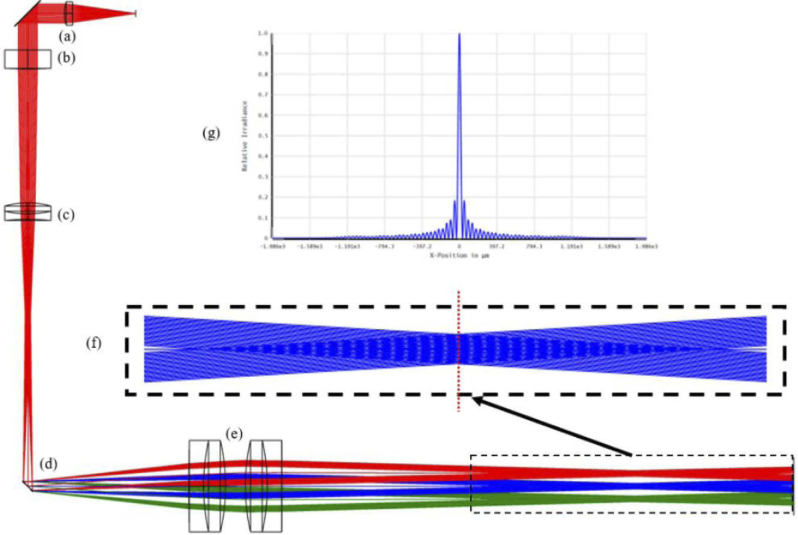
Figure 2 shows the ray-tracing simulation of the sample arm designed for the OCT system, using the Zemax OpticStudio software. The collimated output of the fiber optics (a), with a beam diameter of 3.4 mm, was incident to an axicon lens with an apex angle of two degrees (b); it was followed by an achromatic lens (c). Galvanometer scanner (d) directed the ring-shaped beam beyond the axicon to the achromatic lens (e). Focusing this ring-shaped beam also generates self-interfering beams, which result in a second BLB with an extended DOF. Figure 2(f) illustrates the zoomed generated BLB behind the achromatic lens pairs. Figure 2(g) is corresponding to the cross-section of the computed point spread function using Fast Fourier Transform (FFT) at the center of BLB. The corresponding calculated DOF of the simulated BLB using Zemax OpticStudio software is 25.7 mm.
Fig. 2.
Ray-tracing simulation calculated using Zemax OpticStudio software for the sample arm of the OCT system. (a) the collimator, (b) axicon lens with apex angle of two degrees, (c) achromatic doublet lens (f = 75 mm), (d) two-dimensional galvanometer scanner, (e) achromatic lens pairs (f = 100 mm). (f) Zoomed illustration of the generated BLB, (g) cross-section of the computed PSF at the focal plane of the achromatic lens pair, where dashed red line is shown in (f).
2.3.2. Integrated setup
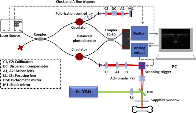
Figure 3 gives an overview of the integrated system. The OCT system consisted of a fiber-based Michelson interferometer, a programmable akinetic swept-source laser (Insight Photonic Solution, Inc., Lafayette, Co, USA), and a balanced photodetector (PDB48xC-AC). In the sample arm of the OCT system, the collimated beam (after C1) was incident on an axicon lens (A1) with an apex angle of two degrees. An achromatic lens with a focal length of 75 mm (L1) was placed after the conical lens to focus the ring-shaped beam onto the Galvano scanner’s relatively small size (3 mm). A two-dimensional galvanometer scanner directed the ring-shaped beam to an achromatic lens pair (1:1 with 100 mm effective focal length). Focusing the ring-shaped beam resulted in self-interfering beams, which generated the second BLB with an extended DOF.
Fig. 3.
Schematic of the integrated long-range and extended DOF OCT system for laser ablation. An Er:YAG laser is integrated into the sample arm of the OCT system using a dichroic filter.
In the reference arm, a dispersion compensator (DC) and an axicon lens (A2) with an apex angle of two degrees were placed after the collimator lens (C2) to compensate for the dispersion mismatch between the sample arm and the reference arm. The laser source in the OCT system operated at a central wavelength of 1310 nm, a spectral bandwidth of 61.5 nm, and an A-scan line rate of 111.61 kHz. The imaging range of the OCT system is equal to 26.2 mm in the air. In this experiment, we set the OCT system parameters in such a way as to capture B-scans, including 400 A-scans, which could provide a field of view of 4.3 × 4.3 mm2. The captured raw data was processed using DC subtraction, averaging filter, and fixed-term noise subtraction. The Er:YAG laser (LITETOUCH by Syneron) was integrated with the OCT system, using a custom-made dichromatic filter that transmits the OCT’s laser beam and reflects the beam of the Er:YAG laser. A 75 mm calcium fluoride (CaF2) lens was utilized to focus the ablation laser onto the surface of the bone. A protective window was also placed after the dichroic filter to protect the optical elements from the debris as well as water droplets. As debris and/or water accumulate on the protective window, it could be exposed to high laser energy due to the absorption by debris and/or water. Thus, a window (e.g., sapphire, magnesium fluoride) with a high damage threshold is needed. In this experiment, we used a sapphire window with 2 mm thickness. The bone was placed within the focal region of both the Er:YAG and OCT lasers.
2.4. Irrigation system
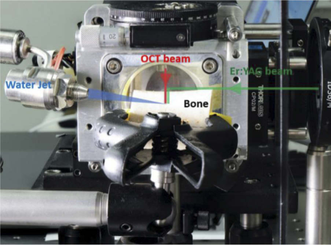
A water jet was directed to the ablation spot to improve ablation efficiency. Using a water-based irrigation system prevents the carbonization of the bone during laser ablation and rehydrates the surface of the bone. A specially designed nozzle from Synova Laser MicroJet Technology was used in the experiments which can produce laminar water flow within a 50 µm diameter with 10-800 bar pressure [58]. Figure 4 demonstrates a photograph of the experimental setup. Er:YAG and OCT lasers were aligned to be in a coaxial path using a dichroic filter; in addition, a water jet (at 30 bar pressure) is aimed at the ablation spot to prevent carbonization. Since water has one of its highest absorption peaks around 3 µm, which overlaps with the operation wavelength of the Er:YAG laser, water accumulation on the surface of the sample reduces the efficiency of ablation. Therefore, we also used a continuous air pressure nozzle directed to the ablation spot to extract the accumulated water and debris from the laser-induced cut.
Fig. 4.
Photograph of the setup used for ablation of femur bone sample. The OCT and Er:YAG lasers are combined using a dichroic filter. To avoid carbonization and enhance the efficiency of ablation, a water jet and a pressurized air nozzle are aimed at the ablation crater, respectively.
2.5. Comparison of performance of the BLB and Gaussian beam in the presence of imaging artifacts
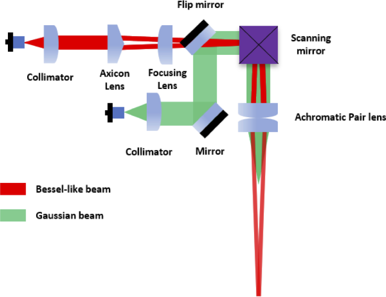
Figure 5 demonstrates the schematic of the sample arm of the OCT system to compare the performance of BLB and Gaussian beam. In Fig. 5, red and green beam trajectories correspond to the BLB and Gaussian beam, respectively. To integrate the Gaussian beam, we utilized the same optical fiber and collimator which have been used in the BLB path (Fig. 4), and an additional flip mirror. We switched between these two arms by using a flip mirror. In addition, during the experiments, the corresponding sample arm was connected to the interferometer. To compare the performance of BLB and Gaussian beam, we created three different conditions of the protective window (sapphire window in Fig. 3): clean, covered with debris, and covered with water droplets. The 2D intensity profile of each beam after passing the protective window was recorded within the imaging range of the OCT system using a camera (BFLY-U3-23S6M-C, FLIR).
Fig. 5.
Schematic of the sample arm of the OCT system for comparing the performance of BLB and Gaussian beam. In this experimental setup, switching between Gaussian beam and BLB is possible using the flip mirror.
One inherent drawback of the Bessel beam is the signal-to-noise ratio (SNR) penalty due to the small fraction of power in the central lobe of the Bessel beam [59]. However, comparing the SNR of the BB and Gaussian beam using the conventional method (placing a reflector instead of the sample) is not feasible for BLB mainly because the back-coupled signal in the BB case will include the contributions from the sidelobes. Therefore, this comparison was made by comparing the sensitivity of these beams. Illumination efficiency and collection efficiency for both sample arms were measured at different conditions of the protective window (clean, covered with debris, and covered with water droplets) by using the method described by Lee. et al. [60]. The incident beam power of 8 mW is measured by a power meter. For the BLB case, the collection efficiency was measured using a conventual lens (LSM05, Thorlabs). The on-axis sensitivity of BLB in different conditions of the protective window was determined by subtracting the illumination efficiency and collection efficiency from the corresponding peak sensitivity of the Gaussian beam.
3. Results
3.1. Extending depth-of-focus of OCT using Bessel-like beams
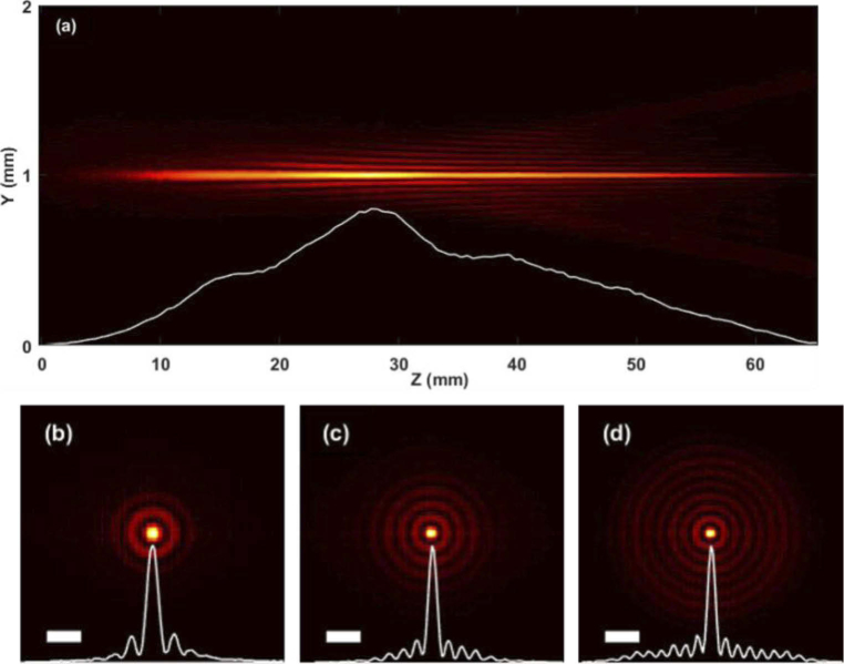
Figure 6(a) illustrates the cross-sectional intensity profile of the BLB in the sample arm of the OCT system. The evolution of the BLB was recorded by a camera, with a step size of 0.5 mm in the propagation direction (z-direction). The white curve [Fig. 6(a)] indicates the corresponding variation of intensity of the central peak as a function of the propagation distance. The DOF of the BLB was measure as 28.7 mm (full width at half maximum (FWHM)), which exceed the imaging range of 26.2 mm in the experiment. Figures 6(b)–6(d) demonstrate the 2D intensity profiles of the BLB at z = 20 mm, z = 40 mm, and z = 60 mm with corresponding point spread function of 38.6 µm, 29 µm, and 26 µm, respectively.
Fig. 6.
(a) Measured cross-sectional intensity profile of the experimentally-generated BLB, and propagation is from left to right. The variation of the intensity profile of the central peak of the BLB over 65 mm propagation distance, where FWHM was 28.7 mm. Cross-sectional intensity image of the BLB at (b) z = 20 mm, (c) z = 40 mm, and (d) z = 60 mm. The point spread function of (b)-(c) is 38.6 µm, 29 µm, and 26 µm, respectively. The scale bar is 100 µm.
3.2. Imaging artifacts
3.2.1. Debris
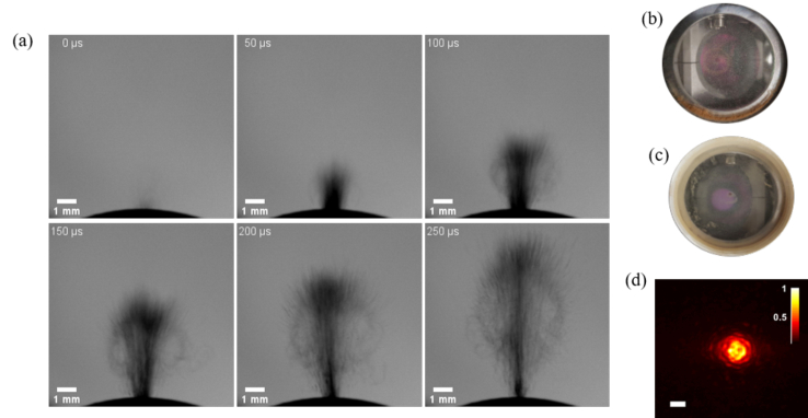
When ablative laser pulses are directed onto biological tissue, ablated particles are emitted above the tissue surface. Figure 7(a) demonstrates the generation debris with time-steps of 50 µsec after shooting an Er:YAG laser pulse to the surface of the bone. Figures 7(b) and 7(c) illustrate the window covered with debris. Figure 7(d) depicts the OCT beam with a Gaussian intensity distribution, which was obtained after the protective window [Fig. 7(d)].
Fig. 7.
(a) Debris formation over time, from the onset of an Er:YAG laser pulse onto hard tissue. These images are captured using shadowgraphy method. (b)-(c) Debris accumulated on the sapphire. (d) Intensity profile of the Gaussian beam after passing through the windows covered with debris (scalebar = 200 µm).
3.2.2. Water droplets
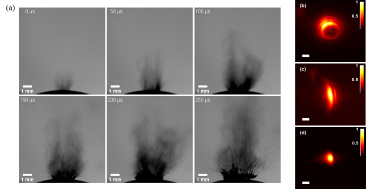
Laser surgery using an Er:YAG laser system is usually integrated with a water spray. Figure 8(a) corresponds to the explosion of water accumulated inside the incision (time-steps are 50 µsec). Figures 8(b)–8(d) illustrate a Gaussian beam interaction with water droplets on the protective window. These images were acquired at different axial and lateral positions to demonstrate different artifacts induced by water droplets on the protective window.
Fig. 8.
(a) The explosion of water accumulated inside the cut after shooting Er:YAG laser pulse. These images are captured using the shadowgraphy method (time-steps are 50 µsec). (b)-(d) Intensity profile of the Gaussian beam after passing through the protective window covered with water droplets. The scale bar is 200 µm.
3.3. Interaction of the BLB and Gaussian beam with debris and water droplets
Debris and water droplets generated during laser osteotomy pose significant challenges to the visual feedback system, mainly due to their interaction with laser light. These interactions may reduce the quality of the images collected by the OCT system. Note that, since the accumulation of water droplets and debris were random during laser ablation of the bone, it was not feasible to compare the performance of the BLB OCT and the Gaussian beam OCT in real-time monitoring of laser osteotomy. Therefore, these comparisons are made by using a protective window that was deliberately kept clean, covered with debris, and covered with water droplets.
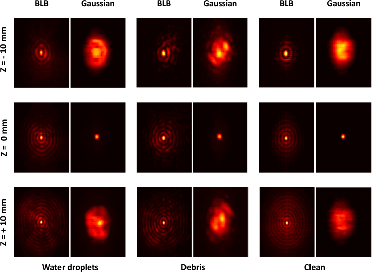
To investigate the influence of debris and water droplets on the quality of the imaging system, we captured the 2D intensity profile of the BLB and Gaussian beam after the protective window. Since water droplets on the sapphire window were unstable due to movement or evaporation, we used a window with a hydrophobic coating to capture the intensity profile of the beam. Figure 9 illustrates the intensity profile variation with respect to distance from the focal plane for the three cases.
Fig. 9.
Intensity profile of Bessel-like beam and Gaussian beam after passing through the protective window under three conditions: clean, covered with debris, and covered with water droplets. Each column represents one of these situations, starting from Z = -10 mm, to Z = 10 mm from the focus point. The size of the images is 1 mm × 1 mm.
The three columns in Fig. 9 present the intensity profile of the BLB and Gaussian beam when it passed through a window covered with water droplets, covered with debris, and the clean window, respectively. Each raw represents the relative distance to the focal plane of the Gaussian beam and BLB. The interaction of the Gaussian beam and BLB with debris and water droplets on the surface of the protective window results in a distorted 2D intensity profile. However, BLB demonstrated superior performance in comparison to Gaussian beam due to the so-called self-healing properties.
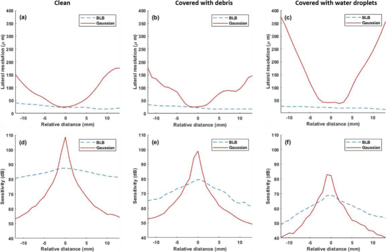
To investigate the performance of the BLB and the Gaussian beam for monitoring the depth of ablation in laser osteotomy, lateral resolution and sensitivity of each beam have been compared. Figure 10 demonstrates the comparison of lateral resolution and sensitivity of the BLB and the Gaussian beam in different conditions of the protective window. First raw [Figs. 10(a)–10(c)] illustrates the measured lateral resolution for each experiment. In Fig. 10(a), the lateral resolution of 23 µm and 25 µm were measured for the BLB and Gaussian beam, respectively. Figures 10(b)–10(d) demonstrate the effect of the imaging artifacts on the lateral resolution of the Gaussian beam; however, the BLB showed approximately an invariant lateral resolution (less than 11 µm within 2.6 cm) in different condition of the sapphire window. The second raw in Fig. 10 demonstrates the measured sensitivity of the BLB and the Gaussian beam. For the Gaussian beam, on-axis peak sensitivities of 108 dB, 98 dB, and 82 dB were measured for a clean, covered with debris, and covered with water droplets, respectively. The sensitivity of the BLB was determined by subtracting the illumination efficiency and collection efficiency from peak sensitivity in each case. The SNR penalty of using BLB is visible in Figs. 10(d)–10(f). The higher sensitivity region of the Gaussian beam is localized over its DOF, while BLB shows a considerably higher sensitivity along with the imaging range.
Fig. 10.
Comparison of lateral resolution (a-c) and sensitivity (d-f) for Gaussian and BLB cases at different conditions of the sapphire window: clean [(a) and (d)], covered with debris [(b) and (e)], and covered with water droplets [(c) and (f)]. Gaussian beam and BLB are delineated with continuous red and dashed blue lines, respectively.
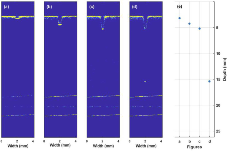
Furthermore, the power ratio (ratio between the central peak and sidelobe) of the normalized intensity profile of BLB at the focus were measured as 0.21, 0.28, 0.37 in a clean protective window, covered with debris, and covered with water droplets, respectively. As it is visible in Fig. 11, the sidelobes of the BLB do not cause any significant artifacts during real-time monitoring of the laser osteotomy.
Fig. 11.
Selected images during a laser ablation process of bone collected using the long-range and extended DOF OCT system. (a)-(d) real-time depth monitoring of laser ablation of the femoral bone. (d) In this image, the ablative laser cut through the cortical line of the femur bone and reached the surface of the cortical bone in the medullary cavity. (e) The measured depth of cuts within the imaging range of the OCT system.
3.4. Real-time monitoring of laser ablation of bone
For this experiment, we placed a pig femur at the focal plane of the integrated BLB OCT and laser ablation system. The ablation laser’s output energy and repetition frequency were 220 mJ and 1 Hz, respectively. To monitor the ablation procedure of the femur bone, we ran the OCT system continuously, starting before administering the first laser pulse to the end of the ablation procedure. Figures 11(a)–11(d) represent selected images captured within the imaging range of the OCT. Figure 11(d) shows that the ablative laser passed through the cortical line of the femur bone, reaching the surface of the cortical bone in the medullary cavity. Figure 11(e) shows the deepest point of the ablated cut with the OCT images presented. The depth of the incisions in Figs. 11(a)–11(d) is 0.5 mm, 1.57 mm, 2.53 mm, and 12.72 mm, respectively. The cutting width is measured as ∼ 0.56 mm. The time difference between Figs. 11(a)–11(d) is 51 seconds, which corresponds to 51 pulses of the Er:YAG laser. The thickness of the cortical line of the femur bone to the medullary cavity was 2.54 mm, and the diameter of the medullary cavity was 10.1 mm, which was measured with a caliper.
4. Discussion and conclusion
This study demonstrated the feasibility of using a long-range optical coherence tomography system to provide visual feedback during laser osteotomy. Laser osteotomy often generates image artifacts (especially in deep ablation) that hinder the OCT system; thus, we investigated the potential of a Bessel-like beam (BLB-OCT) to extend the DOF of the long-range OCT system and to improve the quality of acquired images by reducing the effect of such artifacts.
The proposed method offers some unique advantages over existing designs that employ a Gaussian beam in the OCT system to monitor the ablation procedure. A long-range imaging system can be used when deep laser-induced cuts (in order of cm) are required. Likewise, the most effective approach to reducing image artifacts is to place the sample further away from the protective window. Although this configuration is not practical for minimally invasive surgical procedures, a free-space integrated setup would benefit from the reduction of debris and water droplets that reach the protective window. Such a setup would require an optimized ablation laser with an extended DOF to perform a deep ablation, which is beyond the scope of this paper. In our configuration, just a fraction of the debris reaches the protective window. The debris cloud scatters laser light close to the sample's surface [61]. As can be seen from Fig. 10, the BLB-OCT shows a superior lateral resolution and sensitivity in comparison to the Gaussian beam within the imaging range, especially in the presence of imaging artifacts (accumulated debris and water droplets) on the protective window. However, it worth mentioning that the protective window needs to be cleaned in a long-term ablation. An additional feedback system that controls the irrigation system would enhance the quality of the OCT images further. Another approach would be the use of the OCT system as a feedback system for the irrigation system. Lastly, the proposed method has the absence of a depth control system that can stop the ablative laser after reaching the desired depth of the incision.
Using a novel long-range extended DOF BLB-OCT system to provide visual feedback during laser ablation, we demonstrated real-time monitoring of laser osteotomy. Using the BLB-OCT, we demonstrated how self-healing property improves the quality of the OCT images in the case of debris and water droplet accumulation. We believe that the proposed BLB-OCT system has the potential to be used in smart laser osteotomy involving deep incisions. Controlling the irrigation system, miniaturizing this system, and providing depth control to be used in a minimally invasive device are of future interest.
Funding
Werner Siemens Foundation10.13039/100016964 through the Minimally Invasive Robot-Assisted Computer-guided LaserosteotomE (MIRACLE) project.
Disclosures
The authors declare no conflicts of interest.
References
- 1.Baek K. W., Deibel W., Marinov D., Griessen M., Dard M., Bruno A., Zeilhofer H. F., Cattin P., Juergens P., “A comparative investigation of bone surface after cutting with mechanical tools and Er:YAG laser,” Lasers Surg. Med. 47(5), 426–432 (2015). 10.1002/lsm.22352 [DOI] [PubMed] [Google Scholar]
- 2.Zhang Y., Wang C., Zhou S., Jiang W., Liu Z., Xu L., “A comparison review on orthopedic surgery using piezosurgery and conventional tools,” Procedia Cirp 65, 99–104 (2017). 10.1016/j.procir.2017.04.024 [DOI] [Google Scholar]
- 3.Eyrich G. K., “Laser-osteotomy induced changes in bone,” Medical Laser Application 20(1), 25–36 (2005). 10.1016/j.mla.2005.02.003 [DOI] [Google Scholar]
- 4.Augello M., Baetscher C., Segesser M., Zeilhofer H.-F., Cattin P., Juergens P., “Performing partial mandibular resection, fibula free flap reconstruction and midfacial osteotomies with a cold ablation and robot-guided Er:YAG laser osteotome (CARLO®)–A study on applicability and effectiveness in human cadavers,” Journal of Cranio-Maxillofacial Surgery 46(10), 1850–1855 (2018). 10.1016/j.jcms.2018.08.001 [DOI] [PubMed] [Google Scholar]
- 5.Ivanenko M., Werner M., Afilal S., Klasing M., Hering P., “Ablation of hard bone tissue with pulsed CO2 lasers,” Medical Laser Application 20(1), 13–23 (2005). 10.1016/j.mla.2005.02.007 [DOI] [Google Scholar]
- 6.Lee Y.-M., Tu R., Chiang A., Huang Y.-C., “Average-power mediated ultrafast laser osteotomy using a mode-locked Nd: YVO 4 laser oscillator,” J. Biomed. Opt. 12(6), 060505 (2007). 10.1117/1.2821149 [DOI] [PubMed] [Google Scholar]
- 7.Mauceri R., Panzarella V., Maniscalco L., Bedogni A., Licata M. E., Albanese A., Toia F., Cumbo E. M. G., Mazzola G., Di Fede O., “Conservative surgical treatment of bisphosphonate-related osteonecrosis of the jaw with Er, Cr: YSGG laser and platelet-rich plasma: a longitudinal study,” BioMed Res. Int. 2018, 1–10 (2018). 10.1155/2018/3982540 [DOI] [PMC free article] [PubMed] [Google Scholar]
- 8.Panduric D. G., Juric I. B., Music S., Molčanov K., Sušic M., Anic I., “Morphological and ultrastructural comparative analysis of bone tissue after Er:YAG laser and surgical drill osteotomy,” Photomed. Laser Surg. 32(7), 401–408 (2014). 10.1089/pho.2014.3711 [DOI] [PubMed] [Google Scholar]
- 9.Stübinger S., “Advances in bone surgery: the Er:YAG laser in oral surgery and implant dentistry,” Clin., Cosmet. Invest. Dent. 2, 47–62 (2010). 10.2147/CCIDE.S8352 [DOI] [PMC free article] [PubMed] [Google Scholar]
- 10.Bay E., Deán-Ben X. L., Pang G. A., Douplik A., Razansky D., “Real-time monitoring of incision profile during laser surgery using shock wave detection,” J. Biophotonics 8(1-2), 102–111 (2015). 10.1002/jbio.201300151 [DOI] [PubMed] [Google Scholar]
- 11.Boppart S. A., Herrmann J., Pitris C., Stamper D. L., Brezinski M. E., Fujimoto J. G., “High-resolution optical coherence tomography-guided laser ablation of surgical tissue,” J. Surg. Res. 82(2), 275–284 (1999). 10.1006/jsre.1998.5555 [DOI] [PubMed] [Google Scholar]
- 12.Hamidi A., Bayhaqi Y. A., Canbaz F., Navarini A., Cattin P. C., Zam A., “Imaging photothermal-induced expansion of bone during laser osteotomy by phase-sensitive OCT: preliminary results,” in Biomedical Spectroscopy, Microscopy, and Imaging, (International Society for Optics and Photonics, 2020), 113590 K. [Google Scholar]
- 13.Kenhagho H. N., Sugiarto I., Guzman R., Cattin P., Zam A., “Contact-free Crater Depth Monitoring Using Measured Acoustic Shock Waves for Smart Laser Surgery Applications: Preliminary Result,” in 2019 International Conference on Radar, Antenna, Microwave, Electronics, and Telecommunications (ICRAMET), (IEEE, 2019), 118–121. [Google Scholar]
- 14.Landa F. J. O., Deán-Ben X. L., de Espinosa F. M., Razansky D., “Noncontact monitoring of incision depth in laser surgery with air-coupled ultrasound transducers,” Opt. Lett. 41(12), 2704–2707 (2016). 10.1364/OL.41.002704 [DOI] [PubMed] [Google Scholar]
- 15.Mezzapesa F. P., Columbo L., Brambilla M., Dabbicco M., Ancona A., Sibillano T., De Lucia F., Lugarà P. M., Scamarcio G., “Simultaneous measurement of multiple target displacements by self-mixing interferometry in a single laser diode,” Opt. Express 19(17), 16160–16173 (2011). 10.1364/OE.19.016160 [DOI] [PubMed] [Google Scholar]
- 16.Webster P. J., Wright L. G., Mortimer K. D., Leung B. Y., Yu J. X., Fraser J. M., “Automatic real-time guidance of laser machining with inline coherent imaging,” J. Laser Appl. 23(2), 022001 (2011). 10.2351/1.3567955 [DOI] [Google Scholar]
- 17.Zakharov A., Volkov M., Gurov I., Temnov V., Sokolovski-Tinten K., Von Der Linde D., “Interferometric diagnostics of ablation craters formed by femtosecond laser pulses,” J. Opt. Technol. 69(7), 478 (2002). 10.1364/JOT.69.000478 [DOI] [Google Scholar]
- 18.Juhasz T., Hu X. H., Turi L., Bor Z., “Dynamics of shock waves and cavitation bubbles generated by picosecond laser pulses in corneal tissue and water,” Lasers Surg. Med. 15(1), 91–98 (1994). 10.1002/lsm.1900150112 [DOI] [PubMed] [Google Scholar]
- 19.Walsh J., Deutsch T., “Measurement of Er:YAG laser ablation plume dynamics,” Appl. Phys. B 52(3), 217–224 (1991). 10.1007/BF00750954 [DOI] [Google Scholar]
- 20.Drexler W., Fujimoto J. G., Optical Coherence Tomography: Technology and Applications (Springer Science & Business Media, 2008). [Google Scholar]
- 21.Fujimoto J. G., Drexler W., “Introduction to OCT,” in Optical Coherence Tomography (Springer, 2015), pp. 3–64. [Google Scholar]
- 22.Izatt J. A., Choma M. A., “Theory of optical coherence tomography,” in Optical Coherence Tomography (Springer, 2008), pp. 47–72. [Google Scholar]
- 23.Bao W., Ding Z., Qiu J., Shen Y., Li P., Chen Z., “Quasi-needle-like focus synthesized by optical coherence tomography,” Opt. Lett. 42(7), 1385–1388 (2017). 10.1364/OL.42.001385 [DOI] [PubMed] [Google Scholar]
- 24.Yu L., Rao B., Zhang J., Su J., Wang Q., Guo S., Chen Z., “Improved lateral resolution in optical coherence tomography by digital focusing using two-dimensional numerical diffraction method,” Opt. Express 15(12), 7634–7641 (2007). 10.1364/OE.15.007634 [DOI] [PubMed] [Google Scholar]
- 25.Dubois A., Levecq O., Azimani H., Siret D., Barut A., Suppa M., Del Marmol V., Malvehy J., Cinotti E., Rubegni P., “Line-field confocal optical coherence tomography for high-resolution noninvasive imaging of skin tumors,” J. Biomed. Opt. 23(10), 1 (2018). 10.1117/1.JBO.23.10.106007 [DOI] [PubMed] [Google Scholar]
- 26.Adie S. G., Shemonski N. D., Ralston T. S., Carney P. S., Boppart S. A., “Interferometric synthetic aperture microscopy (ISAM),” oct, 965 (2015).
- 27.Bo E., Ge X., Wang L., Wu X., Luo Y., Chen S., Chen S., Liang H., Ni G., Yu X., “Multiple aperture synthetic optical coherence tomography for biological tissue imaging,” Opt. Express 26(2), 772–780 (2018). 10.1364/OE.26.000772 [DOI] [PubMed] [Google Scholar]
- 28.Bo E., Luo Y., Chen S., Liu X., Wang N., Ge X., Wang X., Chen S., Chen S., Li J., “Depth-of-focus extension in optical coherence tomography via multiple aperture synthesis,” Optica 4(7), 701–706 (2017). 10.1364/OPTICA.4.000701 [DOI] [Google Scholar]
- 29.Curatolo A., Munro P. R., Lorenser D., Sreekumar P., Singe C. C., Kennedy B. F., Sampson D. D., “Quantifying the influence of Bessel beams on image quality in optical coherence tomography,” Sci. Rep. 6(1), 23483 (2016). 10.1038/srep23483 [DOI] [PMC free article] [PubMed] [Google Scholar]
- 30.Hermann B., Fernández E., Unterhuber A., Sattmann H., Fercher A., Drexler W., Prieto P., Artal P., “Adaptive-optics ultrahigh-resolution optical coherence tomography,” Opt. Lett. 29(18), 2142–2144 (2004). 10.1364/OL.29.002142 [DOI] [PubMed] [Google Scholar]
- 31.Liu L., Diaz F., Wang L., Loiseaux B., Huignard J.-P., Sheppard C., Chen N., “Superresolution along extended depth of focus with binary-phase filters for the Gaussian beam,” J. Opt. Soc. Am. A 25(8), 2095–2101 (2008). 10.1364/JOSAA.25.002095 [DOI] [PubMed] [Google Scholar]
- 32.Ralston T. S., Adie S. G., Marks D. L., Boppart S. A., Carney P. S., “Cross-validation of interferometric synthetic aperture microscopy and optical coherence tomography,” Opt. Lett. 35(10), 1683–1685 (2010). 10.1364/OL.35.001683 [DOI] [PMC free article] [PubMed] [Google Scholar]
- 33.Sasaki K., Kurokawa K., Makita S., Yasuno Y., “Extended depth of focus adaptive optics spectral domain optical coherence tomography,” Biomed. Opt. Express 3(10), 2353–2370 (2012). 10.1364/BOE.3.002353 [DOI] [PMC free article] [PubMed] [Google Scholar]
- 34.Simon D. S., “Bessel beams, self-healing, and diffraction-free propagation,” in A Guided Tour of Light Beams: From Lasers to Optical Knots (IOP Concise Physics, 2016), pp. 1–15. 10.1088/978-1-6817-4437-7ch5 [DOI] [Google Scholar]
- 35.Fan Y., Zhang B., Chang W., Zhang X., Liao H., “A novel integration of spectral-domain optical-coherence-tomography and laser-ablation system for precision treatment,” International journal of computer assisted radiology and surgery 13(3), 411–423 (2018). 10.1007/s11548-017-1664-8 [DOI] [PubMed] [Google Scholar]
- 36.Oh W.-Y., Yun S., Vakoc B., Tearney G., Bouma B., “Ultrahigh-speed optical frequency domain imaging and application to laser ablation monitoring,” Appl. Phys. Lett. 88(10), 103902 (2006). 10.1063/1.2179125 [DOI] [Google Scholar]
- 37.Webster P. J., Muller M. S., Fraser J. M., “High speed in situ depth profiling of ultrafast micromachining,” Opt. Express 15(23), 14967–14972 (2007). 10.1364/OE.15.014967 [DOI] [PubMed] [Google Scholar]
- 38.Beaudette K., Baac H. W., Madore W.-J., Villiger M., Godbout N., Bouma B. E., Boudoux C., “Laser tissue coagulation and concurrent optical coherence tomography through a double-clad fiber coupler,” Biomed. Opt. Express 6(4), 1293–1303 (2015). 10.1364/BOE.6.001293 [DOI] [PMC free article] [PubMed] [Google Scholar]
- 39.Beaudette K., Lo W., Villiger M., Shishkov M., Godbout N., Bouma B. E., Boudoux C., “Towards in vivo laser coagulation and concurrent optical coherence tomography through double-clad fiber devices,” in Multimodal Biomedical Imaging XI (International Society for Optics and Photonics, 2016), 97010B. [Google Scholar]
- 40.Liang S., Sun C., Saidi A., Jing J., Liu G., Li J., Zhang J., Chen Z., Narula J., “Intravascular atherosclerotic imaging with combined fluorescence and optical coherence tomography probe based on a double-clad fiber combiner,” J. Biomed. Opt. 17, 070501 (2012). 10.1117/1.JBO.17.7.070501 [DOI] [PMC free article] [PubMed] [Google Scholar]
- 41.Pahlevaninezhad H., Lee A. M., Shaipanich T., Raizada R., Cahill L., Hohert G., Yang V. X., Lam S., MacAulay C., Lane P., “A high-efficiency fiber-based imaging system for co-registered autofluorescence and optical coherence tomography,” Biomed. Opt. Express 5(9), 2978–2987 (2014). 10.1364/BOE.5.002978 [DOI] [PMC free article] [PubMed] [Google Scholar]
- 42.Bonesi M., Minneman M., Ensher J., Zabihian B., Sattmann H., Boschert P., Hoover E., Leitgeb R., Crawford M., Drexler W., “Akinetic all-semiconductor programmable swept-source at 1550 nm and 1310 nm with centimeters coherence length,” Opt. Express 22(3), 2632–2655 (2014). 10.1364/OE.22.002632 [DOI] [PubMed] [Google Scholar]
- 43.Song S., Xu J., Wang R. K., “Long-range and wide field of view optical coherence tomography for in vivo 3D imaging of large volume object based on akinetic programmable swept source,” Biomed. Opt. Express 7(11), 4734–4748 (2016). 10.1364/BOE.7.004734 [DOI] [PMC free article] [PubMed] [Google Scholar]
- 44.Jowett N., Wöllmer W., Reimer R., Zustin J., Schumacher U., Wiseman P. W., Mlynarek A. M., Böttcher A., Dalchow C. V., Lörincz B. B., “Bone ablation without thermal or acoustic mechanical injury via a novel picosecond infrared laser (PIRL),” Otolaryngol.--Head Neck Surg. 150(3), 385–393 (2014). 10.1177/0194599813517213 [DOI] [PubMed] [Google Scholar]
- 45.Bernal L. M. B., Schmidt I. T., Vulin N., Widmer J., Snedeker J. G., Cattin P. C., Zam A., Rauter G., “Optimizing controlled laser cutting of hard tissue (bone),” at-Automatisierungstechnik 66(12), 1072–1082 (2018). 10.1515/auto-2018-0072 [DOI] [Google Scholar]
- 46.Tuchin V., “Tissue optics and photonics: Light-tissue interaction II,” J. Biomed. Photonics Eng. 2(3), 030201 (2016). 10.18287/JBPE16.02.030201 [DOI] [Google Scholar]
- 47.Eriksson R., Albrektsson T., Magnusson B., “Assessment of bone viability after heat trauma: a histological, histochemical and vital microscopic study in the rabbit,” Scand. J. Plast. Reconstr. Surg. 18(3), 261–268 (1984). 10.3109/02844318409052849 [DOI] [PubMed] [Google Scholar]
- 48.Visuri S. R., Walsh J. T., Jr, Wigdor H. A., “Erbium laser ablation of dental hard tissue: effect of water cooling,” Lasers in Surgery and Medicine 18, 294–300 (1996). [DOI] [PubMed] [Google Scholar]
- 49.Dubey A. K., Yadava V., “Laser beam machining—a review,” International Journal of Machine Tools and Manufacture 48(6), 609–628 (2008). 10.1016/j.ijmachtools.2007.10.017 [DOI] [Google Scholar]
- 50.Rachmanis N., McGuinness G. B., McGeough J. A., “Characterisation of debris from laser and mechanical cutting of bone,” Proc. Inst. Mech. Eng., Part H 228(7), 735–739 (2014). 10.1177/0954411914541089 [DOI] [PubMed] [Google Scholar]
- 51.Nahen K., Vogel A., “Plume dynamics and shielding by the ablation plume during Er:YAG laser ablation,” J. Biomed. Opt. 7(2), 165–179 (2002). 10.1117/1.1463047 [DOI] [PubMed] [Google Scholar]
- 52.Arlt J., Garcés-Chávez V., Sibbett W., Dholakia K., “Optical micromanipulation using a Bessel light beam,” Opt. Commun. 197(4-6), 239–245 (2001). 10.1016/S0030-4018(01)01479-1 [DOI] [Google Scholar]
- 53.Apitz I., Vogel A., “Material ejection in nanosecond Er:YAG laser ablation of water, liver, and skin,” Appl. Phys. A 81(2), 329–338 (2005). 10.1007/s00339-005-3213-5 [DOI] [Google Scholar]
- 54.Ding Z., Ren H., Zhao Y., Nelson J. S., Chen Z., “High-resolution optical coherence tomography over a large depth range with an axicon lens,” Opt. Lett. 27(4), 243–245 (2002). 10.1364/OL.27.000243 [DOI] [PubMed] [Google Scholar]
- 55.Leitgeb R., Villiger M., Bachmann A., Steinmann L., Lasser T., “Extended focus depth for Fourier domain optical coherence microscopy,” Opt. Lett. 31(16), 2450–2452 (2006). 10.1364/OL.31.002450 [DOI] [PubMed] [Google Scholar]
- 56.Ismail Y., Khilo N., Belyi V., Forbes A., “Shape invariant higher-order Bessel-like beams carrying orbital angular momentum,” J. Opt. 14(8), 085703 (2012). 10.1088/2040-8978/14/8/085703 [DOI] [Google Scholar]
- 57.Belyi V., Forbes A., Kazak N., Khilo N., Ropot P., “Bessel–like beams with z–dependent cone angles,” Opt. Express 18(3), 1966–1973 (2010). 10.1364/OE.18.001966 [DOI] [PubMed] [Google Scholar]
- 58.Bernal L. M. B., Canbaz F., Droneau A., Friederich N. F., Cattin P. C., Zam A., “Optimizing deep bone ablation by means of a microsecond Er:YAG laser and a novel water microjet irrigation system,” Biomed. Opt. Express 11(12), 7253–7272 (2020). 10.1364/BOE.408914 [DOI] [PMC free article] [PubMed] [Google Scholar]
- 59.Lorenser D., Singe C. C., Curatolo A., Sampson D. D., “Energy-efficient low-Fresnel-number Bessel beams and their application in optical coherence tomography,” Opt. Lett. 39(3), 548–551 (2014). 10.1364/OL.39.000548 [DOI] [PubMed] [Google Scholar]
- 60.Lee K.-S., Rolland J. P., “Bessel beam spectral-domain high-resolution optical coherence tomography with micro-optic axicon providing extended focusing range,” Opt. Lett. 33(15), 1696–1698 (2008). 10.1364/OL.33.001696 [DOI] [PubMed] [Google Scholar]
- 61.Gutknecht N., Lukac M., Marincek M., Perhavec T., Kazic M., “A novel quantum square pulse (QSP) mode erbium dental laser,” J LAHA 1, 15–21 (2011). [Google Scholar]


