Abstract
We present a significant step toward ultrahigh-resolution, motion-insensitive characterization of vascular dynamics. Optical coherence tomography angiography (OCTA) is an invaluable diagnostic technology for non-invasive, label-free vascular imaging in vivo. However, since it relies on detecting moving cells from consecutive scans, high-resolution OCTA is susceptible to tissue motion, which imposes challenges in resolving and quantifying small vessels. We developed a novel OCTA technique named ultrahigh-resolution factor angiography (URFA) by modeling repeated scans as generative latent variables, with a common variance representing shared features and a unique variance representing motion. By iteratively maximizing the combined log-likelihood probability of these variances, the unique variance is largely separated. Meanwhile, features in the common variance are decoupled, in which vessels with dynamic flow are extracted from tissue structure by integrating high-order factors. Combined with Gabor-domain optical coherence microscopy, URFA successfully extracted high-resolution cutaneous vasculature despite severe involuntary tissue motion and scanner oscillation, significantly improving the visualization and characterization of micro-capillaries in vivo. Compared with the conventional approach, URFA reduces motion artifacts by nearly 50% on average, evaluated on local differences.
1. Introduction
Three-dimensional (3D) imaging of biological tissue in vivo with high resolution is essential for diagnosing and treating pathological conditions. Various optical imaging techniques have been developed to achieve this purpose, among which optical coherence tomography (OCT) has proven its clinical significance for non-invasive diagnoses in ophthalmology [1], dermatology [2], neurology [3], et al.
In addition to the OCT-imaged anatomic structure, the blood vessels in the micro-circulatory tissue bed support crucial tissue metabolism functions by exchanging nutrients and oxygen with proximal cells. The functional extension of OCT to visualize tissue perfusion together with the co-registered structure aids in monitoring the disease progression and accordingly adjusting the medical interventions. Relying upon label-free endogenous flow of blood cells, one promising way of imaging the perfusion is done with repeated scans of the tissue structure and high-pass filtering the flow component with the methods of speckle differentiation [4], speckle decorrelation [5–7], or analysis of Doppler effect [8,9], generally known as OCT angiography (OCTA). These processing methods share the same underlying concept, i.e., extracting the large variations in repeated scans contributed by the moving blood cells. Those methods have been widely used to study pathological disorders in vivo, including glaucoma, macular degeneration, diabetic retinopathy, dermatitis, melanoma, et al [10,11]. However, due to insufficient lateral resolution, the conventional configurations of OCT/OCTA systems have been restricted to imaging tissue anatomy and vasculature on a relatively macroscopic scale (at the tissue level).
To better understand the disease pathogenesis, there is a particular interest in microscopic imaging of individual cells and capillaries, and accordingly in studying how the micro-circulation system interacts with the surrounding functional cells [12,13]. Gabor-domain optical coherence microscopy (GD-OCM) [14], a technical improvement of OCT, achieves sub-cellular level 3D resolution and cubic millimeter range field-of-view, breaking the resolution limit of conventional OCT systems by leveraging the state-of-art design of imaging optics and ultra-low coherence interferometry. By using a GD-OCM system with 2 µm resolution in both lateral and axial directions, in vivo volumetric imaging of epidermal cellular structures of human skin has been successfully achieved, in which three different types of cells in stratum granulosum, stratum spinosum, and stratum basal layers are differentiated according to their locations and morphological features. [15–17].
However, challenges exist in the in vivo imaging of capillaries, mainly due to the artifacts from respiratory, cardiac, or involuntary tissue motion. Such motion artifacts appear as a de-correlated noisy background overlaid on the low-flow perfused capillaries, making the differentiation of dynamic flow difficult [18]. This is particularly the case for vascular imaging at a high resolution because of two main reasons. First, the small spot size and the short Rayleigh distance of a high-resolution system make it very sensitive to tissue motion in all directions. Second, 3D high-resolution imaging requires large amounts of dense samples, which dramatically increases the acquisition time and the possibility of capturing tissue motion.
Here, we develop an in vivo 3D angiography technique named ultrahigh-resolution factor angiography (URFA), which is demonstrated on a Gabor-domain optical coherence microscopy (GD-OCM) system. In URFA, the repeated OCM scans are reconstructed through a generative latent variable model, including unique variance representing tissue motion in specific frames and common variance representing signal shared among frames, e.g., tissue structure and blood flow. Meanwhile, the blood flow information is maximally separated from the structure by sorting the correlations in the common variance. Since the unique variance is excluded from the common variance, motion artifacts can be largely reduced, enabling accurate and robust quantitative analyses of the vasculature pattern in multiple clinical settings. URFA was applied to GD-OCM datasets of human skin in vivo and its performance was assessed using conventional OCTA methods as a benchmark.
2. Methods
2.1. System setup and scanning protocol
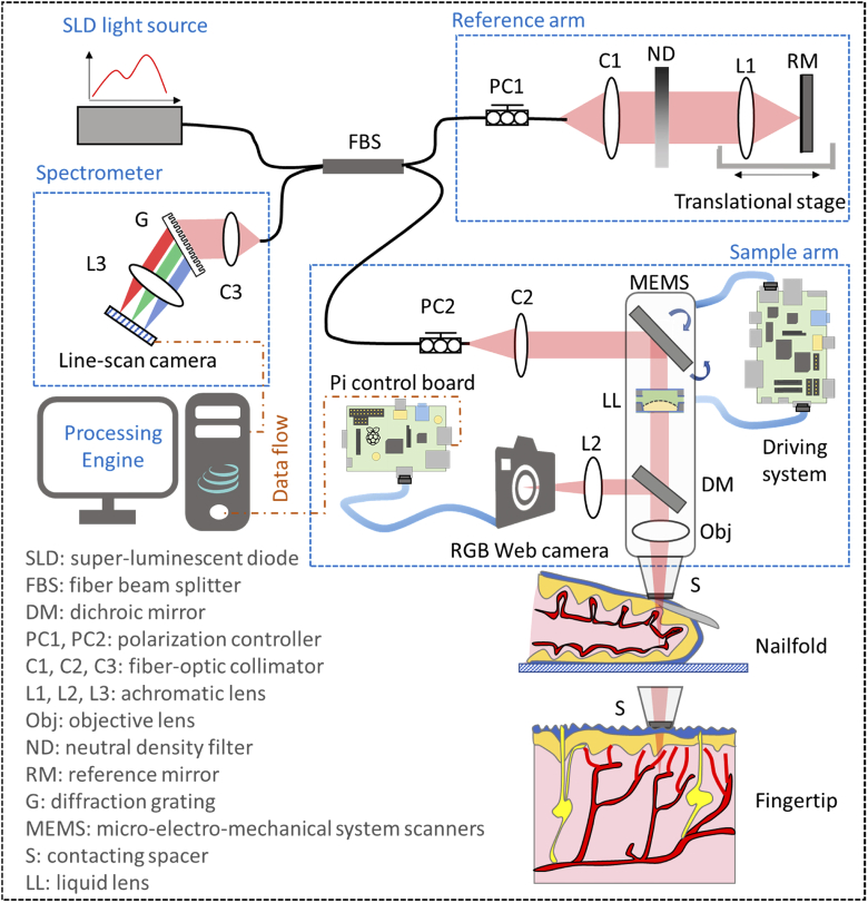
The schematic setup of spectral-domain GD-OCM system is shown in Fig. 1. The light source is a broadband super-luminescent diode (cBLMD-D-840-HP, Superlum Diodes Ltd.) with a center wavelength of 840 nm and a bandwidth of 120 nm, corresponding to an axial resolution of ∼2 µm in tissue. The fiber beam splitter splits light from the source into a reference arm and a sample arm. A linear stage was adopted in the reference arm to adjust the optical path length, and a variable neutral density filter was utilized to control the reflected spectral intensity. In the sample arm, the light beam was scanned by a micro-electro-mechanical system (MEMS) scanner (Mirrorcle Technologies, Inc.) [19], and dynamically focused into the tissue by incorporating a liquid lens and an objective lens [20]. The corresponding lateral resolution was measured to be ∼2 µm over a depth in tissue of 1.5 mm. Light reflected from the two arms interfered at the coupler and then was detected by the spectrometer incorporated with a line-scan CMOS camera (OctoPlus, Teledyne e2v). The detected interference signal was then processed in the engine through k-space linearization, dispersion compensation, and Fourier transformation [21]. Additionally, the back-reflected photons from the tissue were partially collected by a 2D RGB camera through a dichroic mirror, which sent a real-time video to the engine to ensure reproducibility and usability in clinical imaging scenarios.
Fig. 1.
Schematic of the GD-OCM instrument used for imaging the vasculature of human skin.
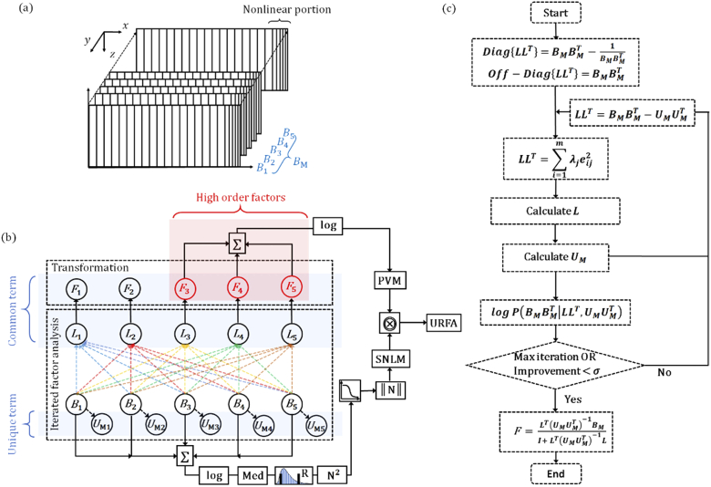
To image the 3D vasculature of a human nailfold, the scanning protocol consisted of 2 500 B-frames with 580 A-lines in each B-frame, as schematically shown in Fig. 2(a). The speed of the line-scan camera was controlled at 50 kHz with a programmed exposure time of 19.3 µs. At one cross-sectional location, the B-frame scanning was repeated 5 times with a frame rate of 50 frames per second and a duty cycle of ∼50%, resulting in a total acquisition time of 50 seconds. The MEMS scanning along the fast direction (x-direction) was designed following a quasi-linear forward movement with the nonlinear portion < 20% and a fast fly-back movement with the time cost corresponding to 1/3 of the forward movement. The lateral sampling of the dataset was 580 (x-direction) × 500 (y-direction), which covered a field of view of 1 × 1 mm. To further visualize the peripheral capillary loops, certain regions of interest are zoomed in to 0.5 × 0.5 mm with sample spaces equal to or smaller than 1 µm, matching the Nyquist sampling of the adopted GD-OCM system with 2 µm lateral resolution.
Fig. 2.
Scanning protocol and URFA processing flow. (a) Schematic diagram of the scanning protocol, in which the nonlinear portions of MEMS scanning are denoted by the dense and unequally spaced samples at the end of each frame. : 5 repeated B-frames. (b) OCT angiography processing pipeline for the ultrahigh-resolution factor angiography (URFA). : factor loadings, : anisotropic unique variance, : factors. The common term including L and F, and the unique term U are marked in blue shadings respectively. The high order factors are marked in red shading. ∑: pixel-wise summation, log: logarithmic scale compression, Med: median pooling, R: rescaling, N2: calculation of square power, ‖N‖: normalization,  : reversed sigmoid function, ⨷: pixel-wise multiplication. (c) An illustrative flow chart describing the iterated factor analysis and transformation. Diag{} and off-Diag{}: diagonal and off-diagonal elements of a matrix that are defined by corresponding elements of the second matrix, : the process of singular value decomposition to estimate L, logP: log-likelihood probability, : pre-defined tolerance, I: identity matrix.
For a typical adult human, the respiratory rate is about 14 breaths per minute, and the heartbeat rate is about 70 beats per minute. Accordingly, a 3D scanning may be affected 12 times by respiratory motion and 58 times by cardiac motion over the 50 seconds acquisition period. It may also be affected by other uncontrollable and unintended skin movements, ranging from faster jerking tics to longer tremors and seizures. As schematically shown in Fig. 1, both dorsal side (i.e., nailfold) and ventral side (i.e., fingertip) of human finger skin are imaged, in which the latter position may be less affected by the repeated motion due to close surface-to-surface contact with the spacer. This study was reviewed and approved by the Institutional Review Board for LighTopTech Corp.
2.2. Ultrahigh-resolution factor angiography (URFA)
2.2.1. URFA processing pipeline
The proposed URFA processing pipeline is shown in Fig. 2(b). First and foremost, the n times repeated (n = 5 in this work) B-frames are linearly fitted as a common term that is a matrix multiplication between factors of dimension m × s (m represents the number factors and s represents the number of samples), factor loadings of dimension n × m, and an addictive unique term with anisotropic means and variances for individual frames. To ensure the accuracy of fitting, factor analysis is processed iteratively by maximizing a combined log-likelihood probability of the common term and the unique term [22]. Second, when the linear fitting is optimized, high orders of factors (typically orders > 2) are selected and back-transformed into space domain. The high orders cutoff of 2 is related to the tissue scattering properties and the MEMS scanning speed, and was empirically selected by visualizing the factors in 3D view. The corresponding space domain images are further summated and logarithmic-scale compressed as a primary vasculature map (PVM). The iterated factor analysis and transformation will be detailed in section 2.2.2.
Essentially, OCTA can be regarded as a high-dimensional 2-class (static structure and dynamic blood flow) classification task, in which the obtained linear hyperplane from factor analysis may not well approximate the classifier. This can be understood considering that, apart from the variance caused by floating scatters (e.g., blood cells), a typical OCTA signal is also related to the absolute intensity of OCT signal [23], and may also be affected by the saturation of decorrelation if a long time interval (e.g., a typical B-frame interval of several to tens of milliseconds) is utilized, resulting in certain degrees of nonlinearity in the classification. In URFA, to deal with this issue, we designed a soft nonlinear mask (SNLM) with the averaged structure image through step-by-step nonlinear operations/transformations as in Fig. 2(b), including logarithmic-scale compression, rescaling of structure to exclude noisy background, stride 1 median pooling (calculating median pixel value of the selected kernel) with a kernel size of 3 × 3 pixels, calculation of square power, logistic regression with a reversed sigmoid function, and normalization. The calculation of SNLM is detailed in Eq. (12) in section 2.2.3. Finally, the URFA image is calculated via a pixel-wise multiplication between the PVM and the SNLM.
2.2.2. Iterated factor analysis and transformation
The processes of iterated factor analysis and transformation are further illustrated as a flow chart in Fig. 2(c). Initially, the repeated B-frames are rearranged as a 2D matrix , in which each B-frame is serialized by concatenating the contained A-lines. As a repeated collection of large independent samples of tissue reflections from multiple spatial locations, the follows a multivariate Gaussian random process, which may be further described through a generative latent variable model as:
| (1) |
where represents the common variance, meaning that only the variance shared among all B-frames are accounted for; S represents the specific variance, i.e., the unshared variance in specific frames, such as tissue motion; and represents the residual error variance from the measurement.
In the factor analysis, the specific variance and the residual error variance are modeled jointly and can be further generalized as an anisotropic unique variance. This unique variance represents the additive variance without correlations due to non-repeatability or random measurement errors. For a typical Fourier domain OCT system working in the shot noise-limited regime, the unique variance is mainly contributed by the specific variance (i.e., tissue motion) as compared to the random error variance (i.e., system noise). Practically, it’s also reasonable to model the tissue motion in individual frames as anisotropic variance, as the frame-specific motions are spatial-temporally independent and with various intensities. On the other hand, the common variance can be calculated as a multiplication between the common factor matrix F and the corresponding factor loadings L. Therefore, the generative latent variable model in Eq. (1) can be rewritten as:
| (2) |
in which, F represents a matrix of m unobserved latent variables with each row indicates an independent factor ; L represents a n × m matrix of the factor loadings with its column vectors indicating the influence of one factor component on each scanned frame; each non-zero element in represents an anisotropic unique variance following a Gaussian distribution, which centers at the sample mean of each B-frame. Such latent variable model is named “generative” because it describes how is generated from F by seeking the linear combinations of the common factors in F. A matrix expression of Eq. (2) is expressed as:
| (3) |
For the matrices herein, s denotes the index of pixel samples in one B-frame; i and j denote the row and the column indexes of the matrices, respectively. The exploratory factor analysis adopted in URFA is superior to other unsupervised learning models such as PCA, since PCA does not generally model the unique variance separately or only models an isotropic variance as in probabilistic PCA [22,24].
In order to identify the factors that produce correlations among the B-frames and extract the blood flow information corresponding to relatively low levels of inter-frame correlations, a covariance matrix is constructed as:
| (4) |
According to the definitions of the common variance and the unique variance, F and are statistically independent. Additionally, in order to separate the static factor and the dynamic factor, without loss of generality, the factor axes are assumed to follow a varimax rotation, which means the variance of the squared loadings of L on all the factors of F are maximized. Therefore, the factors in F are also independent of each other, i.e., F is an orthogonal matrix. The covariance matrix in Eq. (4) can be derived as:
| (5) |
where = is a m × m identity matrix of the m factors, is the covariance of described as a n × n anisotropic diagonal matrix . A matrix expression of Eq. (5) is written as:
| (6) |
Rearranging Eq. (5) as , the loading matrix L may be estimated through a principal factor method. First, the off-diagonal elements in is directly calculated as the B-frame covariances . Second, the diagonal elements can be initialized as , since normally is a non-singular matrix with an existing inverse. Alternatively, the diagonal elements can be replaced by the largest covariance in the i-th row of . With the pre-defined , the calculation of L is equivalent to finding the orthogonal matrix of through singular value decomposition, expressed as:
| (7) |
where the elements in the factor loading L are expressed as . From another perspective, the diagonal elements of are updated with a better estimation as . Therefore, the principal factor method can be iterated to increase the modeling accuracy, with an improved estimation of L and after each iteration.
As an evaluation of the accuracy, an objective function is designed with the summation of log-likelihood probabilities of the common variance and the unique variance as:
| (8) |
where represents the log-likelihood of the common variance, represents the log-likelihood of the unique variance, accounts for the residual fitting loss in the singular value decomposition, and is a bias constant term. In URFA, the number of factors (m) is a user-defined input parameter, which is typically set as , in consideration of the computation time cost and the capability of resolving blood vessels. In current scenario of OCT angiography with a small number of repeated B-frames (n = 5), m is equal to the B-frame repeats n, therefore res ≡ 0.
The convergence of the modeling is reached at iteration N, if either of the following conditions is satisfied:
-
1)the improvement of the fitting is smaller than a pre-defined tolerance , calculated as:
(9) -
2)
the maximum number of iterations is reached, as N > Nmax.
Practically, the tolerance is set as 0.01, and Nmax is set as 100. Finally, the optimized L and are the ones obtained from the last iteration. This is equivalent to the maximization step of the classical expectation–maximization (EM) algorithm, which computes the parameters that maximize the expected log-likelihood.
By additionally performing an expectation step of the EM algorithm with the optimized L and , the cross-sectional images of the separated factor components can be calculated as
| (10) |
where represents the expectation of the back-transformed factor components in the common variance, and I is the identity matrix. One thing to notice is that in Eq. (10) the inversions of matrices are only performed for a relatively small m × m matrix () and a diagonal n × n matrix (), which should be trivial to compute. The rows of are arranged in the descending order of correlations, with the leading factors mainly contributed by the static tissue structure of highly correlated signals, and the remaining factors mainly contributed by blood flow with relatively low correlations.
The cross-sectional PVM is calculated by summing the absolute values of the images corresponding to high order factors (orders larger than 2), and logarithmic-scale compressed as:
| (11) |
2.2.3. Nonlinearity in URFA
In order to correct the misclassification due to nonlinearity, the corresponding cross-sectional SNLM is designed following equation:
| (12) |
in which is the rescaled logarithmic-scale structure image, represents the strid 1 median pooling, and represents a kernel size of 3 × 3 pixels.
The entire URFA processing can be summarized as:
| (13) |
where ⨷ represents the pixel-wise multiplication.
2.2.4. Additional steps for comparison and visualization
For comparison, another algorithm based on differential speckle variance (DSV) [4,25,26] that has been widely used for translation of clinical OCTA [27,28] is also utilized to process the same dataset. For fair comparison, the nonlinear misclassification in DSV is also handled by pixel-wise multiplication with the same SNLM.
After OCTA processing, the repeated B-frames are averaged to enhance the visualization of tissue structure. The resulting OCT and OCT angiography B-frames are stacked into 3D volumes, which are further sliced and/or averaged as en face view projections. In the en face view OCTA images, the motion artifacts, as projections of the de-correlated noisy background, may appear as bright lines along the fast-scanning direction.
3. Results
3.1. Cross-sectional vasculature processed with URFA
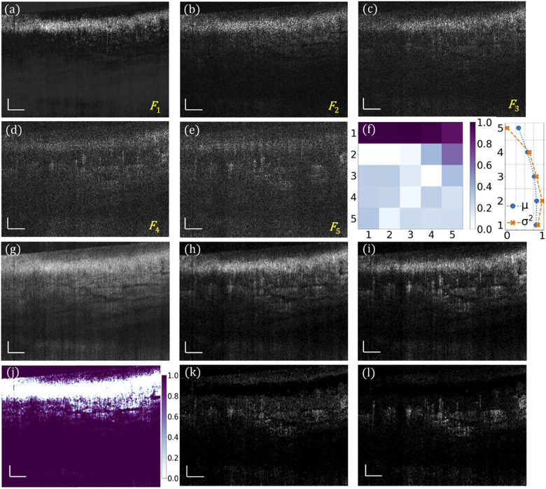
Obtained with the URFA processing, Fig. 3(a) – (e) are five representative factor components of the common variance from an imaged human nailfold, arranged in the descending order of correlations. Figure 3(a) represents the static factor component, which is mainly from the tissue structure. Figure 3(b) represents the boundary component, which is a mix of static and dynamic factors. Typically, this second component should also be excluded from skin URFA, as the skin tissue has high optical scattering, resulting in a residual structure that overshadows the blood flow in (b). Figure 3(c) – (e) represent three dynamic factor components that have higher content of signals from dynamic blood flow. Since the tissue features (represented by common variance) and their spatial-temporal motion (represented by unique variance) are essentially independent, these two components can be separated in the factor domain of URFA. In this domain of multiple orthogonal factors, the common component is represented by a normalized covariance matrix as shown in Fig. 3(f, left), corresponding to a matrix multiplication of factor loadings ; and the unique variance is represented by anisotropic Gaussian distributions of tissue motion in each frame, with the normalized mean µ and variance σ2 shown in Fig. 3(f, right). Figure 3(g) is the log-scale average of the B-frames corresponding to an enhanced visualization of tissue structure. The cross-sectional dynamic blood flow processed by DSV is displayed in Fig. 3(h). The corresponding cross-section processed by URFA, as a log-scale summation of the absolute flow components in (c) – (e), is displayed in Fig. 3(i). The noisy background in (i) is much weaker than that in (h), which is ascribed to the advantage of excluding motion-induced anisotropic unique variance in URFA. Derived from Fig. 3(g), a cross-sectional soft non-linear mask (SNLM) is calculated and shown in Fig. 3(j). In (j), the largely reduced background signal was mainly located in the epidermis layer that is free of blood vessels. The final OCTA cross-sectional images by DSV and URFA are achieved by handling the nonlinearity through pixel-wise multiplication with the calculated SNLM, as shown in Fig. 3(k) and Fig. 3(l), respectively. Compared with (h) and (i), with further management of the nonlinear misclassification, images (k) and (l) provide better visualization of blood vessels with reduced intensity of static background.
Fig. 3.
URFA processing of representative B-frames in vivo. (a) - (e) Back-transformed five factor components F of the common variance from human nailfold B-frames, arranged in descending order of correlations, labelled as F1 – F5. (f) Normalized covariance matrix of the common variance in factor domain (left), and normalized mean µ and variance σ2 of the unique variance . (g) Log-scale frame averaged structure image. (h) Log-scale blood flow image processed with DSV before handling nonlinearity. (i) Log-scale blood flow image obtained with URFA before handling nonlinearity, named as primary vasculature map (PVM) in section 3.2.1. (j) Soft nonlinear mask (SNLM) obtained from the structure in (g). (k) Log-scale blood flow image processed with DSV after handling nonlinearity with SNLM. (l) Log-scale blood flow image processed with URFA after handling nonlinearity with SNLM. All scale bars: 100 µm.
3.2. En face vasculature processed with URFA
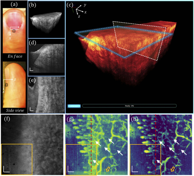
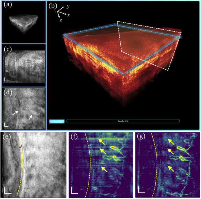
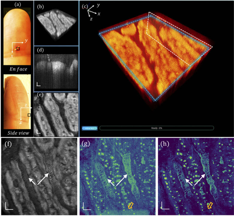
En face view and side view photographs of a human left ring finger are shown in Fig. 4(a), in which the nailfold region of 1 × 1 mm2 marked by a black square was imaged with the GD-OCM system, and the obtained 3D volume was rendered in our cross-platform 4D viewer. The 3D visualization of the scanned nailfold tissue is displayed in Fig. 4(b), which is further zoomed-in and color-coded in Fig. 4(c). At a slow-scanning cross-section indicated by a white box in (c), a representative high-resolution image is displayed in Fig. 4(d), revealing rich epidermis and dermis features. Additionally, by slicing through the papillary dermis layer, as denoted by the blue box in (c), the en face view image is shown in Fig. 4(e), corresponding to a depth of ∼ 12 µm. An averaged tissue structure of all depths is shown in Fig. 4(f), and the en face view OCTA images processed by DSV and URFA are displayed in Fig. 4(g) and (h) respectively, showing the delineated vasculature network, in which the red dashed lines indicate the B-frames in Fig. 4(k) and (l). In (g), the vasculature pattern of dynamic blood flow is readily delineated. However, due to the existence of tissue motion, the resulted artifacts may affect the visualization of local perfusion. Moreover, those motion artifacts, as false positive labels of blood vessels, would affect the quantitative results of the vasculature pattern if evaluated with machine recognizable matrices (e.g., vessel area density). Additionally, in the acquisition of each B-frame, the MEMS scanner may slightly oscillate at the end of the forward movement, resulting in additive noise, as indicated by the hollow orange arrow (bottom). In contrast to these, as shown in (h), with URFA-based OCTA processing, both the vertical line artifacts from tissue motion and the residual noise from MEMS oscillation are minimized, providing significant improvement in capillary visualization, as denoted by the white arrows.
Fig. 4.
Visualizations of human nailfold tissue imaged with GD-OCM. (a) Photographs of the top view and the side view of the dorsal side finger, with the region of scanning marked by a black square. (b) 3D visualization of the nailfold tissue. (c) Enlarged and color-coded 3D visualization, with a white box indicating (d) a cross-sectional B-frame and a blue box indicating (e) an en face view slice averaged over a depth of 12 µm. (f) All depth averaged en face view image. (g) En face view OCTA image processed with DSV. (h) En face view OCTA image processed with URFA. In (g) and (h), the white arrows indicate capillaries better resolved from noisy background if processed with URFA. The orange hollow arrows indicate noise from oscillating MEMS scanner. The red lines indicate projections of the B-frames in Fig. 3(k) and (l). All scale bars: 100 µm.
To better visualize the capillary loop, a 0.5 × 0.5 mm2 region marked by orange squares in Fig. 4(f) – (h) was further imaged with 1 µm sampling with 500 × 500 A-line samples to match the optimal lateral resolution of 2 µm. The corresponding 3D visualization is displayed in Fig. 5(a) and (b), and the cross-sectional and en face slices are respectively shown in Fig. 5(c) and (d), in which the cellular structures along the aligned collagen fibers are visualized as indicated by the white arrows, which may be fibroblasts of different sizes. As the most common cells in the connective tissue, fibroblasts are typically large spindle-shaped cells with oval nuclei. The all-depth averaged en face view is shown in Fig. 5(e), where the boundary between the nail plate and the nailfold soft tissue is demarcated by a dashed curve. Correspondingly, Fig. 5(f) and (g) depict the en face views of the nailfold vasculature obtained with DSV and URFA, respectively. The hairpin “U”-shape capillary loops are readily delineated, indicating the arteriole end and the venule end of a capillary running parallel to the nailfold surface. However, compared with the vasculature pattern in (g), the motion-induced artifacts in (f), appearing as bright horizontal line defects (denoted by the yellow arrows), severely undermine the visualization of the capillary loops. The number of resolved capillary loops is about 6 within the 0.5 mm nailfold tissue, which agrees well with the reported anatomical findings, i.e., the density of nailfold capillaries is about 9 - 12 per mm [29,30].
Fig. 5.
High-resolution imaging of the 0.5 × 0.5 mm2 human nailfold tissue with GD-OCM. (a) 3D visualization of tissue. (b) Enlarged and color-coded 3D visualization, with a white box indicating (c) a cross-sectional B-frame, and a blue box indicating (d) an en face view slice of 12 µm. (e) All depth averaged en face view image. (f) En face view OCTA image processed with DSV. (g) En face view OCTA image processed with URFA. In (e) – (g), the yellow dashed curves indicate the boundary between the nail plate and the nailfold soft tissue. In (f) and (g), the yellow arrows indicate projected motion artifacts. All scale bars: 50 µm.
3.3. Multi-zone vascular imaging with URFA and cascaded group-wise registration
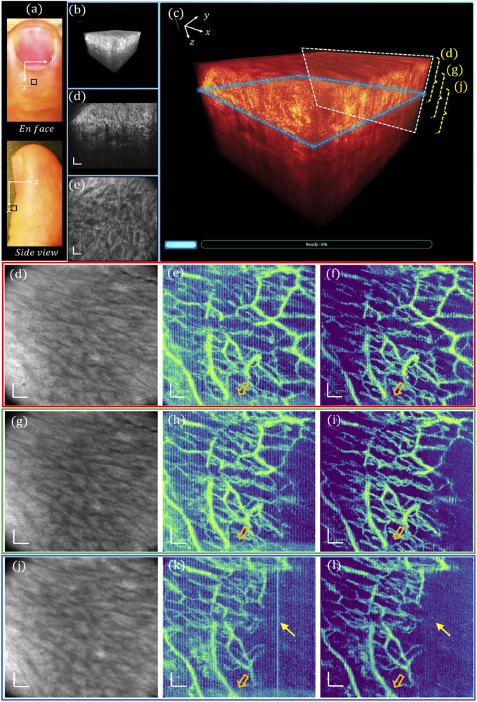
In addition to the high lateral resolution, another key advantage of GD-OCM is the digitally-controlled dynamic focusing system enabled by a fast liquid lens. This feature efficiently extends the depth of OCM imaging field, to the benefit of visualizing deep vasculature in the reticular dermis. In order to test the multi-zone capillary imaging with dynamic refocusing, we imaged dorsal skin of the same finger at 5 mm away from the nail over a field of view of 1 mm2, shown in Fig. 6(a). The corresponding 3D visualization, re-rendered color-coded 3D visualization, representative cross-section and en face view slice are respectively shown in Fig. 6(b) – (e). As indicated by the right brackets in (c), the all-depth averaged projections of three different zones are shown in Fig. 6(d), (g) and (j), respectively. Processed with DSV, the OCTA images with repeated motion artifacts mainly due to human heartbeat are visualized in Fig. 6(e), (h) and (k). In comparison, Fig. 6(f), (i) and (l) depict the en face view mean intensity projections of the vasculatures obtained from the same dataset with URFA. The motion artifacts are largely reduced with URFA, as representatively denoted by the yellow arrows in (k) and (l); this motion reduction can be credited to separately modeling the motion as anisotropic unique variance. The motion noise from oscillating MEMS in DSV-based OCTA and the counterpart region in URFA-based OCTA are indicated by the hollow arrows, respectively.
Fig. 6.
Visualizations of human skin at multiple depths. (a) Photographs of the top view and the side view of the human finger, with the region of scanning marked by a black square. (b) 3D visualization of the skin tissue. (c) Enlarged and color-coded 3D visualization, with a white box indicating (d) a cross-sectional B-frame, and a blue box indicating (e) an en face view slice averaged over a depth of 12 µm. (d), (g) and (j) All depth averaged en face view images corresponding to the 3 zones along the depth denoted by the dashed brackets in (c). (e), (h) and (k) En face view OCTA images processed with DSV. (f), (i) and (l) En face view OCTA images processed with URFA. In (e), (f), (h), (i), (k) and (l) the orange hollow arrows indicate noise from oscillating MEMS scanner. In (k) and (l), the yellow arrows indicate a bright line motion artifact if processed with DSV, which is removed with URFA. All scale bars: 100 µm.
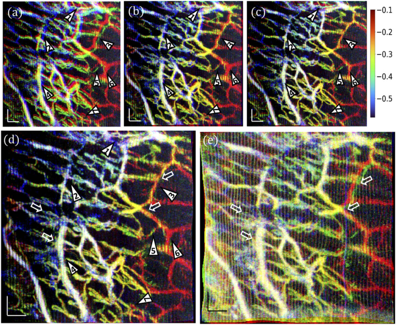
Due to the long time interval between sequential volumetric acquisitions and savings (∼1.5 min), multiple continuously scanned OCTA volumes may not be laterally matched because of motion-induced distortions, such as shift, expand/contract, twist, or rotation. The corresponding mismatches in the vasculature can be visualized by overlaying Fig. 6(f), (i) and (l) as red, green, blue colors in Fig. 7(a). To correct such mismatches, we adopted an automated motion compensation method [18,31] by means of cascaded group-wise affine registration and B-spline registration. The cascaded group-wise registrations are designed as a set of stacked transforms, each of which is applied independently to a single en-face view image. In consideration of the memory consumption and registration time, 3 resolution scales corresponding to grid spaces of 16, 8, and 4 pixels are utilized for both the affine registration and B-spline registration. The registration process is optimized through adaptive stochastic gradient descent method [32], with 10 000 random spatial samples in each iteration and a maximum of 256 iterations. The registration was optimized upon a similarity metric that minimizes variance of en-face images under the constraint that the average deformation over images should be zero [33].
Fig. 7.
Affine and B-spline registrations of skin vasculatures at multiple depths. (a) An overlay of the en face view OCTA images processed with URFA, corresponding to Fig. 6(f) red, (i) green, and (l) blue. (b) The overlayed vasculature after group-wise affine registration. (c) The overlayed vasculature after group-wise B-spline registration. (d) The overlayed vasculature after cascaded group-wise affine and B-spline registrations. The numbered triangles 1–7 indicate representative regions with improved vessel visualization after registration; in particular, triangles 2, 3, 6 indicate vessels with better quality after B-spline registration, and triangle 5 indicates that after affine registration. (e) A registered overlay of the en face view OCTA images processed with DSV, corresponding to Fig. 6(e) red, (h) green, and (k) blue. In (e), white hollow arrows indicate vessels presenting false dilation, blurring, and mismatches caused by motion artifacts in the registration, as compared with (d). The physical depths of the blood vessels are approximately indicated by the color bar (with white representing vessels existing in all three layers), counted starting from the top surface of the skin, in millimeters. All scale bars: 100 µm.
In order to analyze the effectiveness of the registration strategy, additionally, we applied group-wise affine registration and group-wise B-spline registration separately, as shown in Fig. 7(b) and (c), respectively. Compared with the original overlay in (a), most mismatches are corrected after affine registration in (b), as representatively denoted by the numbered triangles. However, as indicated by No. 2, 3, and 6, diameters of blood vessels may be overestimated due to slight mismatches from subtle non-rigid movement, which is better handled by the B-spline based free-form registration in (c). At the same time, without the macroscale control of affine registration, the B-spline registration may misinterpret the spatially isolated images of the same blood vessel as multiple vessels, as indicated by triangle No. 5. Likely, these two issues can be solved by building a cascaded group-wise registration with both affine and B-spline registrations, as shown in Fig. 7(d), resulting in a clear co-registered vasculature. In striking contrast, if the aforementioned registration steps are applied to the vascular images in Fig. 6(e), (h), (k), as processed by DSV, most vessels can still be co-registered, but with significant false dilation, blurring, and failures in registration, as shown in Fig. 7(e) and representatively denoted by the white hollow arrows. The physical depths of the blood vessels in (a) – (e) are indicated by the color bar approximately, counted starting from the top surface of the skin, in millimeters.
3.4. Vascular imaging of other normal and diseased skin sites with URFA
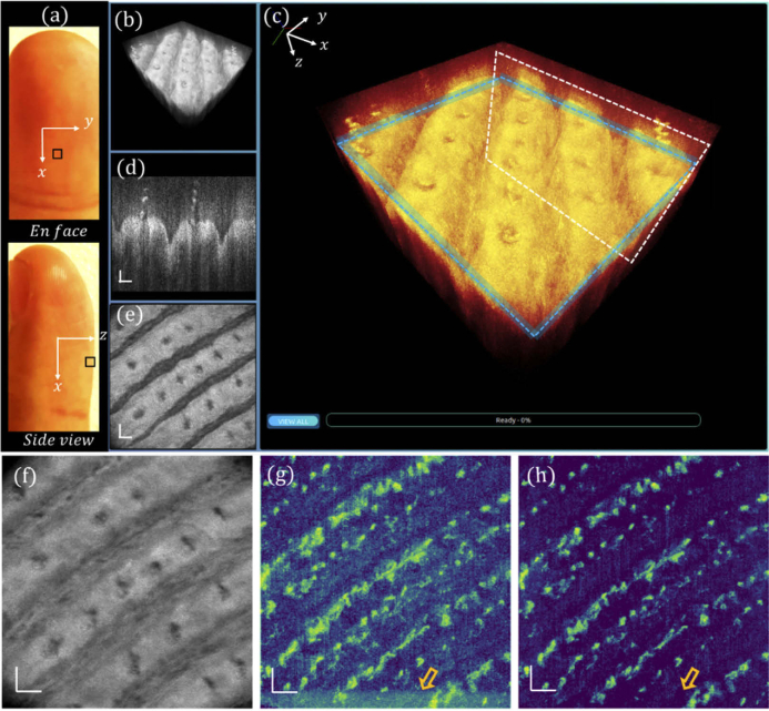
Multiple skin sites are further imaged to evaluate the robustness and reliability of the proposed URFA method. Figure 8(a) depicts the en-face view and side view photos of the ventral left middle finger, in which the fingertip region marked by a black square is imaged by the GD-OCM system. The corresponding 3D visualization, re-rendered color-coded 3D visualization, representative cross-section, and en face view slice are respectively shown in Fig. 8(b) – (e). The all-depth averaged projection is shown in Fig. 8(f). As compared between DSV in Fig. 8(g) and URFA in Fig. 8(h), both resulting OCTA images are largely free of line-shape motion artifacts, mainly ascribed to the close contact of the probe spacer with skin surface. However, the noise from microtremors and MEMS oscillation, as denoted by the hollow arrow in (g), would still undermine the visualization of blood vessels with a relatively low contrast to noise ratio, while the corresponding URFA image in (h) is largely unaffected.
Fig. 8.
Visualizations of human fingertip tissue in normal status. (a) Photographs of the top view and the side view of the ventral side middle finger, with the region of scanning marked by a black square. (b) 3D visualization of the tissue. (c) Enlarged and color-coded 3D visualization, with a white box indicating (d) a cross-sectional B-frame, and a blue box indicating (e) an en face view slice of 12 µm. (f) All depth averaged en face view image. (g) En face view OCTA image processed with DSV. (h) En face view OCTA image processed with URFA. In (g) and (h), the orange hollow arrows indicate noise from oscillating MEMS scanner. All scale bars: 100 µm.
Furthermore, a wounded index finger after a knife injury is shown in Fig. 9(a), in which the fingertip region marked by a black square is imaged by the GD-OCM system. The corresponding 3D visualization, re-rendered color-coded 3D visualization, representative cross-section and en face view slice are respectively shown in Fig. 9(b) – (e). The all-depth averaged projection, OCTA images processed by DSV and URFA are respectively shown in Fig. 9(f) – (h). Similar to Fig. 8, the contrast to noise ratio of OCTA is largely improved if processed with URFA. Compared with that in Fig. 8, in Fig. 9 the distribution of blood vessels is much denser with an irregular pattern. This can be explained by the fact that, during the wound healing process, new blood vessels would form through an angiogenesis process that brings nutrients, immune cells and oxygen to facilitate the recovery. Additionally, microorganisms, immune cells, and intercellular fluid may accumulate and float in the gaps of wound, appearing as layers of bright biofilms in OCTA images, as indicated by the arrow clusters in (f) – (h).
Fig. 9.
Visualizations of human fingertip tissue with knife injury. (a) Photographs of the top view and the side view of a ventral side wounded index finger, with the region of scanning marked by a black square. (b) 3D visualization of the tissue. (c) Enlarged and color-coded 3D visualization, with a white box indicating (d) a cross-sectional B-frame, and a blue box indicating (e) an en face view slice of 12 µm. (f) All depth averaged en face view image. (g) En face view OCTA image processed with DSV. (h) En face view OCTA image processed with URFA. In (g) and (h), the orange hollow arrow indicates noise from oscillating MEMS scanner, and the white arrow clusters indicate biofilm and interstitial fluid accumulated in the wound. All scale bars: 100 µm.
As the blood vessels are generally interconnected, in the absence of any motion artifacts, the adjacent B-frames in the OCTA dataset should still possess some level of correlation, leading to a locally smooth change of the frame averaged intensity profile. Therefore, the local difference of the intensity profile can be used to evaluate how severely the motion artifacts affect the angiography results. Practically, the local variation can be calculated as:
where fN represents the number of B-frame positions (fN = 400 in this example), represents a normalized pixel-averaged OCTA B-frame, and represents the absolute value of the subtraction between adjacent . As evaluated by the local differences of all images, a significant reduction of motion artifacts is achieved with the newly designed URFA algorithm, as compared with the widely-accepted DSV algorithm, as shown in Table 1. The improvement is about 49.6% on average.
Table 1. Quantitative local differences of OCTA images in Figs. 4, 5, 6, 8, and 9, compared between DSV and URFA.
| Vasculature pattern | Local difference (%) |
|
|---|---|---|
| DSV | URFA | |
| Fig. 4(g) and (h) | 1.27 | 0.88 |
| Figure 5(f) and (g) | 3.99 | 1.07 |
| Fig. 6(e) and (f) | 2.55 | 1.09 |
| Figure 6(h) and (i) | 2.22 | 0.89 |
| Fig. 6(k) and (l) | 2.11 | 0.90 |
| Figure 8(g) and (h) | 0.66 | 0.39 |
| Fig. 9(g) and (h) | 0.65 | 0.47 |
4. Discussion and conclusion
In this paper, we reported an innovative 3D flow imaging technique for high-resolution motion-insensitive OCTA imaging in vivo. This method based on exploratory factor analysis matches very well with ultrahigh-resolution OCM angiography, which is easily affected by involuntary tissue motion due to small spot size, short Rayleigh distance, and narrow point spread function of the system, as well as the dense lateral sampling. Although demonstrated on a high-resolution system, the present URFA algorithm is equally applicable to datasets from other OCTA systems with less rigorous requirements of image resolution. We have also successfully applied URFA to OCTA images acquired without any motion stabilizer (e.g., contacting spacer or chinrest), and observed a comparable reduction in motion relative to DSV. The exploratory factor analysis assumes that implicit features (e.g., static structure, blood flow) are responsible for the features of the dataset. From this perspective, it is believed to be superior to principal component analysis (PCA)-based OCTA approaches [26], as PCA only explains the variance of the data through regressions on the repeated frames, without considering the latent features/factors or separately modeling the motion. On the other hand, the high numerical aperture and dynamic refocusing of GD-OCM system would also mitigate the shadowing defects (or projection artifacts) by means of rejecting multiple scattered photons [34]. Therefore, the present OCM system and URFA technique would potentially facilitate 2D and 3D quantitative analyses of the vasculature patterns [35] with reduced artifacts of both motion and shadow.
With optimized frame intervals, regions of cellular/subcellular dynamics and capillaries can potentially be imaged in a single scan in order to investigate the vessel-cell interactions. This future plan may need additional efforts in super resolution [36,37], noise reduction [2,34], and cell segmentation [38] for better delineation of individual cells, which are, however, beyond the scope of the current topic for motion-insensitive OCTA.
One possible limitation of the URFA processing is that biased darkness may exist in the regions with extremely severe motion artifacts together with dense vessels aligned along the fast-scanning direction. However, this scenario is relatively rare, as the blood vessels, especially capillaries, usually function as an interconnected network instead of individual vessels along the same direction. And even if this geometry occurred, such biases can be further alleviated and overcome by simply fusing multiple volumes with the readily applied registration technique demonstrated in Fig. 7. Moreover, in quantitative vascular studies where adaptive pre-processing is commonly adopted [35], the regional darkness is less of an issue compared to the line artifacts caused by motion.
The time cost of URFA processing takes about 2.6 min for each 500 (x - direction) × 500 (y - direction) × 400 (depth) × 5 (repetitions) OCT volume, processed on a Linux desktop with i9-7900X @3.30 GHz and 64 GB memory. Additionally, the processing can be easily divided into frame-level subgroups for parallel computing, whose cost will be dramatically reduced as the number of CPU cores increases. Further improvement should also be viable by parallel processing with GPU engines.
In conclusion, we developed an in vivo OCTA technique named URFA. By modeling the repeated scans as generative latent variables that are iteratively fitted through exploratory factor analysis, the motion artifacts in specific frames, as represented by anisotropic unique variance, can be separated and removed from the common variance. Meanwhile, the static structure and blood flow in the common variance are decoupled in the factor domain of the exploratory factor analysis. Finally, the transformed frames of dynamic blood flow are differentiated from both static structure and the separately modeled motion, resulting in motion-insensitive OCTA images. While this first demonstration of URFA was on human skin, this angiography technique and the associated multi-zone registration technique described herein should be equally applicable to other organs in vivo such as eye [39,40] and brain [3,26]. The reduction of motion artifacts for vascular imaging in vivo and in situ would speed up the clinical translation of the present techniques from benchmark to bedside.
Disclosures
CC: LighTopTech Corp. (I,E,P), WW: LighTopTech Corp. (E,P), AC: LighTopTech Corp. (E,P).
Data availability
Data underlying the results presented in this paper are not publicly available at this time but may be obtained from the authors upon reasonable request. Requests for the data sharing should be addressed to the corresponding author.
References
- 1.Spaide R. F., Fujimoto J. G., Waheed N. K., Sadda S. R., Staurenghi G., “Optical coherence tomography angiography,” Prog. Retinal Eye Res. 64, 1–55 (2018). 10.1016/j.preteyeres.2017.11.003 [DOI] [PMC free article] [PubMed] [Google Scholar]
- 2.Liba O., Lew M. D., Sorelle E. D., Dutta R., Sen D., Moshfeghi D. M., Chu S., De La Zerda A., “Speckle-modulating optical coherence tomography in living mice and humans,” Nat. Commun. 8(1), 1–13 (2017). 10.1038/s41467-016-0009-6 [DOI] [PMC free article] [PubMed] [Google Scholar]
- 3.Vakoc B. J., Lanning R. M., Tyrrell J. A., Padera T. P., Bartlett L. A., Stylianopoulos T., Munn L. L., Tearney G. J., Fukumura D., Jain R. K., Bouma B. E., “Three-dimensional microscopy of the tumor microenvironment in vivo using optical frequency domain imaging,” Nat. Med. 15(10), 1219–1223 (2009). 10.1038/nm.1971 [DOI] [PMC free article] [PubMed] [Google Scholar]
- 4.An L., Qin J., Wang R. K., “Ultrahigh sensitive optical microangiography for in vivo imaging of microcirculations within human skin tissue beds,” Opt. Express 18(8), 8220 (2010). 10.1364/OE.18.008220 [DOI] [PMC free article] [PubMed] [Google Scholar]
- 5.Jonathan E., Enfield J., Leahy M. J., “Correlation mapping method for generating microcirculation morphology from optical coherence tomography (OCT) intensity images,” J. Biophotonics 4, 583 (2010). 10.1002/jbio.201000103 [DOI] [PubMed] [Google Scholar]
- 6.Jia Y., Tan O., Tokayer J., Potsaid B., Wang Y., Liu J. J., Kraus M. F., Subhash H., Fujimoto J. G., Hornegger J., Huang D., “Split-spectrum amplitude-decorrelation angiography with optical coherence tomography,” Opt. Express 20(4), 4710 (2012). 10.1364/OE.20.004710 [DOI] [PMC free article] [PubMed] [Google Scholar]
- 7.Gong P., Li Q., Wang Q., Karnowski K., Sampson D. D., “Jones matrix-based speckle-decorrelation angiography using polarization-sensitive optical coherence tomography,” J. Biophotonics 13, e202000007 (2020). 10.1002/jbio.202000007 [DOI] [PubMed] [Google Scholar]
- 8.Li Y., Chen J., Chen Z., “Advances in Doppler optical coherence tomography and angiography,” Transl. Biophotonics 1, e201900005 (2019). 10.1002/tbio.201900005 [DOI] [PMC free article] [PubMed] [Google Scholar]
- 9.Tang J., Kilic K., Szabo T. L., Boas D. A., “Improved color Doppler for cerebral blood flow axial velocity imaging,” IEEE Trans. Med. Imaging 40, 758–764 (2020). 10.1109/TMI.2020.3036468 [DOI] [PMC free article] [PubMed] [Google Scholar]
- 10.Adhi M., Duker J. S., “Optical coherence tomography-current and future applications,” Curr. Opin. Ophthalmol. 24(3), 213–221 (2013). 10.1097/ICU.0b013e32835f8bf8 [DOI] [PMC free article] [PubMed] [Google Scholar]
- 11.Olsen J., Holmes J., Jemec G. B. E., “Advances in optical coherence tomography in dermatology—a review,” J. Biomed. Opt. 23(04), 1 (2018). 10.1117/1.JBO.23.4.040901 [DOI] [PubMed] [Google Scholar]
- 12.Hall C. N., Reynell C., Gesslein B., Hamilton N. B., Mishra A., Sutherland B. A., Oâ Farrell F. M., Buchan A. M., Lauritzen M., Attwell D., “Capillary pericytes regulate cerebral blood flow in health and disease,” Nature 508(7494), 55–60 (2014). 10.1038/nature13165 [DOI] [PMC free article] [PubMed] [Google Scholar]
- 13.Yemisci M., Gursoy-Ozdemir Y., Vural A., Can A., Topalkara K., Dalkara T., “Pericyte contraction induced by oxidative-nitrative stress impairs capillary reflow despite successful opening of an occluded cerebral artery,” Nat. Med. 15(9), 1031–1037 (2009). 10.1038/nm.2022 [DOI] [PubMed] [Google Scholar]
- 14.Murali S., Thompson K. P., Rolland J. P., “Three-dimensional adaptive microscopy using embedded liquid lens,” Opt. Lett. 34(2), 145 (2009). 10.1364/OL.34.000145 [DOI] [PubMed] [Google Scholar]
- 15.Lee K.-S., Thompson K. P., Meemon P., Rolland J. P., “Cellular resolution optical coherence microscopy with high acquisition speed for in-vivo human skin volumetric imaging,” Opt. Lett. 36(12), 2221 (2011). 10.1364/OL.36.002221 [DOI] [PubMed] [Google Scholar]
- 16.Lee K.-S., Zhao H., Ibrahim S. F., Meemon N., Khoudeir L., Rolland J. P., “Three-dimensional imaging of normal skin and nonmelanoma skin cancer with cellular resolution using Gabor domain optical coherence microscopy,” J. Biomed. Opt. 17, 1 (2012). 10.1117/1.JBO.17.12.126006 [DOI] [PMC free article] [PubMed] [Google Scholar]
- 17.Canavesi C., Cogliati A., Mietus A., Qi Y., Schallek J., Rolland J. P., Hindman H. B., “In vivo imaging of corneal nerves and cellular structures in mice with Gabor-domain optical coherence microscopy,” Biomed. Opt. Express 11(2), 711 (2020). 10.1364/BOE.379809 [DOI] [PMC free article] [PubMed] [Google Scholar]
- 18.Wei D. W., Deegan A. J., Wang R. K., “Automatic motion correction for in vivo human skin optical coherence tomography angiography through combined rigid and nonrigid registration,” J. Biomed. Opt. 22(6), 066013 (2017). 10.1117/1.JBO.22.6.066013 [DOI] [PMC free article] [PubMed] [Google Scholar]
- 19.Cogliati A., Canavesi C., Hayes A., Tankam P., Duma V.-F., Santhanam A., Thompson K. P., Rolland J. P., “MEMS-based handheld scanning probe with pre-shaped input signals for distortion-free images in Gabor-domain optical coherence microscopy,” Opt. Express 24(12), 13365 (2016). 10.1364/OE.24.013365 [DOI] [PubMed] [Google Scholar]
- 20.Murali S., Meemon P., Lee K. S., Kuhn W. P., Thompson K. P., Rolland J. P., “Assessment of a liquid lens enabled in vivo optical coherence microscope,” Appl. Opt. 49(16), D145 (2010). 10.1364/AO.49.00D145 [DOI] [PubMed] [Google Scholar]
- 21.Tankam P., Santhanam A. P., Lee K.-S., Won J., Canavesi C., Rolland J. P., “Parallelized multi–graphics processing unit framework for high-speed Gabor-domain optical coherence microscopy,” J. Biomed. Opt. 19(7), 071410 (2014). 10.1117/1.JBO.19.7.071410 [DOI] [PMC free article] [PubMed] [Google Scholar]
- 22.Barber D., Bayesian Reasoning and Machine Learning (Cambridge, 2012). [Google Scholar]
- 23.Baumann B., Merkle C. W., Leitgeb R. A., Augustin M., Wartak A., Pircher M., Hitzenberger C. K., “Signal averaging improves signal-to-noise in OCT images: But which approach works best, and when?” Biomed. Opt. Express 10(11), 5755 (2019). 10.1364/BOE.10.005755 [DOI] [PMC free article] [PubMed] [Google Scholar]
- 24.Bishop C. M., Pattern Recognition and Machine Learning (Springer, 2006). [Google Scholar]
- 25.Wei W., Xu J., Baran U., Song S., Qin W., Qi X., Wang R. K., “Intervolume analysis to achieve four-dimensional optical microangiography for observation of dynamic blood flow,” J. Biomed. Opt. 21(03), 1 (2016). 10.1117/1.JBO.21.3.036005 [DOI] [PMC free article] [PubMed] [Google Scholar]
- 26.Wei W., Li Y., Xie Z., Deegan A. J., Wang R. K., “Spatial and temporal heterogeneities of capillary hemodynamics and its functional coupling during neural activation,” IEEE Trans. Med. Imaging 38(5), 1295–1303 (2019). 10.1109/TMI.2018.2883244 [DOI] [PMC free article] [PubMed] [Google Scholar]
- 27.Zhang A., Zhang Q., Chen C.-L., Wang R. K., “Methods and algorithms for optical coherence tomography-based angiography: a review and comparison,” J. Biomed. Opt. 20(10), 100901 (2015). 10.1117/1.JBO.20.10.100901 [DOI] [PMC free article] [PubMed] [Google Scholar]
- 28.Zhang Q., Lee C. S., Chao J., Chen C. L., Zhang T., Sharma U., Zhang A., Liu J., Rezaei K., Pepple K. L., Munsen R., Kinyoun J., Johnstone M., Van Gelder R. N., Wang R. K., “Wide-field optical coherence tomography based microangiography for retinal imaging,” Sci. Rep. 6(1), 1–10 (2016). 10.1038/s41598-016-0001-8 [DOI] [PMC free article] [PubMed] [Google Scholar]
- 29.Schmeling H., Stephens S., Goia C., Manlhiot C., Schneider R., Luthra S., Stringer E., Feldman B. M., “Nailfold capillary density is importantly associated over time with muscle and skin disease activity in juvenile dermatomyositis,” Rheumatology 50(5), 885–893 (2011). 10.1093/rheumatology/keq407 [DOI] [PubMed] [Google Scholar]
- 30.Hofstee H. M. A., Noordegraaf A. V., Voskuyl A. E., Dijkmans B. A. C., Postmus P. E., Smulders Y. M., Seme E. H., “Nailfold capillary density is associated with the presence and severity of pulmonary arterial hypertension in systemic sclerosis,” Ann. Rheum. Dis. 68(2), 191–195 (2009). 10.1136/ard.2007.087353 [DOI] [PubMed] [Google Scholar]
- 31.Klein S., Staring M., Murphy K., Viergever M. A., Pluim J. P. W., “Elastix: A toolbox for intensity-based medical image registration,” IEEE Trans. Med. Imaging 29(1), 196–205 (2010). 10.1109/TMI.2009.2035616 [DOI] [PubMed] [Google Scholar]
- 32.Klein S., Pluim J. P. W., Staring M., Viergever M. A., “Adaptive stochastic gradient descent optimisation for image registration,” Int J Comput Vis 81(3), 227–239 (2009). 10.1007/s11263-008-0168-y [DOI] [Google Scholar]
- 33.Metz C. T., Klein S., Schaap M., van Walsum T., Niessen W. J., “Nonrigid registration of dynamic medical imaging data using nD + t B-splines and a groupwise optimization approach,” Med. Image Anal. 15(2), 238–249 (2011). 10.1016/j.media.2010.10.003 [DOI] [PubMed] [Google Scholar]
- 34.Spaide R. F., Fujimoto J. G., Waheed N. K., “Image artifacts in Optical coherence tomography angiography,” Retina 35(11), 2163–2180 (2015). 10.1097/IAE.0000000000000765 [DOI] [PMC free article] [PubMed] [Google Scholar]
- 35.Wei W., Zhang Q., Rayner S. G., Qin W., Cheng Y., Wang F., Zheng Y., Wang R. K., “Automated vessel diameter quantification and vessel tracing for OCT angiography,” J. Biophotonics 13, e202000248 (2020). 10.1002/jbio.202000248 [DOI] [PMC free article] [PubMed] [Google Scholar]
- 36.Shen K., Lu H., Baig S., Wang M. R., “Improving lateral resolution and image quality of optical coherence tomography by the multi-frame superresolution technique for 3D tissue imaging,” Biomed. Opt. Express 8(11), 4887 (2017). 10.1364/BOE.8.004887 [DOI] [PMC free article] [PubMed] [Google Scholar]
- 37.You C., Cong W., Vannier M. W., Saha P. K., Hoffman E. A., Wang G., Li G., Zhang Y., Zhang X., Shan H., Li M., Ju S., Zhao Z., Zhang Z., “CT Super-Resolution GAN Constrained by the Identical, Residual, and Cycle Learning Ensemble (GAN-CIRCLE),” IEEE Trans. Med. Imaging 39(1), 188–203 (2020). 10.1109/TMI.2019.2922960 [DOI] [PMC free article] [PubMed] [Google Scholar]
- 38.Canavesi C., Cogliati A., Hindman H. B., “Unbiased corneal tissue analysis using Gabor-domain optical coherence microscopy and machine learning for automatic segmentation of corneal endothelial cells,” J. Biomed. Opt. 25, 092902 (2020. 10.1117/1.JBO.25.9.092902 [DOI] [PMC free article] [PubMed] [Google Scholar]
- 39.Pi S., Hormel T. T., Wei X., Cepurna W., Wang B., Morrison J. C., Jia Y., “Retinal capillary oximetry with visible light optical coherence tomography,” Proc. Natl. Acad. Sci. U. S. A. 117(21), 11658–11666 (2020). 10.1073/pnas.1918546117 [DOI] [PMC free article] [PubMed] [Google Scholar]
- 40.Hsu S. T., Ngo H. T., Stinnett S. S., Cheung N. L., House R. J., Kelly M. P., Chen X., Enyedi L. B., Prakalapakorn S. G., Materin M. A., El-Dairi M. A., Jaffe G. J., Freedman S. F., Toth C. A., Vajzovic L., “Assessment of Macular Microvasculature in Healthy Eyes of Infants and Children Using OCT Angiography,” in Ophthalmology (Elsevier Inc., 2019), Vol. 126, pp. 1703–1711. [DOI] [PMC free article] [PubMed] [Google Scholar]
Associated Data
This section collects any data citations, data availability statements, or supplementary materials included in this article.
Data Availability Statement
Data underlying the results presented in this paper are not publicly available at this time but may be obtained from the authors upon reasonable request. Requests for the data sharing should be addressed to the corresponding author.


