Abstract
The objective of this research was to assess the feasibility of a rollover detection and emergency notification system for farm tractors using field tests. The emergency notification system was developed based on a tractor stability model and implemented on a mobile electronic device with the iOS operating system. A complementary filter was implemented to combine the data from the accelerometer and gyroscope sensors to improve their accuracies in calculating the roll and pitch angles and the roll and pitch rates. The system estimates a stability index value during tractor operation, displays feedback messages when the stability index is lower than a preset threshold value, and transmits emergency notification messages when an overturn happens. Ten tractor rollover tests were conducted on a field track. The developed system successfully monitored the stability of the tractor during all of the tests. The iOS application was able to detect rollover accidents and transmit emergency notifications in the form of a phone call and email when an accident was detected. The system can be a useful tool for training and education in safe tractor operation. The system also has potential for stability monitoring and emergency notification of other on-road and off-road motorized vehicles.
Keywords: Complementary filter, Emergency notification, iOS, Rollover detection, Tractors
Tractor rollover accidents are the most severe and common safety problems for agricultural operators in the world (Koc and Liu, 2013a; Lehtola et al., 1994; Liu and Koc, 2013b; Pickett et al., 1999; Springfeldt et al., 1998). A tractor rollover can be defined as any vehicle rotation of 90° or more about the longitudinal or lateral axes. Farm tractors do not have axle-based suspension systems, and they are designed to operate on uneven terrain and withstand harsh environmental conditions. Their high center of gravity and operating conditions increase the risks of side and rear overturns. While rollover protective structures (ROPS) with seat belts are effective in reducing fatalities (Murphy et al., 2010), injuries to the operator may still occur in the event of a rollover.
Modeling the stability of tractors is important for the development of systems to provide feedback to tractor operators or to activate mechanical intervention mechanisms for preventing accidents (Kim and Rehkugler, 1987; Koc and Liu, 2013b; Liu and Ayers, 1998; Murphy et al., 1985). Hyun and Langari (2003) proposed a predictive model to assess tractor rollover risks based on roll-plane models of the vehicle sprung and unsprung masses with online vehicle parameter identification. Murphy et al. (1985) developed an instrumentation system to provide operators instantaneous feedback about the stability of the tractor. This feedback message was useful for increasing the cognitive and motor skills of the operator. Nichol et al. (2005) developed and tested a low-cost device that contained a single-chip accelerometer that sensed the rollover potential of a tractor and displayed this information as a bar graph on a display panel. The device used a simplified quasi-static tractor stability model that received accelerometer measurements near the center of gravity of the tractor in one direction, parallel to the rear axle.
The stability of a vehicle is affected by many factors. Complicated modeling methods are able to detect overturns, while simplified models can be used to conduct stability analysis to predict vehicle rollovers (Eger and Kiencke, 2003). In spite of the availability of sensors and display systems for preventing tractor rollover accidents, tractor overturns may not be avoided completely. Therefore, researchers have used sensor systems to develop and improve the efficiency of automatically deployable ROPS to increase the operator’s clearance zone in case of a tractor rollover (Powers et al., 2001; Silleli et al., 2007). Ballesteros et al. (2013) developed and tested an automatically deployable front-mounted ROPS prototype for narrow tractors. The system used inflators located inside the beams and deployed based on a signal from an inclinometer. Ballesteros et al. (2013) reported that the deployment time of the inflators were less than the overturn time of the tractor. The duration of overturning time was reported as 720 ms by Silleli et al. (2007).
Koc and Liu (2013a, 2013b) developed a smartphone application to transmit the accelerometer and gyroscope signals from a smartphone’s built-in sensors to a computer over a wifi network. They implemented a mathematical model in MATLAB to monitor the stability of a model tractor on an inclined surface. Their laboratory experiments showed that the sensors of a smartphone can be used to collect data wirelessly to monitor the stability of a vehicle. In order to implement the mathematical model for tractor stability in a smartphone, an iOS application was developed. The application proved how a mobile phone can be used to collect data for the stability assessment of a tractor during operation. A standalone backup system was also built to eliminate the requirement of mounting the mobile device on the vehicle (Liu and Koc, 2013a, 2013b). The backup system contained accelerometer, gyroscope (MPU-6050), and GPS (Skylab SKM53) sensors. The backup system streamed data from the sensors to a mobile device with the iOS application installed. The stability calculation, data processing, and monitoring were accomplished by the mobile device. The backup system contained a microcontroller and radio transmitters to operate independently to substitute the iOS application if desired.
In order to use the iOS application for stability assessment of full-size vehicles, laboratory and field tests must be conducted on a track. Field tests with full-size vehicles help determine the limitations, reliability, and accuracy of the developed system for monitoring and detection of vehicle instability during field operation. The objective of this research was to assess the feasibility of a mathematical model developed for tractor rollover detection and emergency notification with field tests using a 2WD tractor.
Materials and Methods
Tractor Stability Model
A simplified mathematical model of a tractor is very useful for the assessment of tractor stability during field operation. In this study, the vehicle’s static and dynamic stabilities in the longitudinal and lateral directions were included in the model, but the deflections of tires and suspension systems of the vehicle, and environmental factors, were not considered. The rigid tractor model on a horizontal surface is shown in figure 1.
Figure 1.
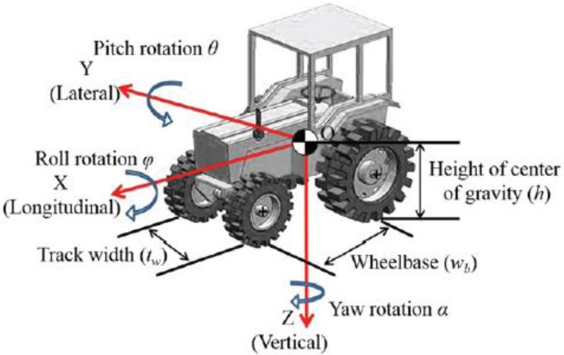
Tractor rigid model.
The actual status of off-road vehicles can be simplified into stationary form with dynamic actions considered, and tractor stability indices (SI) were developed for pitch and roll actions (Liu and Ayers, 1999). Equation 1 provides the dynamic stability indices including the effects of vehicle roll and pitch rotations:
| (1) |
where f and ? are the roll and pitch angles, φ is the roll rate, θ is the pitch rate, φcri is the critical roll rate, θcri is the critical pitch rate, and t is time. Equation 2 defines the critical pitch and roll angles, and equation 3 defines the critical pitch rate and critical roll rate:
| (2) |
| (3) |
where wb is the vehicle wheelbase, tw is the vehicle track width, h is the height of the vehicle center of gravity, m is the vehicle mass, g is acceleration due to gravity, and Jx and Jy are the moments of inertia for a solid cuboid along the x and y axes. The values of rx and ry can be determined using equation 4:
| (4) |
The centrifugal forces acting on a vehicle while it is turning affect the vehicle’s stability. Rollover may happen when a vehicle makes a sharp turn at a high speed or on slippery ground conditions. The dynamic stability indices including the effects of turning are given in equation 5:
| (5) |
where v is the vehicle speed while turning, calculated using equation 6, and vcri is the critical speed beyond which the vehicle will roll over, defined by equation 7:
| (6) |
| (7) |
where a is the lateral acceleration along the X axis, and R is the radius of the turn, which will be eliminated with the ratio of v/vcri as calculated. The overall stability index is calculated using equation 8:
| (8) |
This equation combines the effects of static stability, pitch and roll angles, pitch and roll rates, and vehicle turning speed into a single equation. The overall stability index ranges between 0 and 100, where 0 indicates a rollover condition, and 100 indicates the most stable operation of the vehicle.
iOS Application to Detect Rollover Accidents
The popularity of smartphones and similar portable electronic devices is increasing rapidly. These devices usually have a complete operating system and are equipped with several sensors, including accelerometer, gyroscope, magnetic, and GPS. Smartphones have also received considerable attention from researchers for the development of portable sensing platforms because of their hardware and software capabilities. Tacconi et al. (2011) developed a human falls and mobility detection system using smartphones to monitor elderly people. Lee and Chung (2012) proposed a smartphone-based method to measure vehicle safety-related data and monitor driver safety level. This research demonstrated the ability of smartphones for sensor data fusion, model implementation, and portability. Several researchers have applied smartphones in education, geosciences, and medicine (Joundi et al., 2011; Koc and Liu, 2013b; Takeuchi and Kennelly, 2010).
The tractor stability model mentioned earlier was implemented in a smartphone application to detect rollovers and transmit emergency notifications in case of an accident. The developed application has two modes: mode 1 is the iOS application that was developed for iPhones and iPads, and mode 2 is the backup system. In mode 1 operation, the smartphone has to be firmly mounted on the tractor. In this mode, the internal sensors of the smartphone are used to monitor the roll and pitch angles, their rates, and vehicle speed. The data from the internal sensors are processed by the phone, and the status of the operation is displayed on the phone’s screen. The display screen shows the roll and pitch angles and the overall stability index during tractor operation. Mode 2 requires mounting a backup system that contains an accelerometer, gyroscope, and GPS sensor on the tractor. In this mode, the data from the sensors are transmitted to a smartphone or a mobile device via Bluetooth. In mode 2, the smartphone or mobile device does not have to be mounted on the tractor. Based on the received sensor data, the mobile device computes the stability index. Schematic diagrams of the rollover detection and emergency notification system are shown in figures 2 and 3.
Figure 2.
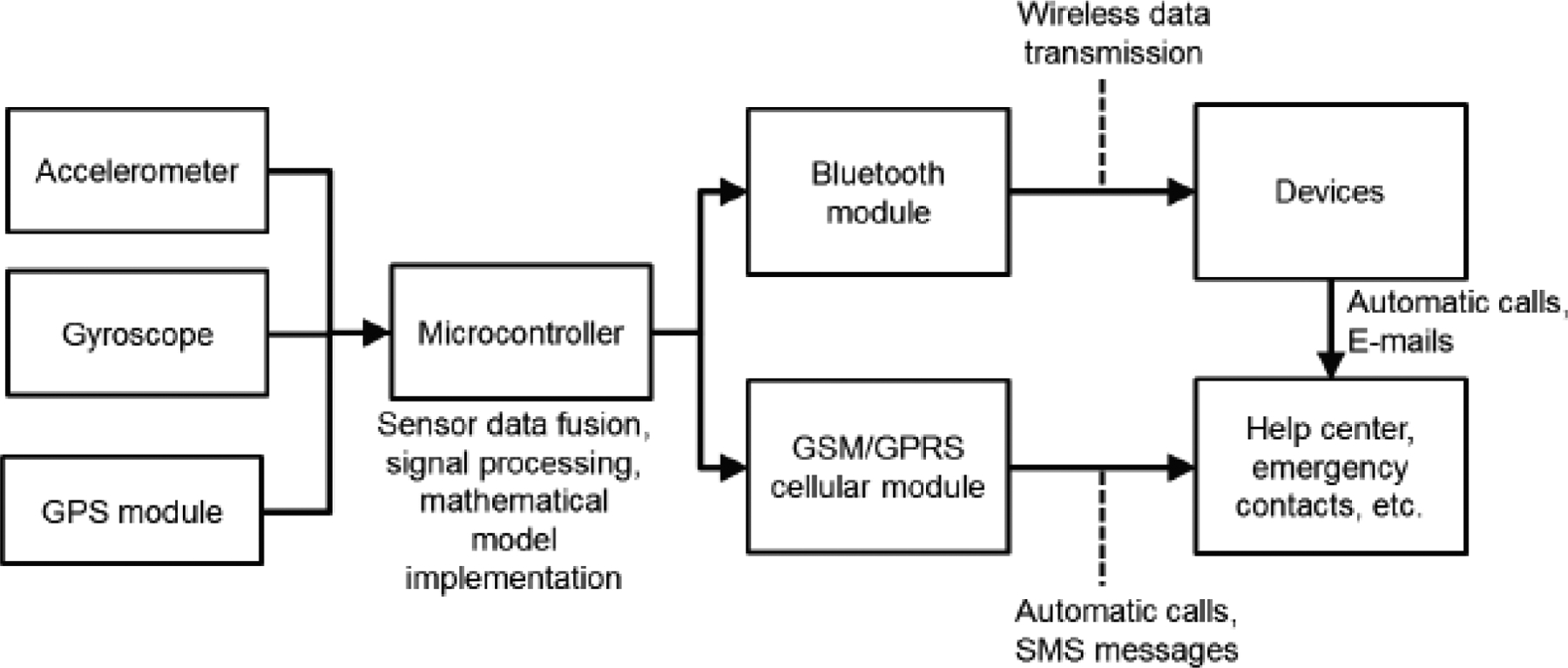
Schematic of backup system
Figure 3.
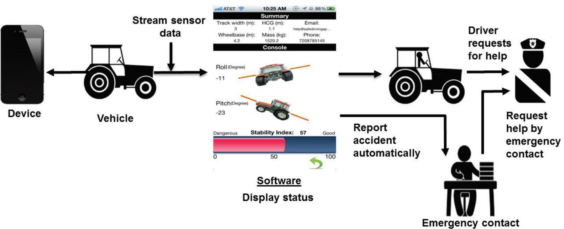
Schematic of rollover detection and emergency notification system
One of the challenges of integrating the tractor stability model into the rollover detection and emergency notification system is the determination of the roll and pitch angles. Other parameters can be measured directly from the accelerometer and gyroscope sensors with simple signal processing techniques or calculated directly from the tractor’s physical parameters. The accelerometer can be used to measure the projected gravity vector on the sensing axes. Hence, the accelerometer measures the pitch angle (?) and roll angle (f) between the sensitive axis Ax and X or between the sensitive axis Ay and Y, as shown in figure 4. The roll angle (f) and pitch angle (?) can be calculated using equation 10 and fit into the model with equation 9:
| (9) |
where Ax, Ay, and Az are the projected gravity components along the X, Y, and Z axes, and acc denotes the accelerometer. It is obvious that this technique will not be accurate when the accelerometer is subject to vibrations and noise signals.
Figure 4.
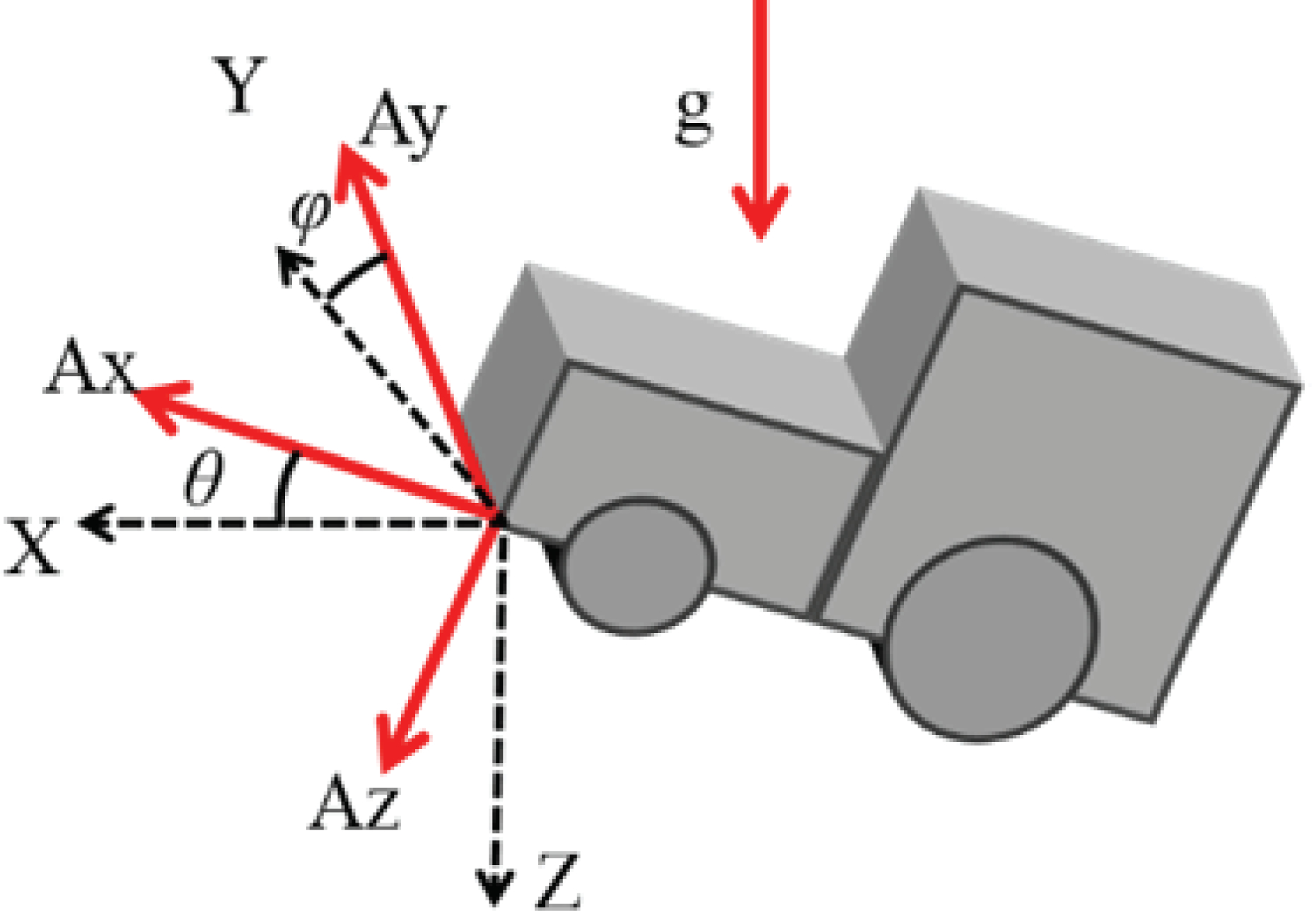
Determination of roll and pitch angles using an accelerometer
A gyroscope sensor is also used in smartphones to calculate angles. The gyroscope sensor can measure the angular rates around three axes. In order to measure the rotation angle, integrations of the signals from the gyroscope axes over time are needed (eq. 10):
| (10) |
where ω is the angular rate, Δt is the sampling interval of the sensor, and gyro denotes the gyroscope. One of the problems with this method is that the noise from data processing and from the measurements will be integrated when the data from the gyroscope sensor are integrated (Park et al., 2008). The high-frequency response of the gyroscope is reliable, but its low-frequency response is poor due to drift. On the other hand, the accelerometer response is drift-free, but it usually contains high-frequency vibration signals. After studying the characteristics of the gyroscope and accelerometer sensors, it becomes obvious that they each have their own strengths and weaknesses. In other words, the accelerometer and gyroscope sensors have characteristics that can be combined by using filtering techniques to improve their accuracies (Brown and Hwang, 1992).
A complementary filter with a data fusion technique was used to combine the contrary characteristics of the accelerometer and gyroscope to improve their accuracies (Brown and Hwang, 1992; Pascoal et al., 2000; Reif et al., 1999). In this study, acceleration and angular rate were the data inputs from the accelerometer and gyroscope, respectively. The accelerometer provided information with high-frequency noise and was filtered using a low-pass filter. The gyroscope input provided information with low-frequency noise and was filtered using a high-pass filter. During the entire process, the signals were subject to either the low-pass or high-pass filter, as shown in figure 5. Roll and pitch angles were calculated by combining the accelerometer and gyroscope data, as shown in equation 11:
| (11) |
where ß is a parameter that needs to be determined from offline measurements. The time constant of the complementary filter is defined by equation 12 (Lipták, 2003):
| (12) |
When a motion is faster than the t time period, the angle calculation based on gyroscope integration weighs more, and the accelerometer noise is filtered out. When a motion is slower than the t time period, the accelerometer angle measurement has more weight than the gyroscope to reduce the impact of the gyroscope’s bias drift.
Figure 5.
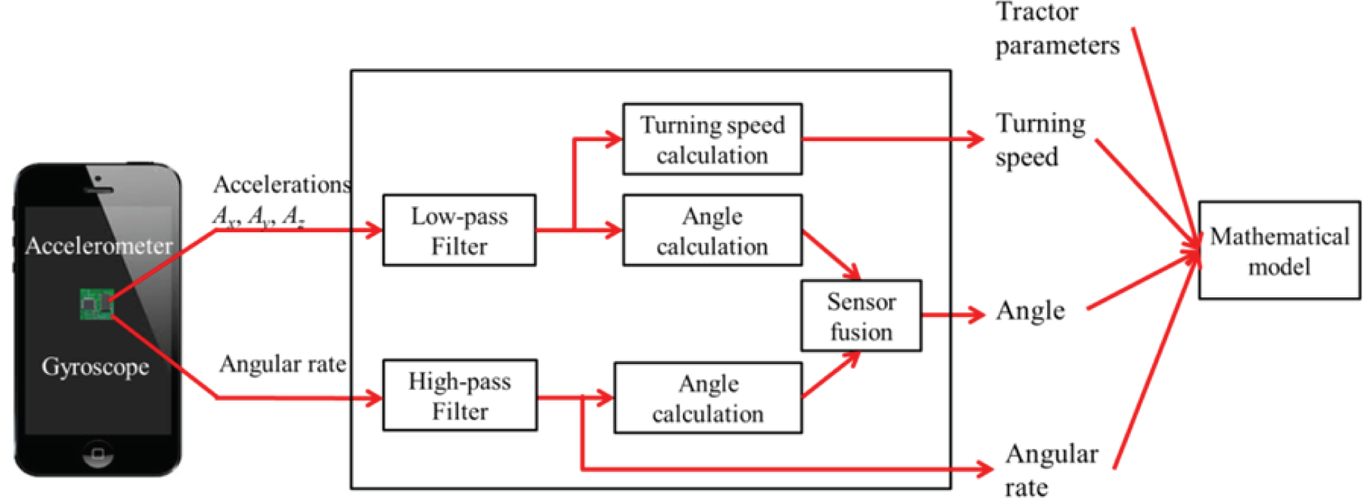
Implementation of complementary filter.
The mobile phone angles (the same as the vehicle angles) are calculated using the method shown in equations 10, 11, and 12. When the roll and pitch angles are determined based on the accelerometer data, engine vibration creates noise and causes instabilities. On the other hand, pitch and roll angles calculated from the gyroscope data have drift that increases over time due to the accumulated errors. However, the angles estimated with the complementary filter are fairly stable because the complementary filter takes advantage of both the accelerometer and gyroscope data, and this filter is not sensitive to gyroscope drift and accelerometer noise (Baerveldt and Klang, 1997).
An iOS application was created using iOS XCode (Apple, Inc., Cupertino, Cal.). This application uses the tractor physical parameters, which are required by the mathematical model as user inputs, and the processed sensor data to estimate the tractor stability index in real-time. The application displays a visual feedback message on the phone screen when a high rollover potential exists. If the application detects an accident, it automatically makes a phone call and sends an email notification, with the tractor location shown on a map, to the emergency contacts that were configured in the application. Screenshots of the application are shown in figure 6. Figure 6a shows the user input screen for the tractor physical parameters and emergency contact information. The stability status of the tractor is displayed on the screen shown in figure 6b. The stability index indicates how stable the tractor is during its operation. If the stability index value is low, a warning message is displayed on the screen (fig. 6c). Because rollover accidents occur in a very short time, a visual feedback message may not be very useful for the operator. However, such a visual display would be useful for training and education about tractor safety.
Figure 6.
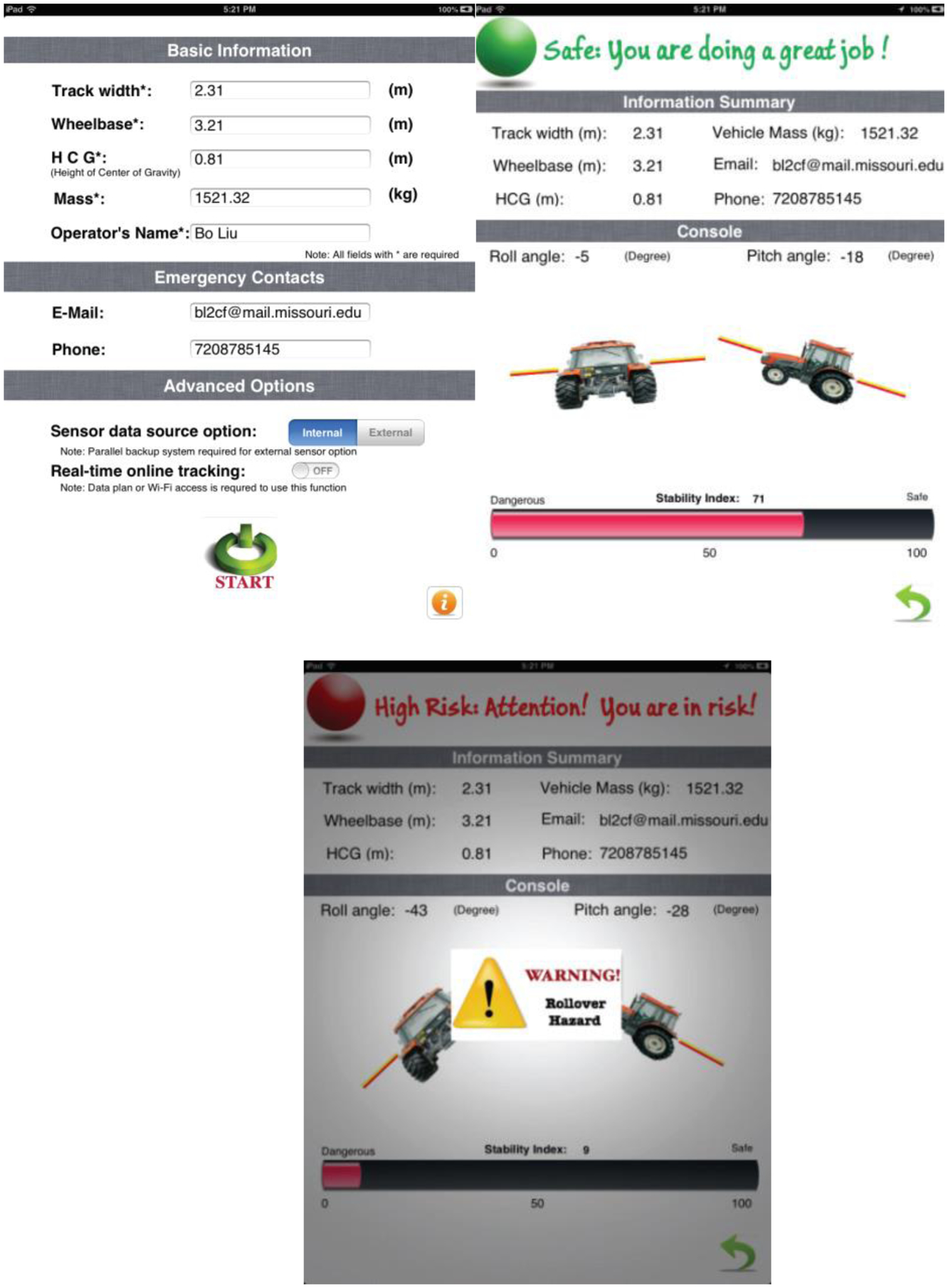
Application screenshots: (a) user input screen, (b) monitoring the vehicle stability index, and (c) feedback message when a rollover accident is about to happen.
Experimental Results
A John Deere 2040 2WD tractor was modified to be controlled remotely. The clutch, brakes, kill switch, and throttle were controlled with linear actuators via a 14-channel radio transceiver. The tractor ROPS was reinforced to prevent damage during rollover, and a metal frame was built around the hood to protect the engine components, as shown in figure 7. An iPhone 4S with the application installed was mounted on the frame above the hood. The track width, wheelbase, height of the center of gravity, and mass of the John Deere 2040 tractor were 1.6 m, 1.9 m, 0.6 m, and 2467.3 kg, respectively.
Figure 7.
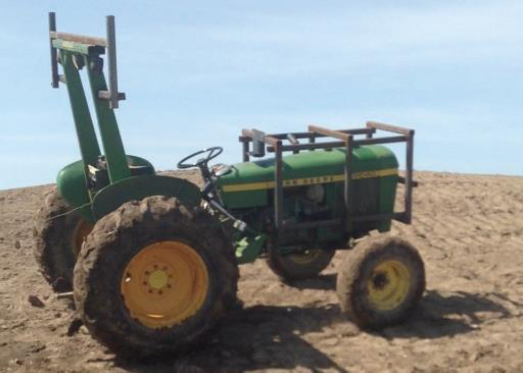
Modified remote-controlled John Deere 2040 2WD tractor
A ramp was built at the University of Missouri Bradford Research and Education Center. The tractor was brought to the side of the ramp before each test, and the gearshift was set to provide 10.8 or 21.6 km h−1 speeds. After a rollover, the engine was shut off, and the tractor was returned to its wheels with the help of another tractor. Ten field tests were conducted at 10.8 and 21.6 km h−1. Data on roll angle, pitch angle, roll rate, pitch rate, and stability index values over time were recorded during the tests.
Figure 8 shows the changes in roll and pitch angles, roll and pitch rates, and stability index with time for the tests at 21.6 km h−1. The changes in the roll and pitch angles and rates for all ten field tests are shown in the Appendix. The experimental results showed that the roll and pitch angles increased with increasing slope, while the stability index decreased. As the stability index approached zero (i.e., the tractor was about to roll over), the roll angle, pitch angle, roll rate, and pitch rate began to change dramatically. The iOS application displayed feedback messages on the screen when the stability index became lower than the threshold value of 20. This value is configurable for different users. The application also transmitted email messages to the emergency contacts and called the emergency contacts’ phone number when a rollover accident was detected (SI = 0) for all ten field tests.
Figure 8.
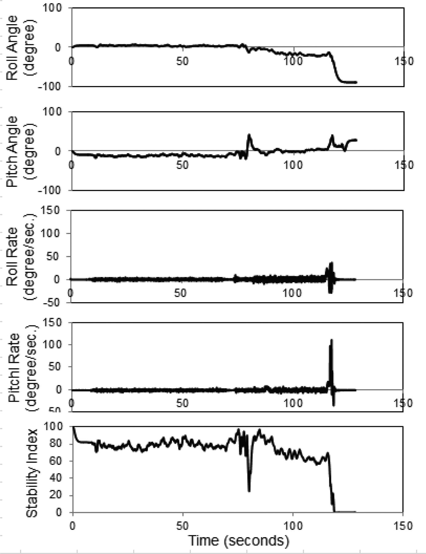
Roll angle, pitch angle, roll rate, pitch rate, and stability index for rollover tests at 21.6 km h−1.
The stability index model that was implemented in this research was a modified version of a model developed by Liu and Ayers (1999). While the modifications were made to detect rollovers due to centrifugal forces while turning, in addition to side and rear overturns, the model was tested for side rollovers in this study. For all of the side rollover tests on a field track, the rollover detection and emergency notification system successfully detected the accidents and transmitted the emergency notification messages. The accuracy and limitations of the modified stability index model need to be evaluated for rear overturns and for rollovers during turning with further field tests.
Conclusions
Tractor rollover tests were performed at 10.8 and 21.6 km h−1 to test the functions and reliability of a tractor rollover detection and emergency notification system developed for smartphones and mobile electronic devices. The system was able to monitor the stability of a tractor in real-time during its operation. The application successfully displayed graphical and numerical feedback messages to the operator. When the tractor rolled over, the application successfully transmitted an email message and made an emergency phone call automatically. The developed iOS application can be used as a teaching and education tool for demonstrating the safe operation of farm tractors. The time between the warning message and a rollover is often very short. Therefore, the developed system may not prevent an accident, but the application can transmit emergency messages and make automated phone calls when an accident is detected.
An emergency message with the GPS coordinates of the accident would reduce the emergency response time. A database or Quick Response (QR) code with tractor physical parameters would make the application more user-friendly. The rollover detection and emergency notification system can be modified for other vehicles, such as riding lawnmowers, construction and mining equipment, ATVs, and military vehicles. In addition, mechanical interventions to prevent rollover accidents could possibly be triggered with the developed system to control vehicles when a high rollover risk is detected.
Appendix: Tractor Rollover Field Test Results
Figure A1.
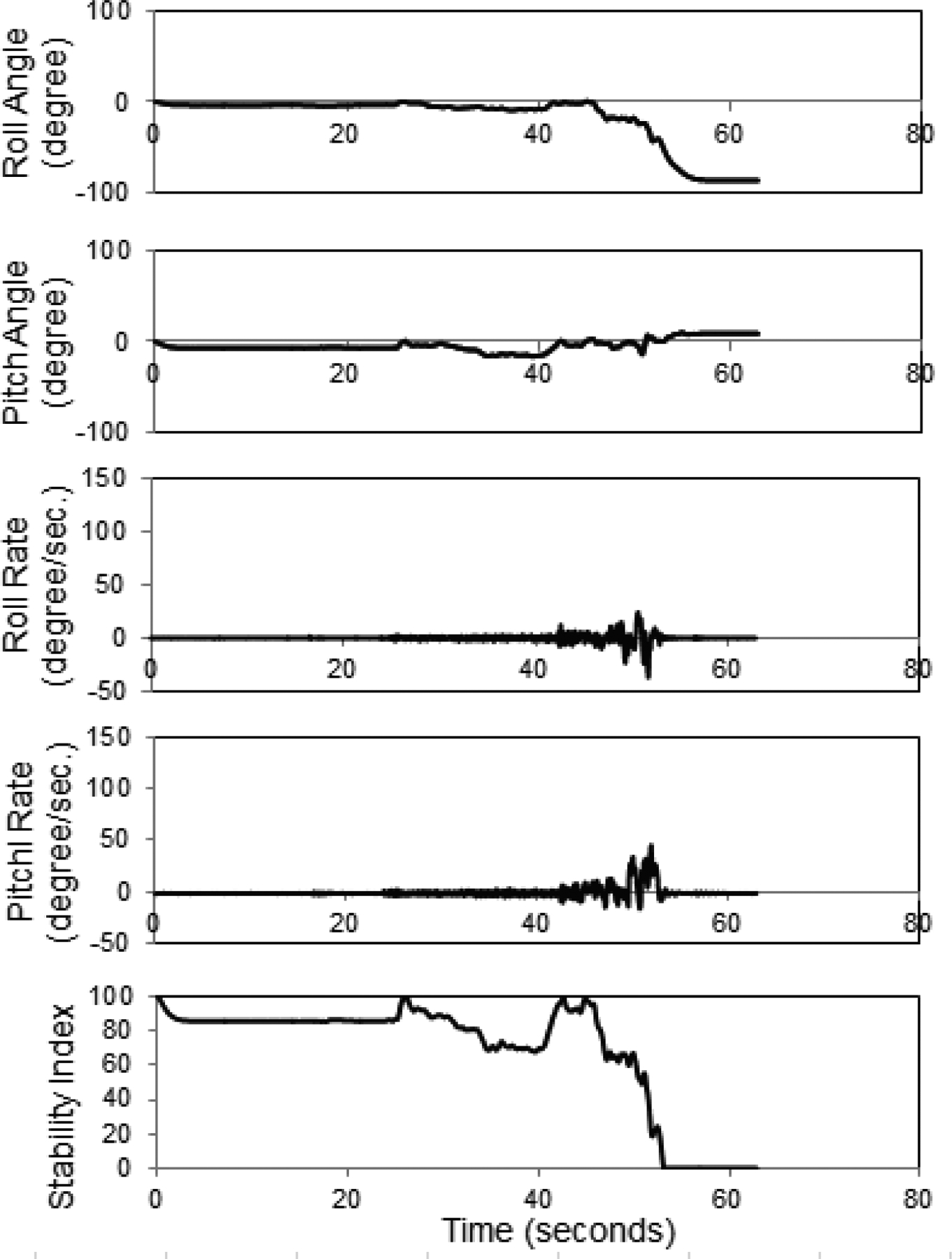
Trial at 10.8 km h−1
Figure A2.
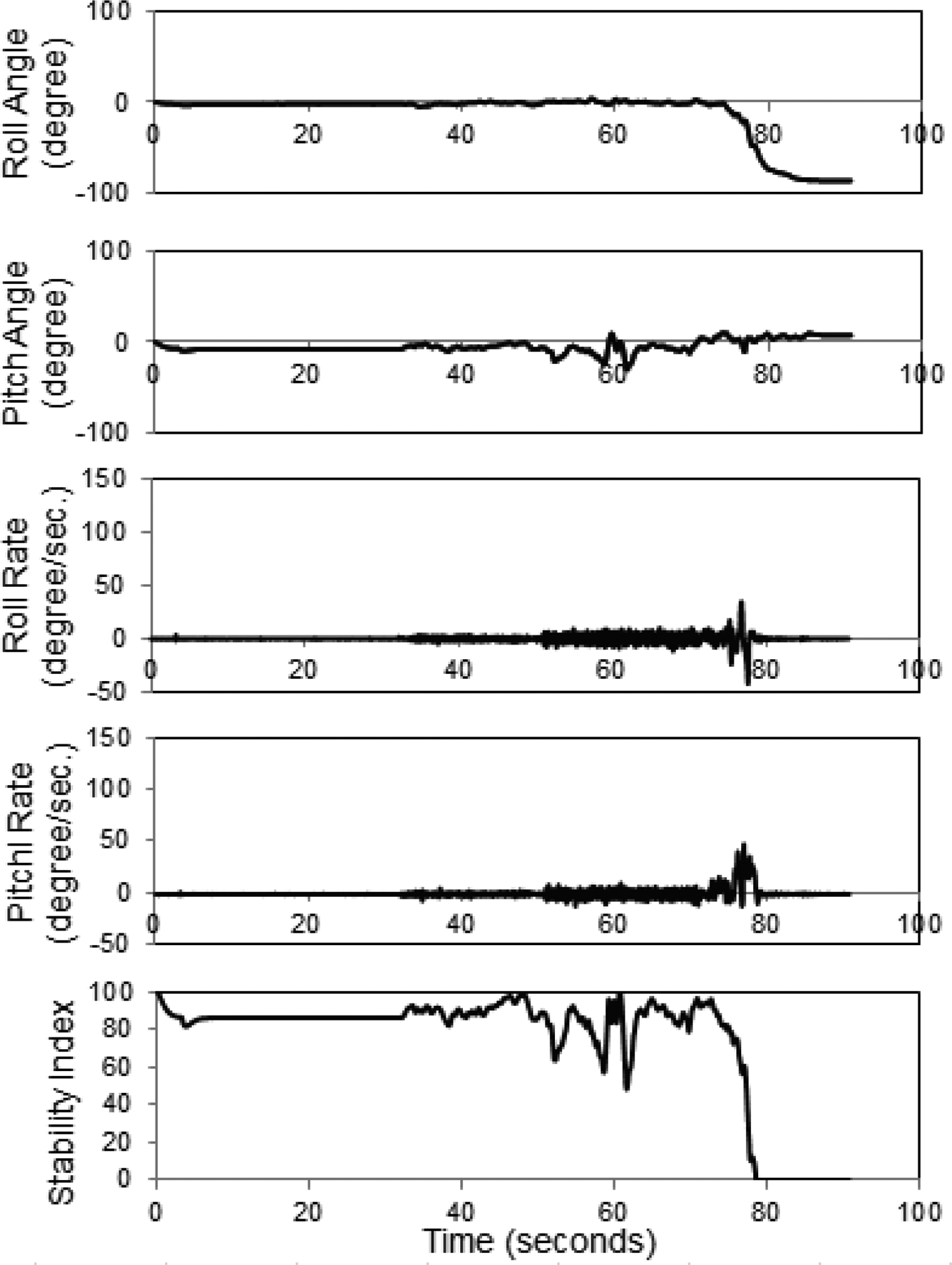
Trial 2 at 10.8 km h−1
Figure A3.
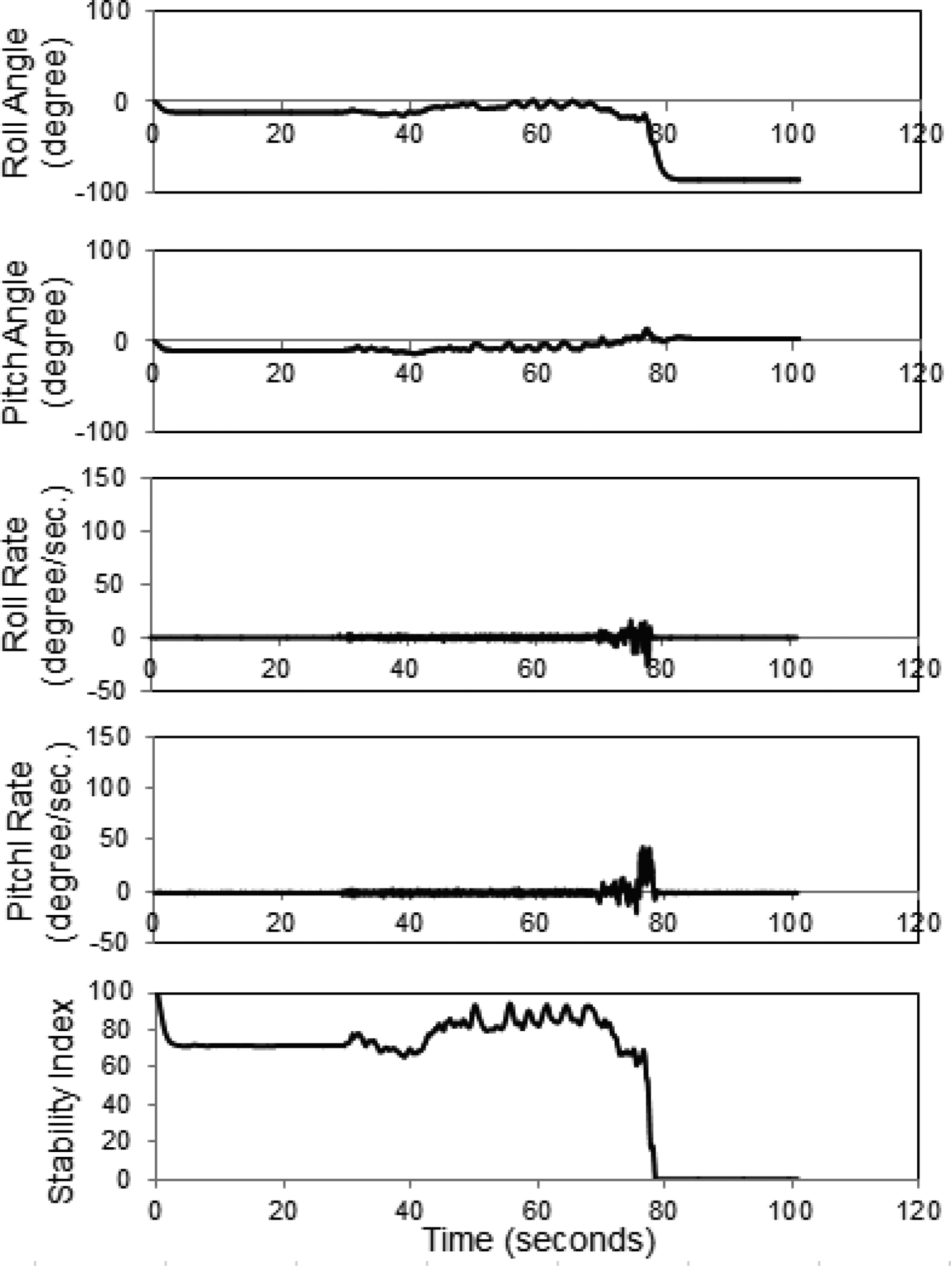
Trial 3 at 10.8 km h−1
Figure A4.
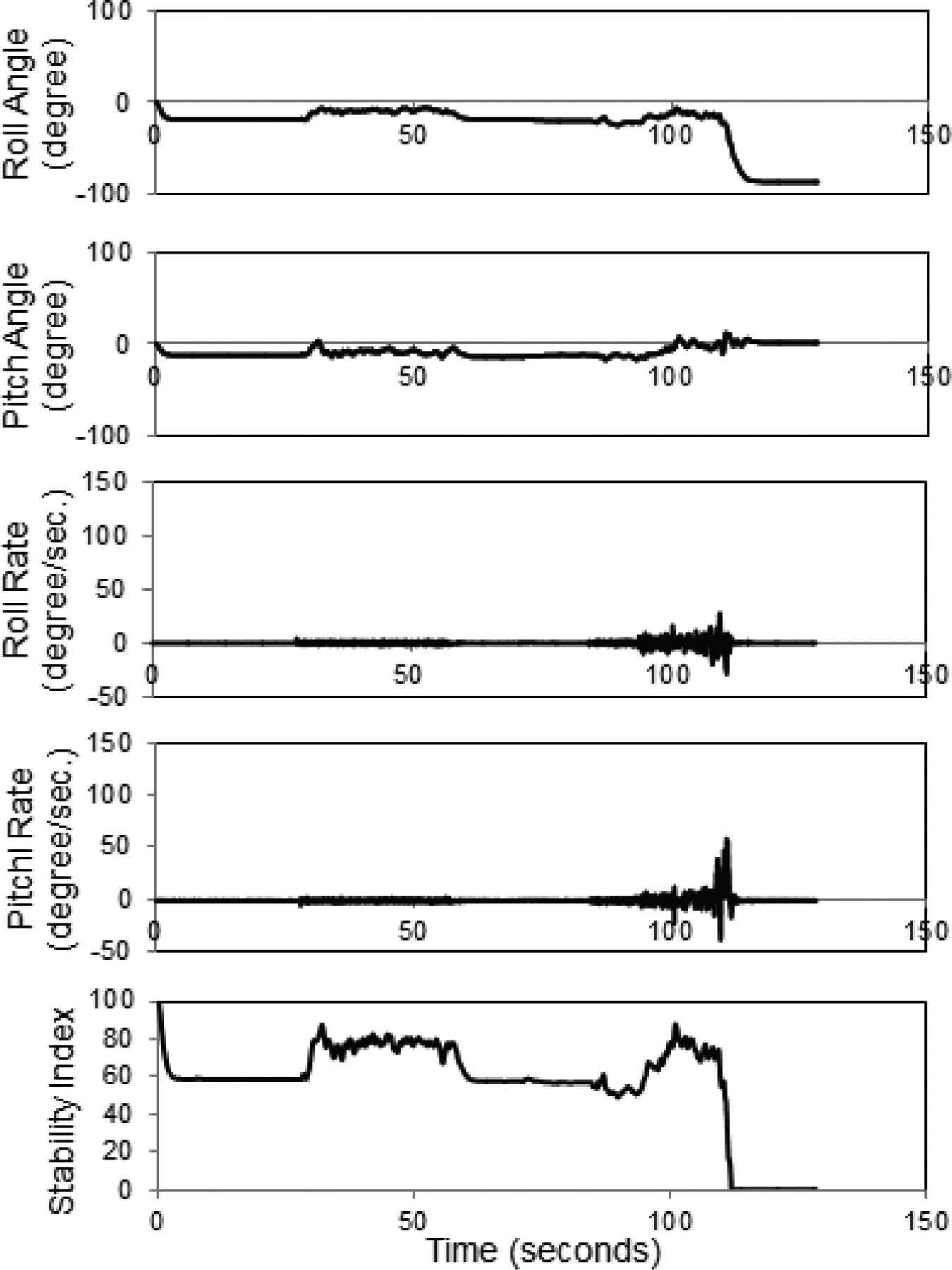
Trial 4 at 21.6 km h−1
Figure A5.
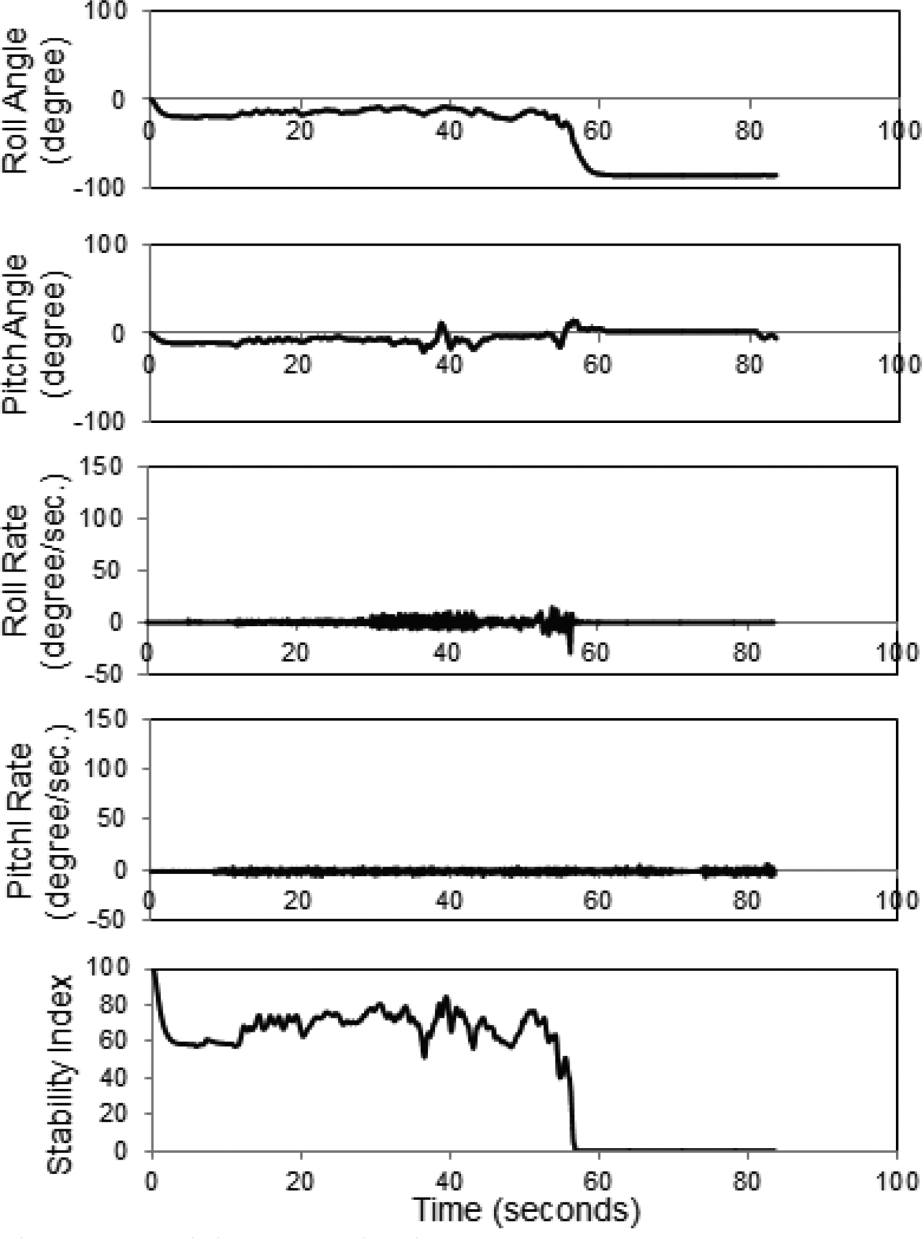
Trial 5 at 10.8 km h−1
Figure A6.
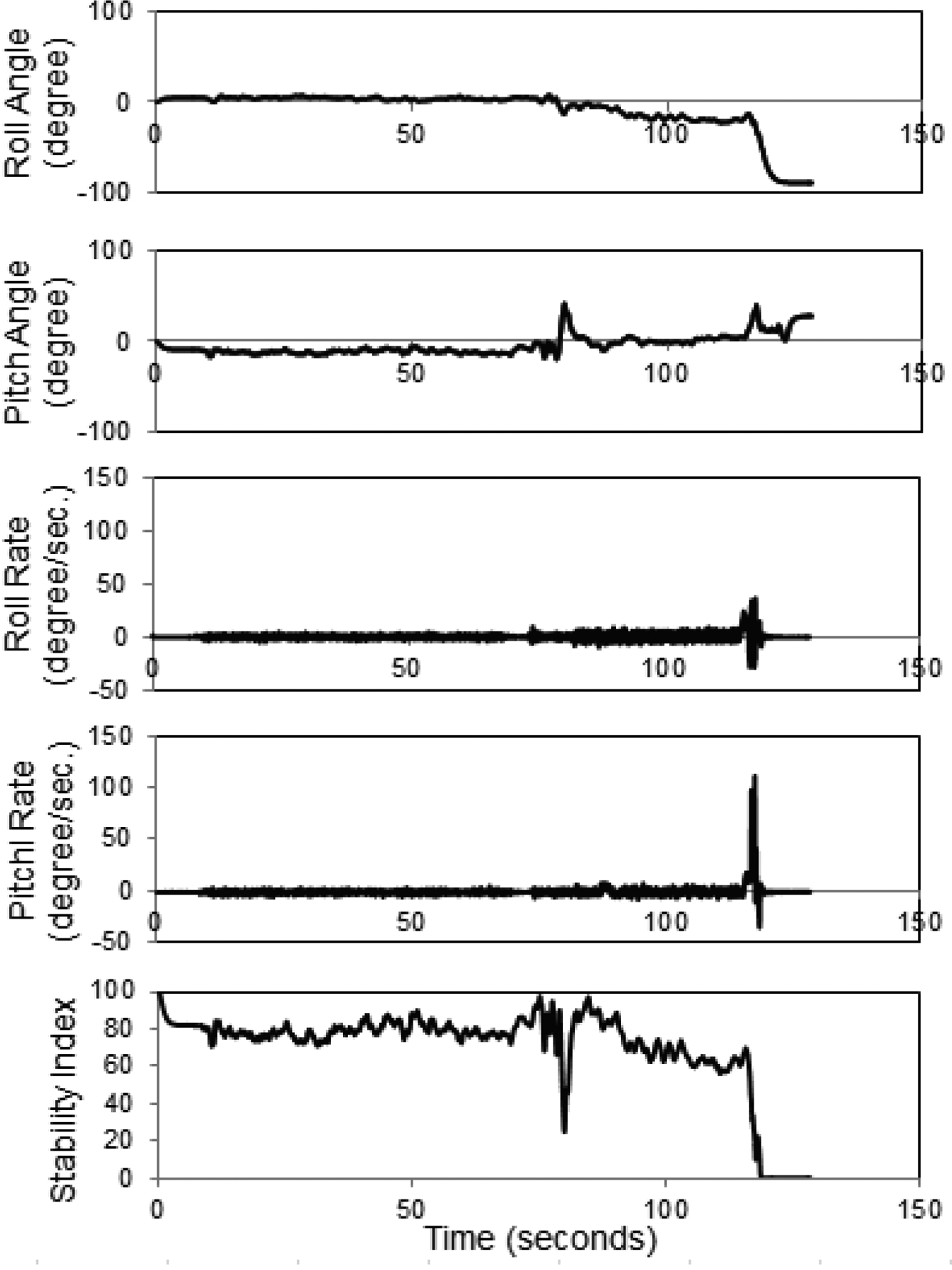
Trial 6 at 21.6 km h−1
Figure A7.
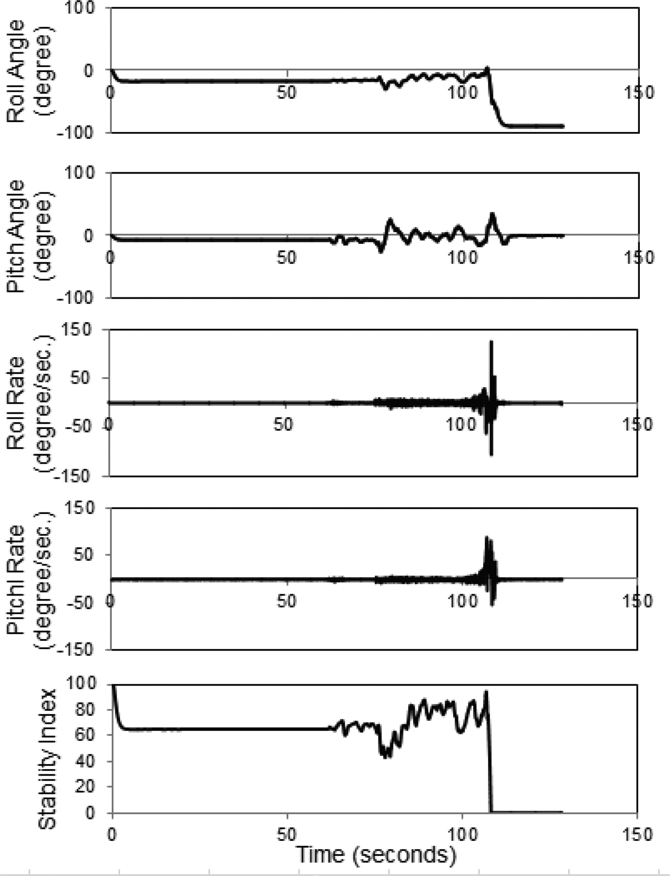
Trial 7 at 21.6 km h−1
Figure A8.
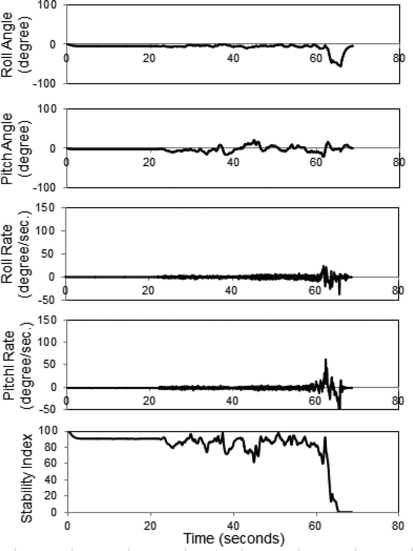
Trial 8 at 10.8 km h−1
Figure A9.
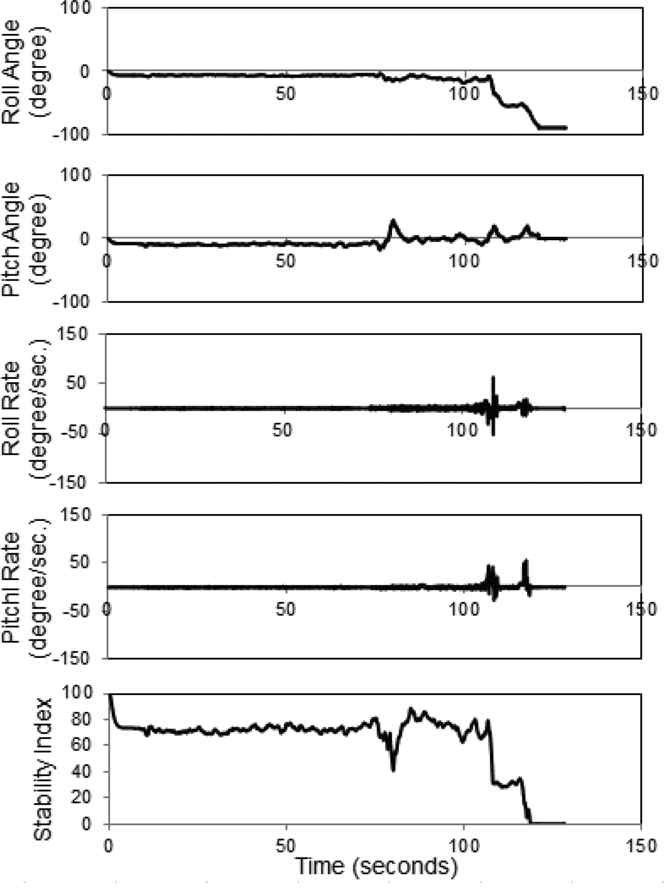
Trial 9 at 21.6 km h−1
Figure A10.
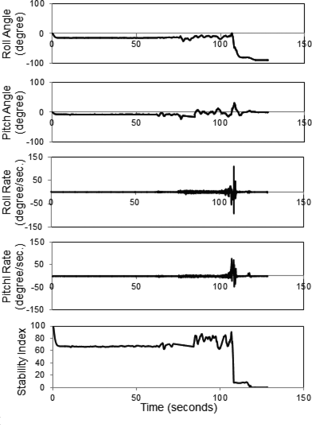
Trial 10 at 21.6 km h−1
References
- Baerveldt A-J, & Klang R (1997). A low-cost and low-weight attitude estimation system for an autonomous helicopter. In Proc. Intl. Conf. Intelligent Engineering Systems (INES ‘97) (pp. 391–395). Piscataway, N.J.: IEEE. [Google Scholar]
- Ballesteros T, Arana I, Pérez Ezcurdia A, & Alfaro JR (2013). E2D-ROPS: Development and tests of an automatically deployable, in height and width, front-mounted ROPS for narrow-track tractors. Biosystems Eng., 116(1), 1–14. [Google Scholar]
- Brown R, & Hwang P (1992). Introduction to Random Signals and Applied Kalman Filtering. New York, N.Y.: John Wiley and Sons. [Google Scholar]
- Eger R Kiencke U, (2003). Modeling of rollover sequences. Control Eng. Practice, 11(2), 209–216. [Google Scholar]
- Hyun D & Langari R (2003). Modeling to predict rollover threat of tractor-semitrailers. Vehicle System Dynamics, 39(6), 401–414. [Google Scholar]
- Joundi RA, Brittain J-S, Jenkinson N, Green AL, & Aziz T (2011). Rapid tremor frequency assessment with the iPhone accelerometer. Parkinsonism and Related Disorders, 17(4), 288–290. [DOI] [PubMed] [Google Scholar]
- Kim KU, & Rehkugler GE (1987). Review of tractor dynamics and stability. Trans. ASAE, 30(3), 615–623. [Google Scholar]
- Koc AB, & Liu B (2013a). Demonstrating tractor rollover stability using Lego Mindstorms and smart phones. J. Agric. Sys. Tech. Mgmt, 24, 1–11. [Google Scholar]
- Koc AB, & Liu B (2013b). Mobile app for tractor rollover detection and emergency notification. ASABE Paper No. 131620429. St. Joseph, Mich.: ASABE. [Google Scholar]
- Lee BG, & Chung WY (2012). A smartphone-based driver safety monitoring system using data fusion. Sensors (Switzerland), 12(12), 17536–17552. [DOI] [PMC free article] [PubMed] [Google Scholar]
- Lehtola CJ, Marley SJ, & Melvin SW (1994). Study of five years of tractor-related fatalities in Iowa. Appl. Eng. Agric, 10(5), 627–632. 10.13031/2013.25890. [DOI] [Google Scholar]
- Lipták BG (2003). Instrument Engineers’ Handbook: Process Control and Optimization (4th ed.). Boca Raton, Fla.: CRC Press. [Google Scholar]
- Liu J, & Ayers PD (1998). Application of a tractor stability index for protective structure deployment. J. Agric. Safety and Health (Special Issue), 171–181. [Google Scholar]
- Liu J, & Ayers PD (1999). Off-road vehicle rollover and field testing of stability index. J. Agric. Saf. Health, 5(1), 59–71. [Google Scholar]
- Liu B, & Koc AB (2013a). SafeDriving: A mobile application for tractor rollover detection and emergency reporting. Computers Electronics Agric., 98, 117–120. [Google Scholar]
- Liu B, & Koc AB (2013b). A vehicle rollover/accident prevention, education, training, and emergency reporting system. In Proc. 2013 ISASH Conf., Paper No. 13–06. International Society for Agricultural Safety and Health. [Google Scholar]
- Murphy DJ, Beppler DC, & Sommer HJ (1985). Tractor stability indicator. Appl. Ergonomics, 16(3), 187–191. [DOI] [PubMed] [Google Scholar]
- Murphy D, Myers J, McKenzie EA, Cavaletto R, May J, & Sorensen J (2010). Tractors and rollover protection in the United States. J. Agromed, 15(3), 249–263. [DOI] [PubMed] [Google Scholar]
- Nichol C, Sommer H 3rd, & Murphy D (2005). Simplified overturn stability monitoring of agricultural tractors. J. Agric. Safety and Health, 11(1), 99–108. [DOI] [PubMed] [Google Scholar]
- Park S, Horowitz R, & Tan C-W (2008). Dynamics and control of a MEMS angle measuring gyroscope. Sensors Actuators A, 144(1), 56–63. [Google Scholar]
- Pascoal A, Kaminer I, & Oliveira P (2000). Navigation system design using time-varying complementary filters. IEEE Trans. Aerospace Electronic, 36(4), 1099–1114. [Google Scholar]
- Pickett W, Hartling L, Brison RJ, & Guernsey JR (1999). Fatal work-related farm injuries in Canada. CMAJ, 160(13), 1843–1848. [PMC free article] [PubMed] [Google Scholar]
- Powers J, Harris J, Snyder K, Etherton J, Ronaghi M, & Newbraugh B (2001). Performance of a new ROPS on ASAE tests. J Agric. Safety and Health, 7(1), 51–61. [DOI] [PubMed] [Google Scholar]
- Reif K, Gunther S, Yaz E, & Unbehauen R (1999). Stochastic stability of the discrete-time extended Kalman filter. IEEE Trans. Automatic Control, 44(4), 714–728. [Google Scholar]
- Silleli H, Dayioglu MA, Gültekin A, Ekmekçi K, Yildiz MA, Akay E, & Saranli. (2007). Anchor mechanism to increase the operator clearance zone on narrow-track wheeled agricultural tractors: Prototype and first tests. Biosyst. Eng, 97(2), 153–161. [Google Scholar]
- Springfeldt B, Thorson J, & Lee BC (1998). Sweden’s thirty-year experience with tractor rollovers. J. Agric. Safety and Health, 4(3), 173–180. [Google Scholar]
- Tacconi C, Mellone S, & Chiari L (2011). Smartphone-based applications for investigating falls and mobility. In Proc. 5th Intl. Conf. on Pervasive Computing Technologies for Healthcare (pp. 258–261). Piscataway, N.J.: IEEE. [Google Scholar]
- Takeuchi K, & Kennelly PJ (2010). iSeismometer: A geoscientific iPhone application. Computers Geosci., 36(4), 573–575. [Google Scholar]


