eLife logoLink to eLife
. 2021 Mar 30;10:e64087. doi: 10.7554/eLife.64087

Structural determinants of voltage-gating properties in calcium channels

Monica L Fernández-Quintero 1,2,, Yousra El Ghaleb 1,, Petronel Tuluc 3, Marta Campiglio 1, Klaus R Liedl 2, Bernhard E Flucher 1,
Editors: Toby W Allen4, Richard W Aldrich5
PMCID: PMC8099428  PMID: 33783354

Abstract

Voltage-gated calcium channels control key functions of excitable cells, like synaptic transmission in neurons and the contraction of heart and skeletal muscles. To accomplish such diverse functions, different calcium channels activate at different voltages and with distinct kinetics. To identify the molecular mechanisms governing specific voltage sensing properties, we combined structure modeling, mutagenesis, and electrophysiology to analyze the structures, free energy, and transition kinetics of the activated and resting states of two functionally distinct voltage sensing domains (VSDs) of the eukaryotic calcium channel CaV1.1. Both VSDs displayed the typical features of the sliding helix model; however, they greatly differed in ion-pair formation of the outer gating charges. Specifically, stabilization of the activated state enhanced the voltage dependence of activation, while stabilization of resting states slowed the kinetics. This mechanism provides a mechanistic model explaining how specific ion-pair formation in separate VSDs can realize the characteristic gating properties of voltage-gated cation channels.

Research organism: Mouse

eLife digest

Communication in our body runs on electricity. Between the exterior and interior of every living cell, there is a difference in electrical charge, or voltage. Rapid changes in this so-called membrane potential activate vital biological processes, ranging from muscle contraction to communication between nerve cells.

Ion channels are cellular structures that maintain membrane potential and help ‘excitable’ cells like nerve and muscle cells produce electrical impulses. They are specialized proteins that form highly specific conduction pores in the cell surface. When open, these channels let charged particles (such as calcium ions) through, rapidly altering the electrical potential between the inside and outside the cell.

To ensure proper control over this process, most ion channels open in response to specific stimuli, which is known as ‘gating’. For example, voltage-gated calcium channels contain charge-sensing domains that change shape and allow the channel to open once the membrane potential reaches a certain threshold. These channels play important roles in many tissues and, when mutated, can cause severe brain or muscle disease.

Although the basic principle of voltage gating is well-known, the properties of individual voltage-gated calcium channels still vary. Different family members open at different voltage levels and at different speeds. Such fine-tuning is thought to be key to their diverse roles in various parts of the body, but the underlying mechanisms are still poorly understood. Here, Fernández-Quintero, El Ghaleb et al. set out to determine how this variation is achieved.

The first step was to create a dynamic computer simulation showing the detailed structure of a mammalian voltage-gated calcium channel, called CaV1.1. The simulation was then used to predict the movements of the voltage sensing regions while the channel opened.

The computer modelling experiments showed that although the voltage sensors looked superficially similar, they acted differently. The first of the four voltage sensors of the studied calcium channel controlled opening speed. This was driven by shifts in its configuration that caused oppositely charged parts of the protein to sequentially form and break molecular bonds; a process that takes time. In contrast, the fourth sensor, which set the voltage threshold at which the channel opened, did not form these sequential bonds and accordingly reacted fast. Experimental tests in muscle cells that had been engineered to produce channels with mutations in the sensors, confirmed these results.

These findings shed new light on the molecular mechanisms that shape the activity of voltage-gated calcium channels. This knowledge will help us understand better how ion channels work, both in healthy tissue and in human disease.

Introduction

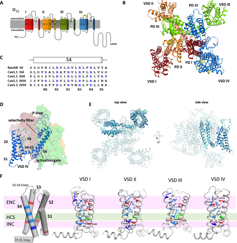
Voltage-gated calcium channels (CaV) translate membrane depolarization into calcium influx. Thus, they contribute to cellular excitability and they couple electrical activity to fundamental cell functions like contraction of heart and skeletal muscle, secretion of neurotransmitters and hormones, and the regulation of gene expression. Together with voltage-gated sodium channels (NaV), CaVs form a structurally related ion channel superfamily with a fourfold symmetry (Figure 1A). Their pore-forming α1 subunits are composed of four homologous but non-identical domains (repeats I-IV), each containing six transmembrane helices (S1-S6). The S5 and S6 helices plus the connecting P loop of all four repeats form the central channel pore with the selectivity filter and the activation gate (Catterall et al., 2020). Helices S1-S4 of each repeat form separate voltage sensing domains (VSDs). The S4 helix contains positively charged residues (termed gating charges) in every third position, and its movement across the electric field upon membrane depolarization is thought to initiate the conformational change resulting in channel opening (Catterall et al., 2017).

Figure 1. Structure model of the hetero-tetrameric human CaV1.1.

(A) Domain structure of eukaryotic CaV channels. (B) Structure model of the human CaV1.1 α1 subunit (top view; color code as in A) refined with molecular dynamics (MD) simulation in a membrane environment (see 'Materials and methods') based on the 3.6 Å structure of rabbit CaV1.1 (Pan et al., 2018; Wu et al., 2016). (C) Sequence alignment of the S4 helices of each CaV1.1 voltage sensing domain (VSD) compared to the homo-tetrameric NaVAb; gating charges (R, K) are indicated in blue. (D) Structure of a single repeat (IV) within the space-filling model of CaV1.1. (E) Structural overlay of NaVAb with VSD IV of CaV1.1. (F) Cylindrical representation of the VSD structure showing the positive gating charges in S4 (blue) and countercharges (red) of the intra- and extracellular negative clusters (INC, ENC) in S1, S2, and S3. The phenylalanine in S2, marking the hydrophobic constriction site (HCS), is indicated in green. Ribbon models of the four VSDs of CaV1.1 in the up-state, showing the side chains of the S4 gating charges (R, light blue; K, dark blue) and their putative ion-pair partners (red). Note that the numbers and positions of the ion-pair interactions in the ENC differ between the VSDs.

Figure 1.

Figure 1—figure supplement 1. Structure comparison of the four voltage sensing domains (VSDs) of CaV1.1 with the VSD of NaVAb.

Figure 1—figure supplement 1.

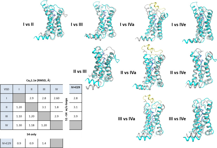
Comparison of the individual four VSDs of CaV1.1 with the VSD of NaVAb (Payandeh et al., 2011) illustrates the overall similarity with the ancestral channel. At the same time highlights the structural differences between the CaV1.1 VSDs. NaVAb, orange; CaV1.1 VSD are color-coded according to Figure 1A; exon 29 in the S3-S4 linker of VSD IVa is shown in yellow.

Figure 1—figure supplement 2. Structure comparison between the four voltage sensing domains (VSDs) of CaV1.1.

Figure 1—figure supplement 2.

Structural overlay of all four VSDs with each other to visualize the structural differences between each VSD. The first mentioned of each pair is shown in turquoise, the second in gray; exon 29 in the IVS3-S4 loop is shown in yellow. The root-mean-square deviation (RMSD) values calculated of the VSDs without loops indicate the similarities of VSD I with VSD III, and of VSD II with VSD IV. Insertion of exon 29 in VSD IVa decreases its structural similarity with the other VSDs.

Several high-resolution structures of prokaryotic and eukaryotic NaV channels have been solved (Lenaeus et al., 2017; Pan et al., 2018; Payandeh et al., 2011; Yan et al., 2017; Zhang et al., 2012). Recent advances in cryo-electron microscopy (cryo-EM) enabled the determination of the structure of the voltage-gated calcium channel CaV1.1 at 3.6 Å resolution, displaying a closed pore and the VSDs in the activated up-state (Wu et al., 2016; Wu et al., 2015). Very recently, three cryo-EM structures of homo-tetrameric sodium channels experimentally locked in resting (or VSD-down) states have been reported (Wisedchaisri et al., 2021; Wisedchaisri et al., 2019; Xu et al., 2019). However, up to now the resting states of eukaryotic CaV and NaV channels remained inaccessible to experimental structure determination. Nevertheless, many years of experimental work and structure modeling provide ample support for the sliding helix model of the voltage sensor action (Catterall et al., 2017; Yarov-Yarovoy et al., 2012). According to this model, the negative membrane potential at rest pulls the positively charged S4 helices down toward the cytoplasmic side of the membrane holding the channel gate closed. The reversal of the electric field upon membrane depolarization causes the outward displacement of the S4 helix by about 10 Å. The movement of two to three positive gating charges through the hydrophobic constriction site (HCS) in the center of the VSD is facilitated by the transient formation of ion-pair interactions with negative countercharges in the other helices of the VSD (Catterall et al., 2017).

While this model describes the principal mode of voltage sensor action, without further structure-function data, it does not explain how the four homologous but structurally distinct VSDs of eukaryotic channels cooperate in channel gating and how the unique gating properties of different channel isoforms are achieved. The distinct structure of the four VSDs of eukaryotic NaV and CaV suggests that there might be considerable variability between the four VSDs of a channel in the movement of the S4 helices and the molecular interactions of their gating charges. In fact, accumulating evidence indicates functional differences between the VSDs of individual channel isoforms (Ahern et al., 2016; Pantazis et al., 2014; Tuluc et al., 2016a). The rabbit skeletal muscle CaV1.1 is the first member of the CaV family for which the structure has been solved (Wu et al., 2016; Wu et al., 2015; Zhao et al., 2019). Biophysically it is characterized by slow kinetics and right-shifted voltage dependence of activation (Tuluc et al., 2016a). Together these attributes make CaV1.1 a prime candidate for studying how specific structural features of the VSDs determine voltage dependence and kinetics of channel activation.

Here, we applied molecular dynamics (MD) simulation and Markov state modeling (MSM) combined with site-directed mutagenesis and electrophysiological analyses to identify the molecular mechanism by which individual VSDs determine the characteristic voltage dependence and kinetics of current activation. Our structure models of the activated and resting states of CaV1.1 VSDs I and IV are consistent with the sliding helix model and yielded reliable predictions of the importance of ion-pair formation between the outer gating charges and various countercharges within the particular VSD. Our data provide novel insight in how the stabilization of the VSDs in resting and/or the activated states shapes the kinetics and voltage dependence of activation, respectively.

Results

The structure of CaV1.1 reveals differences between VSDs

Based on the cryo-EM structure of CaV1.1 (Wu et al., 2016; Wu et al., 2015), we generated a new structural model to study the molecular mechanisms determining the specific gating properties of this voltage-gated calcium channel. To this end, we used the Rosetta computational modeling software (Bender et al., 2016; Rohl et al., 2004) to build a homology model of the human eukaryotic CaV1.1 and included all missing loops and modeled both splice variants with and without exon 29 (Tuluc et al., 2009). The resulting models were equilibrated and simulated at 300 K in the membrane environment to identify favorable side-chain orientations and to relax the protein.

CaV1.1 is a pseudo-tetrameric channel with a domain-swapped arrangement in which each VSD (S1-S4) is positioned next to the pore domain (S5-S6) of the adjacent repeat in a clockwise orientation (Catterall et al., 2017Figure 1B,D). The structures of the individual repeats closely resemble the crystal structure of NaVAb (Cα root-mean-square deviation [RMSD] of 2.7 Å) (Payandeh et al., 2011), which is regarded as phylogenetic ancestor of CaV and NaV channels and for which considerable structural information is available (Figure 1E; Figure 1—figure supplement 1). While all four VSDs of CaV1.1 display the canonical voltage sensor fold, individually they differ from one another in significant aspects like the length of the helical structures and the number of gating charges in S4 (Figure 1—figure supplement 2). Only VSD IV contains four gating charges (R1-R4) at the three-residue interval, like NaVAb (Figure 1C). VSDs I and III possess an additional positive charge (K0) at the outer end of S4, and VSD II an additional gating charge (K5) at the cytoplasmic side of S4. All four VSDs are in the activated (S4-up) state in that (K0) R1, R2, and R3 are positioned above the phenylalanine (in S2) of the HCS and R4 (and K5) below (Figure 1F).

As predicted by the sliding helix model (Catterall et al., 2017), the gating charges form ion pairs with countercharges of the extracellular negative cluster (ENC) and intracellular negative cluster (INC). The interactions of the inner gating charges with countercharges of the INC are identical in the four VSDs of CaV1.1, representing the typical arrangement of the highly conserved charge transfer center (Tao et al., 2010). However, between the VSDs, the outer ion-pair interactions differ. Overall, the four VSDs of CaV1.1 can be grouped into two classes – VSDs I and III, and VSDs II and IV, respectively – each with the same number and position of countercharges in the ENC. While in VSDs I and III, the gating charges form ion pairs with two glutamate residues in the S2 helix, VSDs II and IV gating charges interact with one negative countercharge each in the S2 and S3 helices. Also, in VSDs I and III, the additional outermost gating charges are lysines (K0), whereas in VSDs II and IV, the innermost gating charge is a lysine residue (K4) instead of an arginine (R4) in VSDs I and III. Note that lysine forms only a single interaction with a negative countercharge in the INC as opposed to two formed by arginine. Together these differences in the ion pairs formed by the gating charges indicate that the activated state of VSDs I and III is considerably more stabilized than that of VSDs II and IV.

MD simulation and MSM of VSD I in activated and resting states

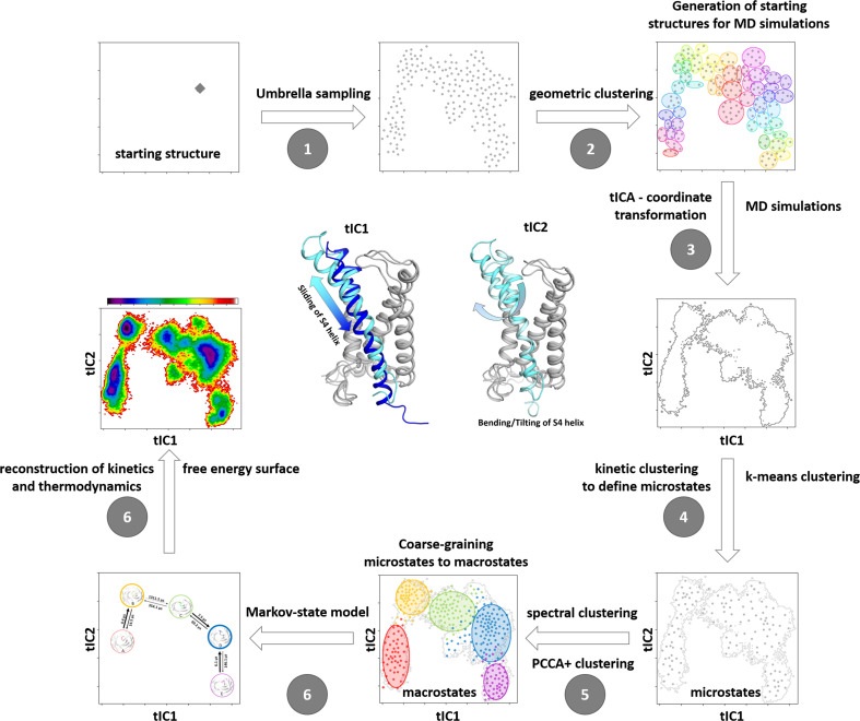
The interactions between gating charges and their ion-pair partners observed in the structure model based on available cryo-EM structures of CaV1.1 merely represent a snapshot depicting the endpoint of the voltage sensing process. However, because high-resolution structures of resting states of CaV channels are lacking, the molecular details of the steps leading up to VSD activation are still elusive. Exploiting the potential of structure modeling to fill this gap (Jensen et al., 2012; Yarov-Yarovoy et al., 2012), we applied MD simulation and MSM of individual VSDs to predict the structures, kinetics, and energy levels of resting states. To overcome the high energy barriers and the timescale limitations of MD simulations in the absence of the membrane potential, we used Umbrella sampling. This enhanced sampling technique explores the conformational transitions of a VSD as the positively charged S4 helix moves along the likely pathway toward the cytoplasmic side of the VSD, and thus create the seeding points for subsequent MD simulations. For this purpose, the obtained structures were clustered based on a geometrical RMSD criterion resulting in about 50 cluster representatives. These were simulated for 100 ns each (aggregated simulation time close to 5 µs) to obtain unbiased trajectories, which were then projected in a time-lagged independent component analysis (tICA), representing the slowest reaction coordinates. Finally, the kinetic coordinate system provided by the tICA allows calculation of thermodynamics and kinetics by an MSM (Figure 2—figure supplement 1).

Using this approach, we modeled the resting state structures of CaV1.1 VSDs I and IV, because they represent the two structurally distinguishable classes of VSDs (see Figure 1F; Figure 1—figure supplement 2), and because they differentially regulate the specific gating properties of skeletal muscle calcium currents. VSD I determines CaV1.1’s slow activation kinetics and VSD IV its voltage-dependence of activation (Nakai et al., 1994; Tuluc et al., 2016a). The latter is regulated by alternative splicing in that exclusion of the 19 amino acids of exon 29 from the extracellular loop linking IVS3 and IVS4 causes a 30 mV left-shift of the voltage dependence of activation and a several-fold increase in current density (Tuluc et al., 2009). Previously we demonstrated that the loss of voltage sensitivity upon insertion of exon 29 is caused by the relative lateral displacement of S3 and S4 and the resulting loss of ionic interactions of the outer gating charges (R1, R2) with a single countercharge (D1196) in the S3 helix (Tuluc et al., 2016b). Considering the importance of these ionic interactions in VSD IV for regulating the channel’s voltage dependence, we hypothesized that similarly the specific kinetic properties of CaV1.1 may be encoded in the structure, ionic interactions, and the molecular kinetics of the state transitions of VSD I.

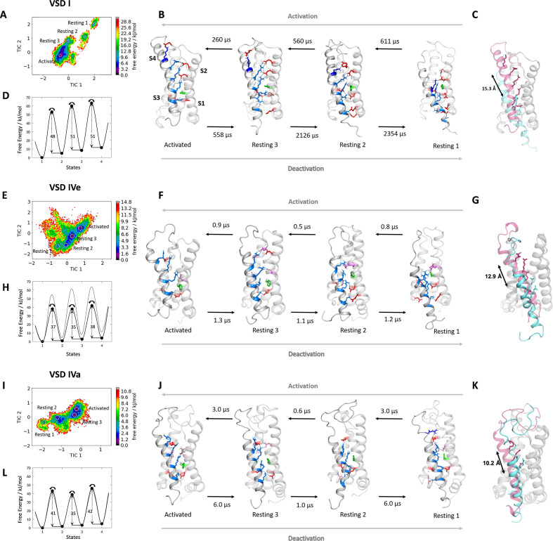
The free energy maps calculated for the MD simulation of VSD I, VSD IVe, and VSD IVa each comprised four energy minima (Figure 2A,E,I) and the corresponding structures resembled the activated and three resting states, as predicted by the sliding helix model. Across these states, the S4 helix of VSD I described a stepwise downward movement of 15.3 Å, corresponding to three helical turns (Figure 2B,C). In the activated state, the gating charges K0, R1, R2, and R3 were above phenylalanine (F97) of the HCS, and only R4 was below it. In the deepest resting state 1, only K0 and R1 were positioned above the HCS, while R2, R3, and R4 were located below it. In all four states, IS4 adopted a shifting stretch of 310 helical conformation (Figure 2—figure supplement 2), so that the side chains of the gating charges all pointed toward the center of the VSD. As IS4 moved from the activated state to resting state 1, R4, R3, R2, and R1 sequentially formed ion pairs with countercharges of the INC (E100 in IS2 and D126 in IS3), which are part of the highly conserved charge transfer center of voltage-gated cation channels (Figure 2B; Figure 3ATao et al., 2010). In all states also the gating charges above and below the HCS formed extensive ionic bonds with negative countercharges in IS1 and IS2. In the resting states 2 and 3 and in the activated state R1, R2, and R3 formed ion bonds with E87 and E90, plus in resting state 3 and the activated state K0 formed an additional ion bond with E76 in the IS1-S2 loop. In resting states 1 and 2, gating charges R3 and R4 formed ion bonds with E49 and E54 at the cytoplasmic end of IS1. This multitude of ionic interactions stabilizes each of the consecutive states and thus strictly delineates the path of IS4 through VSD I upon channel activation and deactivation. Note that in addition to the indicated ionic bonds, the gating charges form transient hydrogen bonds and hydrophobic and polar interactions with several other putative interaction partners, all of which might contribute to the movement of S4 across the membrane electrical field, but are not subject of the present study.

Figure 2. Molecular dynamics (MD) simulation and kinetics of voltage sensor transitions of voltage sensing domains (VSDs) I and IV with and without exon 29.

(A,E,I) The free energy surfaces of 5.0 µs trajectories of VSD I (A), VSD IV of CaV1.1e (E), and CaV1.1a including exon 29 (I) reconstructed in the time-lagged independent component analysis (tICA) coordinate space resulted in four macrostates. (B,F,J) Representative structures of each VSD in the four macrostates correspond to three resting and the activated states. The S4 gating charges (blue) show a sequential movement relative to the phenylalanine (green) in the hydrophobic constriction site (HCS) and stabilizing interactions with ion-pair partners (red) and H-bond donors/acceptors (pink) in the intracellular negative cluster (INC) and extracellular negative cluster (ENC). Transition kinetics (in µs) were calculated using a Markov state model. (C,G,K) Overlays of the activated (magenta) and resting state 1 (cyan) illustrating the maximum displacement of S4 during activation. (D,H,L) Schematic 1D representations of the free energy surface of VSD I (D), VSD IV of CaV1.1e (H), and CaV1.1a (L), with energy barriers calculated using transition state theory at 0 mV favoring the activated state. Gray trace in (H) shows free energy surface of (D) for comparison; gray trace in (L) shows free energy surface of (H) for comparison. Because in skeletal muscle cells, VSDs II and III probably control excitation-contraction coupling (Flucher, 2020; Flucher, 2016), and as their contribution to channel gating is less well understood, we did not include them in the present study.

Figure 2.

Figure 2—figure supplement 1. Schematic illustration of our robust protocol for describing and characterizing protein dynamics and statistically validating the results by constructing a Markov state model (MSM).

Figure 2—figure supplement 1.

(1) We applied Umbrella sampling as enhanced sampling technique to overcome the timescale limitations of classical molecular dynamics with the aim of generating structurally diverse starting points for further molecular dynamics (MD) simulations along the putative activation pathway. (2) The resulting Umbrella trajectories were clustered geometrically resulting in the distinct starting structures for subsequent classical MD simulations. (3) The obtained trajectories (aggregated simulation time close to 5 µs) were used to construct a tICA (time-lagged independent component analysis). This kinetic coordinate system represents the basis for the MSM. The symbolic structures in the center show the movements represented by TIC1 and TIC2. (4) To allow subsequent MSM, the so-called microstates have to be identified by applying k-means clustering. (5) These microstates are coarse-grained into macrostates by performing spectral clustering. (6) The free energy surface and the transition times are obtained by including the resulting weights and probabilities of the MSM. Note that the figures represent schematic examples and not data from the present modeling.
Figure 2—figure supplement 2. 310-Helix content of the S4 helices of CaV1.1 voltage sensing domains (VSDs) I and IV in the activated and resting state 1.

Figure 2—figure supplement 2.

As predicted by the sliding helix model ,the S4 helices of CaV1.1 VSD I (left) and VSD IV (right) assume a 310 helical conformation, thus aligning consecutive gating charges in one direction. The length and position of this 310 helical stretch differ between the two VSDs and between the activated and resting states.
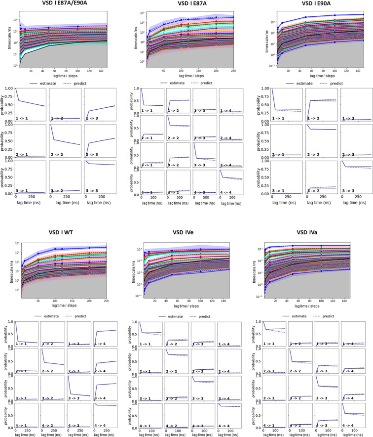
Figure 2—figure supplement 3. Parameter selection and validation of the Markov state models (MSMs) corresponding to the results presented in Figures 2, 4, and 5.

Figure 2—figure supplement 3.

Implied timescales as function of lag time for each system (top). A lag time of 100 steps has been selected to build the MSM. The Chapman-Kolmogorov tests (bottom) for the respective MSM of each voltage sensing domain (VSD) demonstrate the reliability of our MSM. The individual panels of the Chapman-Kolmogorov tests show transitions between two states as labeled respectively. The x-axis denotes multiples of the lag time and the y-axis represents the probability. The plots show a comparison between MSMs estimated at higher lag times and depict extrapolations of the MSMs at a single lag time.
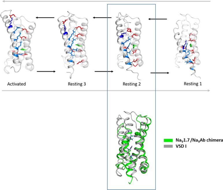
Figure 2—figure supplement 4. Structural comparison of the CaV1.1 voltage sensing domain (VSD) I resting states with the experimentally determined resting state structure of a NaV1.7/NaVAb chimera.

Figure 2—figure supplement 4.

Comparison of the cryo-electron microscopy (cryo-EM) structure of VSD II of NaV1.7/NaVAb stabilized in a resting state by toxin binding (PDB accession code 6N4R) (Xu et al., 2019) (green), with the resting states of CaV1.1 VSD I obtained by our molecular dynamics (MD) simulation. We observed the highest structural similarity of the VSD II of NaV1.7/NaVAb with our resting state 2 (gray) (Cα root-mean-square deviation [RMSD] of 1.9 Å).
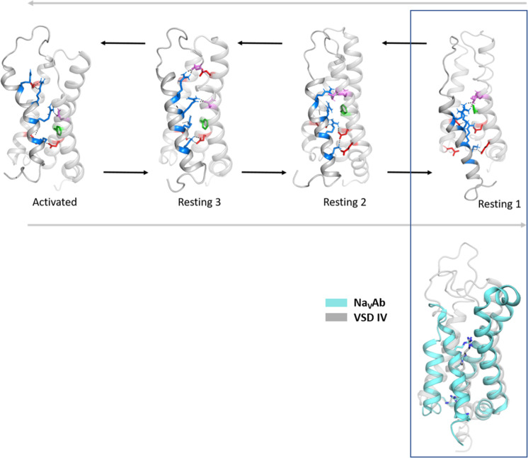
Figure 2—figure supplement 5. Structural comparison of the CaV1.1 voltage sensing domain (VSD) IV resting states with the experimentally determined resting state structure of NaVAb.

Figure 2—figure supplement 5.

Comparison of the cryo-electron microscopy (cryo-EM) structure of VSD of NaVAb stabilized in a resting state by toxin binding (PDB accession code 6P6W) (Wisedchaisri et al., 2019) (cyan), with the resting states of CaV1.1 VSD IV obtained by our molecular dynamics (MD) simulation. We observed the highest structural similarity of the NaVAb VSD with our resting state 1 (gray) (Cα root-mean-square deviation [RMSD] of 1.7 Å).

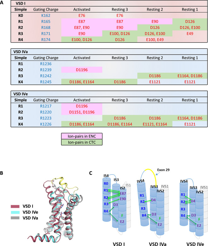
Figure 3. Ion-pair partners of CaV1.1 voltage sensing domains (VSDs) I and IV gating charges in activated and resting states.

Figure 3.

(A) Tabular overview of ion-pair interactions of the positive gating charges (blue) with countercharges (red) observed in the activated and three resting states of VSDs I, IVa, and IVe. Fields shaded in green show the sequential interaction with the ion-pair partners of the intracellular negative cluster (INC). In VSD I this transition through the charge transfer center (CTC) involves R4, R3, R2, R1, whereas in VSD IV only R4 and R3 participate in equivalent interactions. Ion-pair formation with the extracellular negative cluster (ENC) (pink shading) of VSD I involved three gating charges (R3, R2, R1) in the activated and intermediate resting states 2 and 3. In VSD IV ion-pair formation with the ENC is limited to the activated state, and it is further reduced by inclusion of exon 29 in VSD IVa. (B) Structure overlay of VSD I, VSD IVa (including exon 29; yellow), and VSD IVe in the activated state. (C) Schematic representation of the three VSDs indicating similar ion-pair formation in the INC, representing the conserved CTC (dark green), but highly distinct ion-pair formation in the ENC (light green) of the three analyzed VSDs.

Next, we used MSM of the MD simulation data to estimate transition times between the resting and activated states during the activating and deactivating VSD motion (Figure 2B,D; Figure 2—figure supplement 3; Supplementary file 1). The conformational transitions between the different activation states of CaV1.1 VSD I occurred in the high µs to low ms timescale. Because the values calculated in our model are obtained in the absence of the force provided by changes in the electric field, the absolute transition times derived from MSM may not correspond to the actual transition times of the VSD upon physiological activation and deactivation. Nevertheless, relative differences between transition times provide meaningful information when compared between different VSDs or functionally different mutants (see below). Relying on a simple transition state theory model (Laidler and King, 1983), we generated a schematic 1D representation of the high-dimensional free energy surface (Figure 2D), allowing an intuitive interpretation of free energy levels of the states and ΔG of the energy barriers. The free energy of the activated state was the lowest and transitions in the activating direction were two to four times faster than in the deactivating direction, consistent with the fact that our MD simulations were performed on structure models at a depolarized membrane (0 mV), which favors the activated state of the VSDs. The energy barriers (ΔG) for the three state transitions of VSD I in the activating direction were between 48 and 51 kJ/mol.

MD simulation and MSM of VSD IV in activated and resting states

How do the molecular interactions during VSD activation and deactivation and the kinetics of state transition differ between VSD I and VSD IV to explain their distinct functions in determining kinetics and voltage dependence of activation, respectively? (Tuluc et al., 2009) The basic structural features of the activated and resting states of VSD IV corresponded to those of VSD I, except that in VSD IV the translocation of S4 across the HCS covered a shorter distance and involved fewer ion-pair interactions (Figure 2F,G,J,K). Upon the deactivating motion of the S4 helix of VSD IV, only a single gating charge (R3) fully translocated from a position above the HCS (F1161) to below it. Accordingly, the total vertical displacement in the two splice variants of IVS4 was 12.9 Å in VSD IVe and only 10.2 Å in VSD IVa, corresponding to roughly two helical turns.

In the four states of both VSD IV variants, only the two inner gating charges R3 and K4 sequentially interacted with the conserved ion-pair partners of the charge transfer center (E1164 and D1186) (Figure 2F,J; Figure 3A). R2 moved into the HCS but did not form ion pairs with E1164 or D1186. In the deep resting states, an additional ion pair was formed between K4 and E1121 at the cytoplasmic end of IVS1. At variance with VSD I, ion-pair formation of the outer gating charges of VSD IV was completely absent in the resting states. Instead, R1 and R2 established several weaker hydrogen bonds with side chains of uncharged polar amino acids. In VSD IV ion-pair interactions of R1 and R2 with the ENC were limited to the activated state of the CaV1.1e splice variant. Within VSD IV they were established with a single ion-pair partner (D1196), the functional importance of which for splicing-dependent regulation of the voltage dependence of activation had been shown previously (Tuluc et al., 2016b). Consistent with that study, these interactions were greatly attenuated when exon 29 was included in the IVS3-S4 linker of CaV1.1a (Figure 3A,C). The activated state structure of VSD IVa (containing exon 29) showed only a single H-bond between R2 and D1196, compared to two each of R1 and R2 with D1196 in VSD IVe (lacking exon 29). Thus, the three resting states of VSD IV are not stabilized by ion pairs formed by the outer gating charges, and the ion-pairs forming in the activated state are further reduced by inclusion of exon 29 in the linker separating the two participating helices.

Can these striking structural differences explain the kinetic differences conferred to the channel by VSDs I and IV? Our MSM calculations of state transition kinetics strongly support this notion. Compared to VSD I, the energy barriers between the states were substantially lower in VSD IV (35–38 kJ/mol for IVe and 35–42 kJ/mol for IVa) (Figure 2H,L). Consistent with the differences in activation kinetics, the transition times determined for VSD IV were in the µs range (Figure 2F,J), which is two to three orders of magnitude faster than those of VSD I. Also, the transitions between resting states 1 and 2, and between resting state 3 and the activated state were about three times faster in CaV1.1a compared to CaV1.1e, indicating an effect of exon 29 insertion on the kinetics of VSD IV movement. However, compared to the substantial difference between the kinetically distinct VSDs I and IV, the differences in energy barriers and transition times between the two VSD IV splice variants remain unexpectedly small. Apparently, the calculated transition times primarily reflect differences in kinetics, but much less differences of the voltage dependence of activation. This makes sense, considering that the height of energy barriers and the transition kinetics are expected to affect the sequential transitions of a VSD through all four states, which determine the channel activation kinetics, whereas changes in voltage sensitivity primarily rely on the stabilization of the activated state and therefore are little affected by differences of the state transitions.

The direct comparison of VSD I and the two splice variants of VSD IV in the activated and resting states demonstrates striking differences between VSDs I and IV in the extent of ion-pair formation in the ENC (Figure 3). As shown above, in VSD IV these involve interaction of R1 and R2 with the ion-pair partner D1196 in IVS3 formed in the activated state that is subject to modulation by alternative splicing of exon 29. VSD I lacks an analogous ion-pair partner in the corresponding position of IS3. Instead IS4 displays extensive ion pairs with countercharges (E76, E87, E90) in IS2 that are sequentially formed by gating charges R3, R2, R1, and K0 in the activated and the intermediate resting states 2 and 3 (Video 1). This indicates that in VSDs I and IV, the gating charges above the HCS utilize structurally distinct ion-pair partners to stabilize the voltage sensor either only in the activated state (VSD IV) or in the activated and resting states (VSD I). The additionally formed ion pairs in the resting states of VSD I are paralleled by a remarkable increase in the energy barriers and the state transition times, suggesting that the number and strength of interactions between the gating charges and the ENC transiently formed in the resting states determine the slow activation kinetics of VSD I.

Video 1. Movement of wildtype CaV1.1e voltage sensing domain (VSD) I upon activation and deactivation, highlighting the ion-pair interactions formed between the S4 gating charges (blue) and relevant countercharges (red) in the S2 and S3 helices.

Download video file (3.1MB, mp4)

VSD I ion pairs differentially regulate gating properties

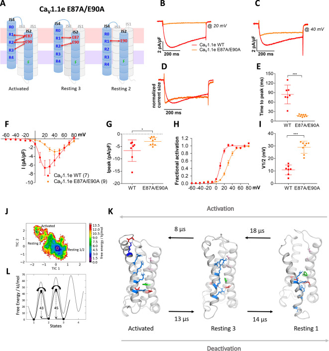
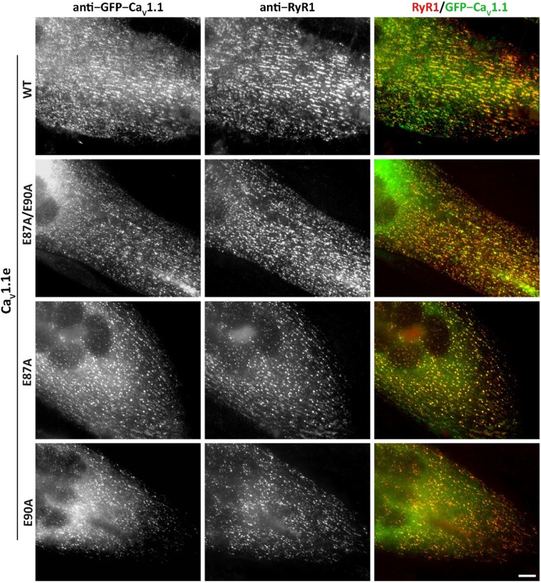
To experimentally test this hypothesis, we simultaneously mutated both countercharges, E87 and E90, to alanine (E87A/E90A) in the rabbit GFP-CaV1.1e (Tanabe et al., 1988; Tuluc et al., 2009), expressed them in their native environment in dysgenic myotubes and examined the effects on the gating properties of its calcium currents (Figure 4A). The structure of the VSDs in general and in particular the studied residues are highly conserved in CaV channels (Wu et al., 2016). Immunofluorescence labeling demonstrated that wildtype (WT) and mutant channels were equally expressed and targeted to triad junctions in the myotubes (Figure 4—figure supplement 1). In contrast, their gating properties differed significantly (Figure 4B–I; Supplementary file 1). As hypothesized, activation kinetics was more than four times faster in the mutant compared to WT (Figure 4D,E), thus identifying E87 and/or E90 as critical determinants of the slow activation kinetics of CaV1.1. Interestingly, also the voltage dependence of activation was right-shifted to more depolarizing potentials by 18.2 mV and the peak current density was somewhat reduced (Figure 4F–I).

Figure 4. Countercharges E87 and/or E90 in IS2 determine the voltage dependence and kinetics of CaV1.1 current activation and voltage sensing domain (VSD) transitions.

(A) Schematic model of VSD I in the activated and resting states, showing the putative loss of interactions between gating charges and countercharges E87 and E90 upon their mutation to alanine. (B–I) In CaV1.1e the double mutation E87A/E90A (orange) accelerated activation kinetics and right-shifted the voltage dependence of activation, compared to wildtype (WT) CaV1.1e (red). (B,C) Representative current traces at Vmax of WT CaV1.1e (20 mV) and CaV1.1e E87A/E90A (40 mV), respectively, and normalized currents at Vmax (D). (E) Scatter plot of the time to peak; (F) current-voltage relationship; (G) scatterplot of maximum current density (p=0.03); (H) voltage dependence of activation; (I) scatter plot of the voltage at half-maximal activation (V½). Mean ± SEM; p-values calculated with Student’s t-test, ***p<0.00001. (J,K) The time-lagged independent component analysis (tICA) free energy surface of CaV1.1e E87A/E90A displays three macrostates with structures corresponding to the activated state and resting states 1 and 3, and transition kinetics in the low μs timescale. (L) The 1D energy plot shows substantially lower calculated energy barriers between the states of the double mutant (black) compared to the WT VSD I (gray).

Figure 4.

Figure 4—figure supplement 1. Expression and triad targeting of wildtype (WT) and E87A, E90A mutant GFP-CaV1.1e channels in dysgenic myotubes.

Figure 4—figure supplement 1.

Dysgenic (CaV1.1-null) myotubes were transfected with the indicated GFP-CaV1.1e constructs and myotubes were fixed and double immunofluorescence labeled with anti-GFP (to localize the CaV1.1 construct) and anti-RyR1 (as a triad marker). Colocalization of GFP-CaV1.1e constructs with RyR1 in clusters indicates its normal incorporation into triadic calcium channel complexes of skeletal myotubes. All three used GFP-CaV1.1e mutants (E87A/E90A, E87A, and E90A) showed similar expression and distribution as the WT GFP-CaV1.1e. Scale bars, 10 µm.
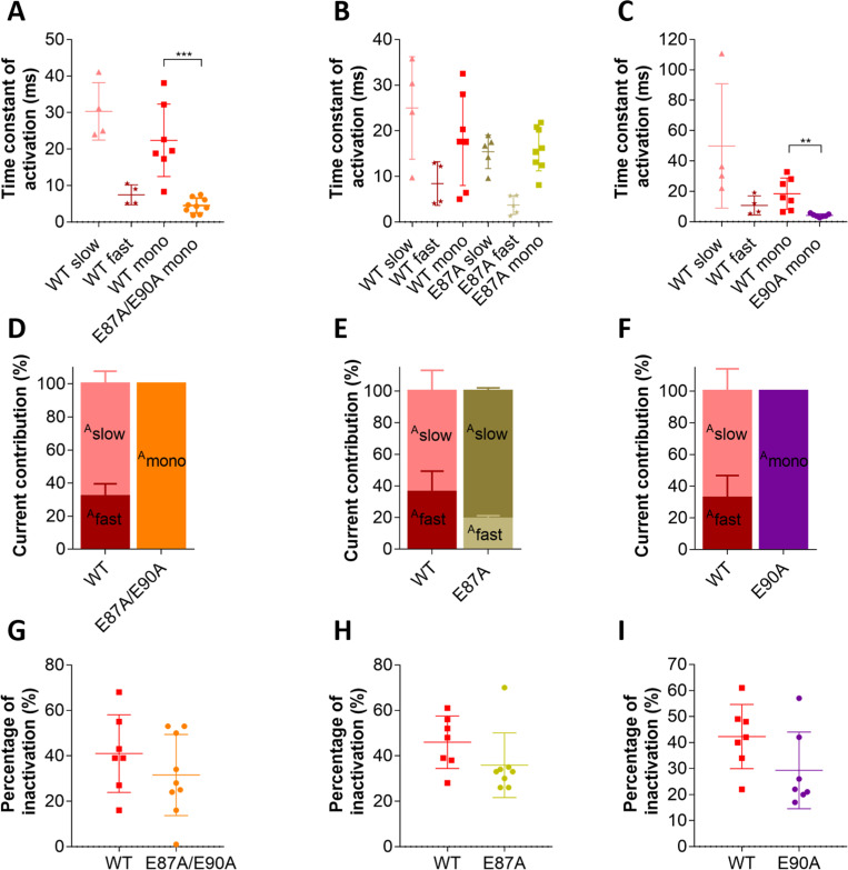
Figure 4—figure supplement 2. Putative countercharge E90, but not E87, determines slow activation kinetics of voltage sensing domain (VSD) I of CaV1.1e.

Figure 4—figure supplement 2.

(A–C) Scatter plots of the time constant of activation, when fitted to a bi-exponential function (fast and slow component) or to a mono-exponential function (mono). (A) This scatter plot shows that, when countercharges E87 and E90 are simultaneously neutralized, kinetics of activation becomes best described by a mono-exponential function due to the loss of the slow component; this time constant of E87A/E90A is faster than that of the mono-exponential fit of CaV1.1e wildtype (WT) (WT mono, red; E87A/E90A mono, orange; p=0.0003 calculated with the Student’s t-test) and even faster than WT fast (maroon) when CaV1.1e WT activation is fitted to a bi-exponential function. (B) The scatter plot for E87A shows that, when only this countercharge is neutralized, activation is still best fitted to a bi-exponential function as in CaV1.1e WT. No significant differences were found between WT slow vs. E87A slow (p=0.24, Student’s t-test) and WT fast vs. E87A fast (p=0.20, Student’s t-test). When activation is forced to a mono-exponential function, no differences were found between WT mono and E87A mono (p=0.84, Student’s t-test). (C) When countercharge E90 alone is neutralized, kinetics of activation is best described by a mono-exponential function due to a complete loss of the slow component; the time constant of E90A is faster than the mono-exponential fit of CaV1.1e WT (WT mono, red; E90A mono, purple; p=0.003) and even faster than WT fast (maroon) when CaV1.1e WT activation is fitted to a bi-exponential function. (D–F) Bar graphs show the current contribution of the slow vs. fast component of activation, when fitted best to a bi-exponential function (CaV1.1e WT in D, E, and F and CaV1.1e E87A in E). (D) CaV1.1e WT is best fitted to a bi-exponential function with a 31.9:68.1% ratio of fast:slow. CaV1.1e E87A/E90A can only be described by a mono-exponential function, indicating a 100% contribution of the fast component. (E) Activation of both CaV1.1e WT and E87A are best described bi-exponentially, with a somewhat bigger current contribution of the slow component (Aslow) in the mutant (Aslow WT vs. E87A is 63.8% vs. 80.8%, p=0.052 calculated with the Student’s t-test). (F) E90A can only be described by a mono-exponential function, indicating a loss of the slow component. (G–I) Scatter plots showing the fractional inactivation at the end of the 500 ms test pulse. None of the mutations affected the inactivation properties of CaV1.1 (p-values calculated with the Student’s t-test are 0.31 in G, 0.16 in H, and 0.10 in I, see Supplementary file 1).

If the comparably long transition times for WT VSD I determined by MSM related to the experimentally determined activation kinetics, then MSM of the E87A/E90A mutant channel should result in rapid transition times. This was indeed the case! The transition times of VSD I on activation and deactivation of the E87A/E90A mutant were more than 50 times faster than those of the WT VSD (Figure 4J–L; Figure 2—figure supplement 3, Figure 4—figure supplement 2, Supplementary file 1; Videos 1 and 2). This supports our interpretation of the role of the two countercharges in determining the gating properties, and also substantiates the reliability and predictive value of the kinetic analysis of our MD simulations. Yet, it is worth noting that the transition kinetics derived from our MD simulation relate to the activation of an isolated VSD, whereas kinetics and voltage dependence of channel activation reflect the concerted action of all four VSDs and its mechanical transduction to the channel gate. Consequently, changes in activation properties of a single VSD will only result in similar changes of current activation, when this VSD is obligatory and rate-limiting for gating, or, in an allosteric model, according to its relative contribution to the gating process. This limitation may also account for the different magnitudes of the effects (50-fold vs. 5-fold) on the activation kinetics of the E87A/E90A mutant observed in MSM and current recordings.

Video 2. Movement of the E87A/E90A double mutant of CaV1.1e voltage sensing domain (VSD) I upon activation and deactivation, highlighting the ion-pair interactions formed between the S4 gating charges (blue) and relevant countercharges (red) in the S2 and S3 helices.

Download video file (1.9MB, mp4)

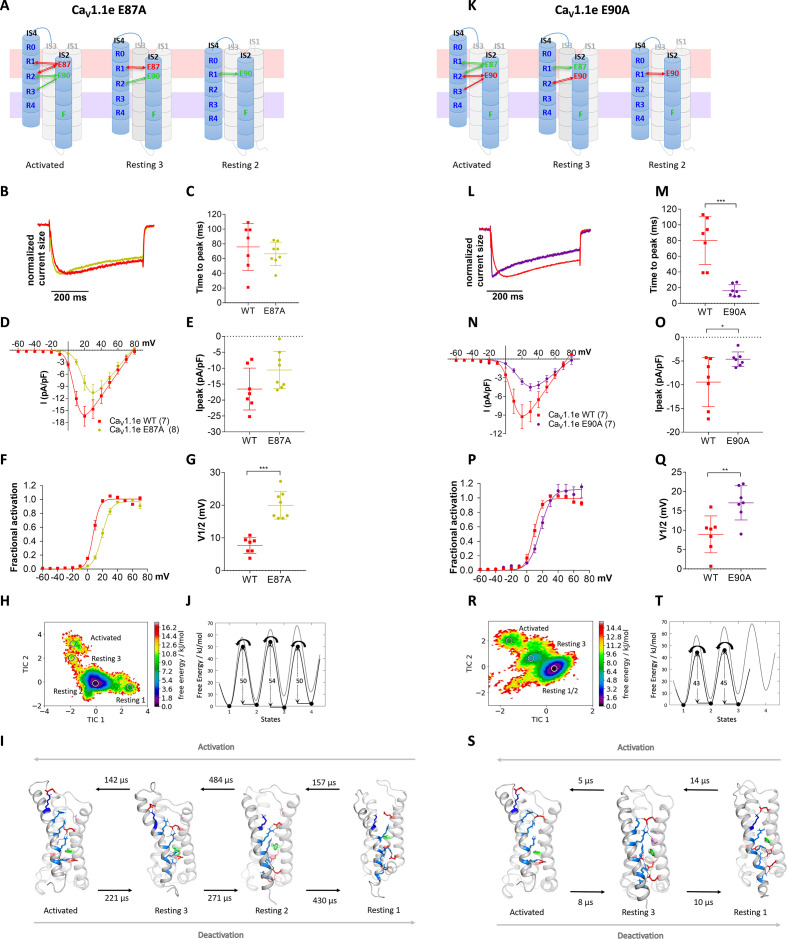
As E87 and/or E90 govern the kinetics as well as voltage dependence of CaV1.1 activation, we wondered whether these two properties are mechanistically linked to each other or separable? Our structural model predicts that E87 interacts with R1 in resting state 3, and with R1 and R2 in the activated state (Figure 5A), which is consistent with a prime role in stabilizing the activated state. In contrast, E90 forms consecutive interactions with R3, R2, and R1 in resting state 2, resting state 3, and the activated state, respectively (Figure 5K), thus stabilizing VSD I both in its resting and activated states. To examine the individual contributions of E87 and E90 to shaping the gating properties, we generated constructs with individual E87A and E90A substitutions. The two mutations showed differential effects on the gating properties of CaV1.1 currents. The E87A mutation right-shifted the voltage dependence of activation by 12.3 mV, while activation kinetics were not altered (Figure 5B–G). In contrast, the E90A mutation accelerated the activation kinetics four- to fivefold and showed a 7.7 mV right-shift of voltage dependence (Figure 5L–Q).

Figure 5. Countercharges E87 and E90 differentially regulate kinetics of voltage sensing domain (VSD) I transitions and current activation.

(A,K) Schematic of VSD I in activated and resting states, showing the loss of ionic interactions upon mutation of E87A or E90A. (B–G) In CaV1.1e E87A right-shifted voltage dependence of activation without affecting kinetics (wildtype [red], E87A [lime]). (L–Q) The E90A mutation accelerated kinetics >4-fold and right-shifted voltage dependence of activation (wildtype [red], E87A [purple]). (B,L) Normalized representative currents show acceleration of activation in E90A (L) but not in E87A (B). (C,M) Time to peak (p=0.47 in C, p=0.00017 in M); (D,N) current-voltage relationship; (E,O) maximum current density (p=0.08 in E, p=0.04 in O); (F,P) voltage dependence of activation; (G,Q) voltage at half-maximal activation (V½) (p=0.000014 in G, p=0.008 in Q). Mean ± SEM; p-values calculated with Student’s t-test. (H–J) The time-lagged independent component analysis (tICA) free energy surface and schematic 1D representation of E87A show four macrostates corresponding to resting states 1, 2, 3 and the activated state with energy barriers similar to wildtype (gray) and transition kinetics in the higher μs timescale. (R–T) E90A shows three macrostates corresponding to the resting states 1 and 3 and the activated state, reduced energy barriers, and transition kinetics in the low μs timescale.

Figure 5.

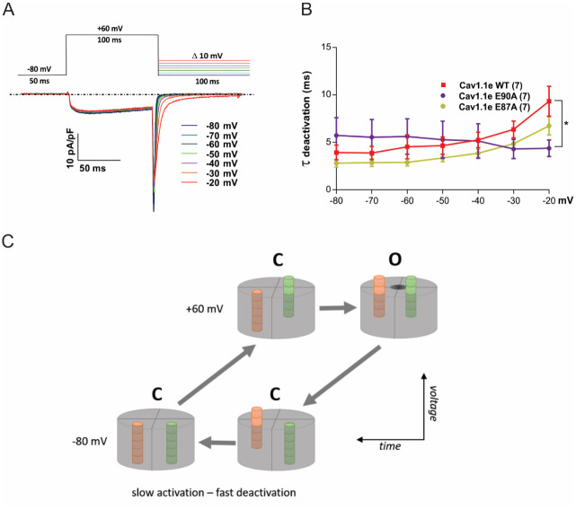
Figure 5—figure supplement 1. Deactivation kinetics are fast in CaV1.1e wildtype (WT) and in slowly (E87A) and fast-activating (E90A) voltage sensing domain (VSD) I mutants.

Figure 5—figure supplement 1.

(A) Voltage clamp protocol used to examine deactivation kinetics (top) and representative current traces (bottom). Upon repolarization from +60 mV to varying negative potentials (at 10 mV increments), activated channels conduct a transient inward calcium current (downward spike) before they deactivate and close the channel pore. The decay of this so-called tail current was fitted with a mono-exponential function to determine the time constants of deactivation. (B) The time constants of deactivation are equally fast in CaV1.1e WT, E90A, and E87A (in contrast to their distinct activation kinetics; cf. Figure 5—figure supplement 2). At −20 mV significant kinetic differences start to occur, because at such weak repolarization part of the channels fail to deactivate and thus contaminate the tail current with a slowly inactivating current component (p=0.019; two-way repeated measures ANOVA and Holm-Sidak post hoc test). (C) Simplified model explaining slow activation and fast deactivation of the channel. We assume that at least two VSDs need to be in the up-state for the channel gate to open (at +60 mV). In response to the depolarizing voltage step, the slow VSD (orange; VSD I in CaV1.1) will be rate-limiting and thus endow the channel with slow activation kinetics. On repolarization, the rapid downward movement of another VSD (green) will close the channel gate with fast deactivation kinetics, thus masking the continuing downward movement of the slow VSD.

Again, MD simulation and MSM analysis reflected these differential functional effects. In accordance with its effect on activation kinetics, the E90A mutation, but not E87A, showed greatly accelerated transition times and reduced energy barriers between the resting and activated states (Figure 5H–J and R–T). Furthermore, the free energy maps of all three mutations showed shallower energy wells in the activated states, consistent with their reduced stabilization and their right-shifted voltage dependence of current activation. Also, compared to WT VSD I, the three mutants displayed a decreased drop of the energy minima (ΔG) from resting state 3 to the activated state (Figure 4L and Figure 5J,T; Figure 4—figure supplement 2; Supplementary file 1). In the two mutations affecting activation kinetics (E87A/E90A and E90A), resting states 1 and 2 collapsed into a single deep energy well (Figures 4J and 5R), consistent with the notion that in WT VSD I sequential formation of ion-pair interactions between E90 and R1, R2, and R3 is required to stabilize the separate resting states of VSD I, and that the transitions between these states slow down activation kinetics (Videos 14; Supplementary file 1). Thus, the structures derived from our simulations provide mechanistic explanations for how CaV channels determine their unique gating properties.

Video 3. Movement of the E87A mutant of CaV1.1e voltage sensing domain (VSD) I upon activation and deactivation, highlighting the ion-pair interactions formed between the S4 gating charges (blue) and relevant countercharges (red) in the S2 and S3 helices.

Download video file (3.3MB, mp4)

Video 4. Movement of the E90A mutant of CaV1.1e voltage sensing domain (VSD) I upon activation and deactivation, highlighting the ion-pair interactions formed between the S4 gating charges (blue) and relevant countercharges (red) in the S2 and S3 helices.

Download video file (2.1MB, mp4)

Notably, the differences of the transition kinetics observed in the MSM analysis between VSDs I and IV, and between WT VSD I and the E87A and E90A were manifested in the activating and deactivating direction (Figures 2, 4 and 5). However, patch clamp analysis of deactivation kinetics in WT and mutant VSD I did not reflect these differences (Figure 5—figure supplement 1). Upon repolarization to negative membrane potentials, the deactivation time constants of all tested constructs were between 4 and 10 ms and thus near the activation time constants of the fast activating mutants (E87A/E90A and E90A). This is expected considering the distinct dependence of channel activation and deactivation on the actions of multiple VSDs. Upon depolarization, the VSDs need to proceed through all resting states into the activated state before the channel gate will open. Inevitably, the speed of this action is limited by the slowest VSD necessary for channel opening (VSD I in the case of CaV1.1). In contrast, on deactivation the channel gate closes when the first essential VSD transits from the activated state into resting state 2 (Figure 5—figure supplement 1). Principally, this can be any one of the four VSDs. Therefore, channel deactivation will be rapid even if VSD I requires considerably more time to return to its deepest resting state, as predicted by our MSM analysis.

Discussion

Our advanced structure models of the activated and resting states of CaV1.1 VSDs fill an important gap in the understanding of the voltage sensing mechanism in eukaryotic voltage-gated cation channels. The results presented in this study demonstrate two surprisingly different VSDs, which substantially differ in the range of S4 helix displacement during activation/deactivation, as well as in the number and position of ionic bonds formed between the outer gating charges and countercharges of the ENC in the resting and activated states. These structural differences correspond to differences in the free energy states and kinetics of the state transitions, which in turn correlate with the experimentally determined kinetics and voltage dependences of current activation. Throughout this structure-function study, the combination of MD simulation and MSM proved to be of exceptionally high predictive value. All tested interaction partners suggested by the model showed the predicted effects on channel gating when experimentally tested by mutagenesis and electrophysiology analysis. Conversely, alterations of kinetic properties first recognized experimentally were reliably reproduced and explained by our computer model.

Overall, the structures of the lowest energy states of CaV1.1 VSDs display the basic features of the sliding helix model (Catterall et al., 2017) and of previous simulations of VSD structures (Tuluc et al., 2016b; Yarov-Yarovoy et al., 2012). Notably, two of the resting states predicted by our models closely correspond to recently described cryo-EM structures of homotetrameric NaV channels with the VSD in a down-state. Our resting state 1 structure of VSD IVa resembles a mutated NaVAb captured in the resting state by disulfide locking (Cα RMSD of 1.7 Å) (Figure 2—figure supplement 4Wisedchaisri et al., 2019). Our resting state 2 structure of VSD I resembles that of a NaVAb/NaV1.7 chimera stabilized in a deactivated state by toxin binding (Cα RMSD of 1.9 Å) (Figure 2—figure supplement 5Xu et al., 2019). Thus, the voltage sensing action of the eukaryotic CaV1.1 displays a remarkable similarity to that of its homotetrameric bacterial ancestor. Particularly, the sequential movement of the gating charges across the HCS and the stabilization of the states by their transient formation of ion pairs with negatively charged amino acids of the INC were similarly observed in VSDs I and IV. Evidently, these features represent highly conserved properties of voltage-gated cation channels (prokaryotic and eukaryotic) and probably define the essence of the voltage sensing mechanism.

In contrast, the interactions of the outer gating charges with the negatively charged amino acids of the ENC differed considerably between the two studied VSDs of CaV1.1, as well as between the two splice variants of VSD IV. Although the outer gating charges of both VSDs established such ion pairs, they used partners in different transmembrane segments (IS2 vs. IVS3). In both VSDs, the examined ion-pair partners of R1 proved to be crucial for stabilizing the voltage sensor in the activated state, as their mutations consistently resulted in a shift of the voltage dependence of activation to more depolarized voltages (El Ghaleb et al., 2019; Tuluc et al., 2016b). Furthermore, the ion-pair interactions in the two VSDs differed in the extent they were formed in different states. While in VSD IV such ion pairs were restricted to the activated state, in VSD I they were also found in resting states 2 and 3, leading to a substantially stronger stabilization of these resting states in VSD I compared to VSD IV. Concordantly, MSM and site-directed mutagenesis demonstrated that this stabilization of resting states in VSD I causes a dramatic slowing of state transitions and of activation kinetics characteristic for CaV1.1 currents, respectively. Apparently, the repeated formation and breaking of ionic bonds in consecutive resting states increases the energy barriers between the states and thus slows down the movement of IS4 to the activated state. In contrast, the weaker hydrogen bonds of the outer gating charges of IVS4, or mutation of ion-pair partners in IS3, support fast state transitions and current activation.

This indicates that the negative countercharges in the ENC serve a dual role in the voltage-gating process. They enable the hand-over-hand movement of the gating charges, thus guiding the state transitions of S4 across the membrane electric field, and they stabilize the VSD in the activated states. Accordingly, mutation of specific countercharges differentially affected the voltage dependence and kinetics of activation. While the charge-neutralizing mutation of E87 in IS2, which stabilizes the VSD I in the activated state, perturbed the voltage dependence of activation, mutating E90, which also forms ionic bonds with R1 and R2 in the resting states, accelerated the activation kinetics. MD simulation and MSM suggested that the loss of the stabilizing interactions with the negative countercharge E90 causes the collapse of resting states 1 and 2, thereby enhancing the speed of VSD I transition into the activated state. As E90 also contributed to stabilizing the activated state, its mutation also caused a right-shift of the voltage dependence of activation. The importance of activated-state-stabilizing interactions of the outermost gating charges for specifically setting the voltage dependence of activation is consistent with earlier mutagenesis experiments of R1 in VSD I and of R1, R2, and D1196 in VSD IV, all of which right-shifted voltage dependence without changing activation kinetics (El Ghaleb et al., 2019; Tuluc et al., 2016b). Unlike VSD I, VSD IV establishes stabilizing ion pairs exclusively in the activated state. The lack of stabilizing ion pairs in the resting states is consistent with the intrinsically fast activation kinetics of this VSD. However as in VSD I, weakening the countercharges in IVS3 either physiologically, by insertion of exon 29 in the IVS3-S4 linker, or experimentally, by mutagenesis, caused a right-shift of the voltage dependence of activation with little effect on kinetics (Tuluc et al., 2016b). Thus, ion-pair formation of R1 with E87 and E90 in VSD I, and of R1 in VSD IV with D1196 are functionally equivalent in stabilizing the activated state in both VSDs, whereas ion-pair formation of multiple gating charges with E90 that stabilize the resting states is specific for VSD I and represents the structural correlate of CaV1.1 slow activation.

If the outward motion of the S4 helix with the sequential stabilization of the inner gating charges by ion-pair formation with the INC is the general theme of the voltage sensing process, the interactions between the outer gating charges with countercharges of the ENC represent the variations to this theme. They differ in number, strength, and position from analogous interactions described in the structures of other channels, and even between the VSDs of a single channel. Importantly, in which states they are established determines which biophysical properties of channel gating are being modulated. The general principle derived from our modeling and mutagenesis experiments is that stabilization of VSDs in the activated state supports channel opening by shifting the voltage dependence of activation to more hyperpolarizing potentials. On the other hand, ion-bond formation between the gating charges and the ENC in resting states delays channel opening by slowing down the activation kinetics. Interestingly, at least in CaV1.1, these actions are divided between separate VSDs. Thus, our findings provide a molecular mechanism explaining how channels using the same general voltage sensing mechanism can produce very distinct gating properties and how in pseudo-tetrameric eukaryotic voltage-gated cation channels the distinct VSDs cooperate in establishing the characteristic gating properties.

Materials and methods

Key resources table.

Reagent type (species) or resource Designation Source or reference Identifiers Additional information
Gene (human) CACNA1S Wu et al., 2016 Q13698
Gene (rabbit) CACNA1S Grabner et al., 1998 P07293
Cell line (mouse) GLT, dysgenic skeletal myotubes Powell et al., 1996 GLT; mdg/mdg CaV1.1-null
Transfected construct (rabbit) GFP-CaV1.1e
(wild type)
Tuluc et al., 2009 CaV1.1-
D exon 29
Transfected construct (rabbit) GFP-CaV1.1e
-E87A/E90A, -E87A, -E90A
This paper
Antibody Rabbit polyclonal anti-GFP Invitrogen
Thermo Fisher
A-6455, RRID:AB_221570 IF (1:10,000)
Antibody Mouse monoclonal anti-RyR Invitrogen
Thermo Fisher
(MA3-925) 34 C
RRID: AB_2254138
IF (1:500)
Software, algorithm AMBER simulation software AmberMD RRID: SCR_014230
Software, algorithm AmberTools 19 AmberMD RRID: SCR_018497
Software, algorithm PyMOL Schrödinger RRID: SCR_000305
Software, algorithm Clampex Clampex Version 10.2 RRID:SCR_011323
Software, algorithm Clampfit Clampfit Version 10.7 RRID:SCR_011323
Software, algorithm SigmaPlot SigmaPlot Version 12.0 RRID:SCR_003210
Software, algorithm GraphPad Prism GraphPad Prism Version 7 RRID:SCR_002798

Homology model of the CaV1.1 α1 subunit

We predicted the structure of the human WT CaV1.1 α1 subunit by making a homology model based on the cryo-EM structure of the rabbit CaV1.1 α1 subunit with the VSDs in the up-state and the pore closed (Wu et al., 2016). Homology modeling has been performed using Rosetta and MOE (Molecular Operating Environment, version 2018.08, Molecular Computing Group Inc, Montreal, Canada). The sequence identity between the rabbit and the human CaV1.1 α1 subunit is 92.6%, the sequence similarity even 95.6%. Because of the high sequence similarity and identity between the human and the rabbit CaV1.1, we generated only 10 homology models and chose the one model with the best energy score as starting structure for further minimizations, equilibrations, and simulations. The fragment-based cyclic coordinate descent algorithm implemented in Rosetta was used to generate structures for loops that were not resolved in the CaV1.1 α1 subunit template (Supplementary file 1; input scripts – IS1, Canutescu and Dunbrack, 2003; Wang et al., 2007). The C-terminal and N-terminal parts of each domain were capped with acetylamide and N-methylamide to avoid perturbations by free charged functional groups. The structure model was embedded in a plasma membrane consisting of POPC (1-palmitoyl2-oleoyl-sn-glycero-3-phosphocholine) and cholesterol in a 3:1 ratio, using the CHARMM-GUI Membrane Builder (Jo et al., 2009). Water molecules and 0.15 M NaCl were included in the simulation box. Energy minimizations of the WT and the mutants in the membrane environment were performed. The topology was generated with the tleap tool of the AmberTools18 (Case et al., 2018), using force fields for proteins and lipids, ff14SBonlysc and Lipid14 (Dickson et al., 2014), respectively. The WT and mutant structures were heated from 0 to 300 K in two steps, keeping the lipids fixed, and then equilibrated over 1 ns. Then MD simulations were performed for 10 ns, with time steps of 2 fs, at 300 K and in anisotropic pressure scaling conditions as suitable for membrane proteins. Van der Waals and short-range electrostatic interactions were cut off at 10 Å, whereas long-range electrostatics were calculated by the particle mesh Ewald method. A hierarchical clustering was performed on the 10 ns trajectory using an RMSD distance cut-off criterion of 2.5 Å, resulting in three clusters. We chose the highest populated cluster representative for all further steps. PyMOL Molecular Graphics System was used to visualize the key interactions and point out differences in the WT and mutant structures (PyMOL Molecular Graphics System, version 2.0, Schrödinger, LLC).

Enhanced sampling and MD simulation protocol

Because high-resolution structures of resting states of CaV and NaV channels are still lacking, we applied MD simulation and MSM of individual VSD in the context of the whole channel to predict the structures and energy levels of resting states (Chodera and Noé, 2014). The workflow of the modeling procedure is summarized in Figure 2—figure supplement 1. To overcome the high energy barriers and the timescale limitations of MD simulations, we applied Umbrella sampling as enhanced sampling technique. As collective variable we used the distance between the S4 gating charge residues (R1, R2, and R3) and anchor residues at the intracellular helical ends of the VSDs located in S1 and S3, by using a force constant of the harmonic spring potential of 80 kcal/mol*Å2 to pull the S4 helix downward. Starting from the equilibrated structure, the Umbrella windows decreased between a distance of 24.0–14.0 Å using a step size of 1 Å. Each Umbrella window was simulated for 100 ns. After 20 ns of simulation time, the current conformation was extracted and used as starting structures for the next Umbrella window. The force constant of 80 kcal/mol*Å2 was determined to allow a sliding movement of S4 with minimal distortion of the VSDs. Additionally, we applied a weak backbone restraint on the φ torsion angle of the S4 helix of 50 kcal/mol*rad2 to guarantee a minimum of local artifacts of the Umbrella sampling process, that is, loss of secondary structure of the S4 helix. This combination of pulling and torsional restraint was tested and resulted in a sliding movement of the S4 helix without observing unfolding events. Note that the combination of restraints and Umbrella sampling does not result in equilibrium distributions, due to insufficient overlap between the individual sampling windows. Rather the Umbrella sampling was applied to generate conformations along a potential deactivation pathway; however, no states were pre-defined based on the Umbrella sampling. Hence, the Umbrella sampling was used as a mechanical force to pull the S4 helix in the absence of a membrane potential. To obtain the different activation and resting states, we used the resulting pathway of the combined Umbrella sampling trajectories and clustered it using a small distance cutoff criterion to also obtain cluster representatives at transition state regions. Using this procedure, we cannot exclude the possibility of other substantially different pathways (e.g., such that involve helix rotation and formation or breaking of interactions before or after S4 translocation). However, from our calculations we see no indications of the existence of such completely different pathways, which are kinetically accessible. Thus, to reconstruct the transition kinetics and to improve the sampling efficiency, we clustered the Umbrella sampling trajectories applying the program implemented in the AMBER suite cpptraj (Roe and Cheatham, 2013) by using the average linkage hierarchical clustering algorithm with an RMSD distance cutoff criterion of 1.2 Å resulting in a large number of clusters. The choice of the distance cutoff is optimized to obtain a broad cluster distribution within the conformational space of each VSD. The cluster representatives of the different activation states were equilibrated and simulated for 100 ns using the AMBER18 simulation package. For the resulting trajectories, a tICA was performed using the Python library PyEMMA 2 employing a lag time of 10 ns.

Construction of tICA and Markov state models is a dimensionality reduction technique, detecting the slowest relaxing degrees of freedom and facilitating the kinetic clustering, which is crucial for building an MSM (Pérez-Hernández and Noé, 2016). It linearly transforms a set of high-dimensional input coordinates to a set of output coordinates, by finding a subspace of good reaction coordinates. Thereby, tICA finds coordinates of maximal autocorrelation at a given lag time. The lag time sets a lower limit to the timescales considered in the tICA and the MSM.

Thermodynamics and kinetics were calculated with a Markov state model by using PyEMMA 2 (Scherer et al., 2015), which uses the k-means clustering algorithm to define microstates and the Perron Cluster Cluster Analysis (PCCA)+ clustering algorithm to coarse-grain the microstates to macrostates (Röblitz and Weber, 2013; Wu and Noé, 2020). The k-means clustering represents an iterative and robust clustering algorithm, which partitions the dataset into pre-defined distinct non-overlapping clusters, with the aim to make the intra-cluster points as similar as possible and keeping the subgroups as different as possible.

To construct coarse-grained models, the PCCA uses the eigenspectrum of a transition probability matrix. The eigenvectors corresponding to the Perron Cluster can be further used to coarse-grain an MSM. Here, we applied the PCCA+ clustering, as it is more robust than PCCA. PCCA+ tries to identify a set of indicator functions that can reproduce the slowest dynamical eigenvectors. PCCA+ relies on a maximum likelihood estimate of the transition.

To build the Markov state model, we used the Cα coordinates of the respective S4 transmembrane helix, defined 100 microstates using the k-means clustering algorithm and applied a lag time of 10 ns. The sampling efficiency and the reliability of the Markov state model (e.g., defining optimal feature mappings) can be evaluated with the Chapman-Kolmogorov test (Figure 2—figure supplement 4), by using the variational approach for Markov processes and by taking into account the fraction of states used, as the network states must be fully connected to calculate probabilities of transitions and the relative equilibrium probabilities (Likas et al., 2003). The construction of the MSM allows to quantify thermodynamic and kinetic properties of the resulting ensembles without the intrinsic bias resulting from the seeding process (Figure 2—figure supplement 1). The first stage of the MSM is to discretize the obtained conformational space into the so-called microstates, grouping together conformations of the system that can exchange rapidly (e.g., by k-means clustering). The aim is to construct a kinetically relevant clustering by using a geometric criterion, which still allows a quantitative connection with experiments, due to their high resolution. To identify the kinetic relevance of the clustering, an appropriate lag time, that is, observation interval, has to be chosen. This resulting microstate model can then be used as starting point for a kinetic clustering. To create a more understandable model, a kinetic clustering of a relevant set of microstates to the so-called macrostates can be performed, which are larger aggregates that correspond to the free energy wells (e.g., by PCCA+ clustering). The additional kinetic clustering into macrostates results in a more compact representation than the microstate model and thereby allows an easier processing and understanding of the conformational space. Thus, these qualitative models are ideal for generating new hypotheses, which can then be tested again with higher resolution models and experiments. The MSM was constructed by following the guidelines and input commands from the provided tutorial (http://www.emma-project.org/latest/tutorial.html#jupyter-notebook-tutorials).

To calculate the 1D free energy barriers K we used the obtained mean first passage times k from the MSM and calculated the barriers according to the transition state theory with the following equation:

k=kBThK

Expression plasmids

Cloning procedure for GFP-CaV1.1e WT was previously described (Tuluc et al., 2009). For better comparison with the literature, the non-corrected version of CaV1.1 was used. This CaV1.1 construct contains a lysine in position R1 of the VSD I, which results in a 12 mV left-shifted V½ compared to the construct with the evolutionary conserved arginine in position R1 (El Ghaleb et al., 2019). To generate the double mutant GFP-CaV1.1e-E87A/E90A and the single mutants GFP-CaV1.1e-E87A and GFP-CaV1.1e-E90A, aa E87 and E90 were neutralized by SOE-PCR (Supplementary file 5). Briefly, nt 1–1113 of the coding sequence of CaV1.1e (nt 226–1338 of CACNA1S NCBI reference sequence NM_001101720.1) were PCR-amplified with overlapping primers introducing the point mutation A > C at position nt 260 and/or the point mutation A > G at position nt 269 (nt 485 and nt 494, respectively, of NM_001101720.1) in separate PCR reactions using GFP-CaV1.1e-WT as template. The two separate PCR products were then used as templates for a final PCR reaction with flanking primers to connect the nucleotide sequences. This fragment was then SalI/EcoRI digested and cloned into the respective sites of GFP-CaV1.1e WT. Sequence integrity of the newly generated constructs was confirmed by sequencing (MWG Biotech, Martinsried, Germany).

Cell culture and transfection

Myoblasts of the dysgenic (mdg/mdg) cell line GLT were cultured as previously described in Powell et al., 1996. Briefly, cells were plated on 35 mm culture dishes and transfected with 0.5 μg of the desired CaV1 subunit 4 days after plating using FuGENE-HD transfection reagent (Promega). After 7–8 days in culture, transfected myotubes showing GFP fluorescence were analyzed by electrophysiology or fixed for immunolabeling after 9–10 days in culture. The auxiliary calcium channel subunits α2δ−1, β1a, and γ1, along with the STAC3 protein and ryanodine receptor, are endogenously expressed by GLT myotubes, enabling functional membrane incorporation of the channel constructs in the triad junction.

Immunofluorescence and antibodies

Paraformaldehyde-fixed cultures were immunolabeled as previously described (Flucher et al., 1994) with rabbit polyclonal anti-GFP (1:10,000; Invitrogen Thermo Fisher) and mouse monoclonal anti-RyR (34 C; 1:500; Invitrogen Thermo Fisher) and fluorescently labeled with goat anti-rabbit Alexa-488 and secondary goat anti-mouse Alexa-594 (1:4000), respectively. Thus, the anti-GFP label and the intrinsic GFP signal were both recorded in the green channel. Samples were observed using a 60×, 1.42 NA objective with a BX53 Olympus microscope and 14-bit images were captured with a cooled charge-coupled device camera (XM10, Olympus) and CellSens Dimension image-processing software (Olympus). Image composites were arranged in Adobe Photoshop CS6 (Adobe Systems Inc) and linear adjustments were performed to correct black level and contrast.

Electrophysiology and data analysis

Calcium currents were recorded with the whole-cell patch clamp technique in voltage clamp mode using an Axopatch 200A amplifier (Axon Instruments). Patch pipettes (borosilicate glass; Science Products) had resistances between 1.5 and 3.5 MΩ when filled with (mM) 145 Cs-aspartate, 2 MgCl2, 10 HEPES, 0.1 Cs-EGTA, and 2 Mg-ATP (pH 7.4 with CsOH). The extracellular bath solution contained (mM) 10 CaCl2, 145 tetraethylammonium chloride, and 10 HEPES (pH 7.4 with tetra-ethylammonium hydroxide). Data acquisition and command potentials were controlled by pCLAMP software (Clampex version 10.2; Axon Instruments); analysis was performed using Clampfit 10.7 (Axon Instruments) and SigmaPlot 12.0 (SPSS Science) software. The current-voltage dependence was fitted according to

I=Gmax(VVrev)/(1+exp((VV1/2)/k))

where Gmax is the maximum conductance of the L-type calcium currents, Vrev is the extrapolated reversal potential of the calcium current, V1/2 is the potential for half-maximal conductance, and k is the slope. The conductance was calculated using G = (− I * 1000)/(Vrev − V), and its voltage dependence was fitted according to a Boltzmann distribution:

G=Gmax/(1+exp((VV1/2)/k))

Statistical analysis

All four experimental groups were analyzed in transiently transfected cells from three to five independent cell passages. The E87A/E90A, E87A, and E90A variants of CaV1.1e were always recorded in parallel with the WT CaV1.1e in cells of the same passage to obtain the best controls for statistical comparison. Consequently, the values for WT controls vary slightly between conditions. The means, standard errors (SE), and p-values were calculated using the Student’s t-test, two-tailed, with significance criteria *p<0.05, **p<0.01, and ***p<0.001. Two-way repeated measures ANOVA, with the Holm Sidak post hoc test, was used to calculate p-values of deactivation.

Acknowledgements

We thank I Mahlknecht, N Kranebitter, M Bacher, and S Demetz for excellent technical support. The computational data have been obtained in part using the Vienna Scientific Cluster (VSC).

Funding Statement

The funders had no role in study design, data collection and interpretation, or the decision to submit the work for publication.

Contributor Information

Bernhard E Flucher, Email: bernhard.e.flucher@i-med.ac.at.

Toby W Allen, RMIT University, Australia.

Richard W Aldrich, The University of Texas at Austin, United States.

Funding Information

This paper was supported by the following grants:

  • Austrian Science Fund P30402 to Bernhard E Flucher.

  • Austrian Science Fund DOC30 to Bernhard E Flucher.

  • Austrian Science Fund T855 to Marta Campiglio.

Additional information

Competing interests

No competing interests declared.

Author contributions

Conceptualization, Data curation, Formal analysis, Investigation, Visualization, Methodology, Writing - review and editing.

Conceptualization, Data curation, Formal analysis, Investigation, Visualization, Methodology, Writing - review and editing.

Conceptualization, Formal analysis, Supervision, Writing - review and editing.

Supervision, Methodology.

Resources, Supervision, Methodology.

Conceptualization, Resources, Supervision, Funding acquisition, Writing - original draft, Project administration, Writing - review and editing.

Additional files

Supplementary file 1. Mean values and confidence intervals for probabilities and mean first passage times calculated from the Bayesian Markov state modeling (MSM), and the confidence intervals are calculated at a confidence level of 95%.
elife-64087-supp1.docx (30.3KB, docx)
Supplementary file 2. Current properties of E87A/E90A, E87A, E90A, and wildtype (WT) controls.
elife-64087-supp2.docx (14.6KB, docx)
Supplementary file 3. Linear interaction energy (LIE) calculations with the program cpptraj for the two voltage sensing domains (VSDs) and the mutants to calculate the electrostatic interactions of the S4 helix with all other parts of the voltage sensor.
elife-64087-supp3.docx (12.7KB, docx)
Supplementary file 4. Summary table of the modeled loops in the voltage sensors with ab initio Rosetta (Robetta).
elife-64087-supp4.docx (12KB, docx)
Supplementary file 5. Primers used for site-directed mutagenesis.
elife-64087-supp5.docx (12.6KB, docx)
Supplementary file 6. Input scripts.
elife-64087-supp6.docx (26.9KB, docx)
Transparent reporting form

Data availability

All data generated or analysed during this study are included in the manuscript and supporting files. The pdb structures of the models of the activated and the resting states of both the WT VSDs and the mutants are available from the Dryad server https://doi.org/10.5061/dryad.hhmgqnkfd.

The following dataset was generated:

Fernández-Quintero ML, El Ghaleb Y, Tuluc P, Campiglio M, Liedl KR, Flucher BE. 2020. Structural determinants of voltage-gating properties in calcium channels. Dryad Digital Repository.

References

  1. Ahern CA, Payandeh J, Bosmans F, Chanda B. The hitchhiker’s guide to the voltage-gated sodium channel galaxy. Journal of General Physiology. 2016;147:1–24. doi: 10.1085/jgp.201511492. [DOI] [PMC free article] [PubMed] [Google Scholar]
  2. Bender BJ, Cisneros A, Duran AM, Finn JA, Fu D, Lokits AD, Mueller BK, Sangha AK, Sauer MF, Sevy AM, Sliwoski G, Sheehan JH, DiMaio F, Meiler J, Moretti R. Protocols for molecular modeling with Rosetta3 and RosettaScripts. Biochemistry. 2016;55:4748–4763. doi: 10.1021/acs.biochem.6b00444. [DOI] [PMC free article] [PubMed] [Google Scholar]
  3. Canutescu AA, Dunbrack RL. Cyclic coordinate descent: a robotics algorithm for protein loop closure. Protein Science. 2003;12:963–972. doi: 10.1110/ps.0242703. [DOI] [PMC free article] [PubMed] [Google Scholar]
  4. Case DA, Ben-Shalom IY, Brozell SR, Cerutti DS, Cheatham TEI, Cruzeiro VWD, Darden TA, Duke RE, Ghoreishi D, Gilson MK, Gohlke H, Goetz AW, Greene D, Harris R, Homeyer N, Izadi S, Kovalenko A, Kurtzman T, Lee TS, LeGra S, York DM, Kollman PA. AMBER 2018. San Fransico: University of California; 2018. [Google Scholar]
  5. Catterall WA, Wisedchaisri G, Zheng N. The chemical basis for electrical signaling. Nature Chemical Biology. 2017;13:455–463. doi: 10.1038/nchembio.2353. [DOI] [PMC free article] [PubMed] [Google Scholar]
  6. Catterall WA, Lenaeus MJ, Gamal El-Din TM, El-Din TMG. Structure and Pharmacology of Voltage-Gated Sodium and Calcium Channels. Annual Review of Pharmacology and Toxicology. 2020;60:133–154. doi: 10.1146/annurev-pharmtox-010818-021757. [DOI] [PubMed] [Google Scholar]
  7. Chodera JD, Noé F. Markov state models of biomolecular conformational dynamics. Current Opinion in Structural Biology. 2014;25:135–144. doi: 10.1016/j.sbi.2014.04.002. [DOI] [PMC free article] [PubMed] [Google Scholar]
  8. Dickson CJ, Madej BD, Skjevik AA, Betz RM, Teigen K, Gould IR, Walker RC. Lipid14: the amber lipid force field. Journal of Chemical Theory and Computation. 2014;10:865–879. doi: 10.1021/ct4010307. [DOI] [PMC free article] [PubMed] [Google Scholar]
  9. El Ghaleb Y, Campiglio M, Flucher BE. Correcting the R165K substitution in the first voltage-sensor of CaV1.1 right-shifts the voltage-dependence of skeletal muscle calcium channel activation. Channels. 2019;13:62–71. doi: 10.1080/19336950.2019.1568825. [DOI] [PMC free article] [PubMed] [Google Scholar]
  10. Flucher BE, Andrews SB, Daniels MP. Molecular organization of transverse tubule/sarcoplasmic reticulum junctions during development of excitation-contraction coupling in skeletal muscle. Molecular Biology of the Cell. 1994;5:1105–1118. doi: 10.1091/mbc.5.10.1105. [DOI] [PMC free article] [PubMed] [Google Scholar]
  11. Flucher BE. Specific contributions of the four voltage-sensing domains in L-type calcium channels to gating and modulation. Journal of General Physiology. 2016;148:91–95. doi: 10.1085/jgp.201611663. [DOI] [PMC free article] [PubMed] [Google Scholar]
  12. Flucher BE. Skeletal muscle CaV1.1 channelopathies. Pflügers Archiv - European Journal of Physiology. 2020;472:739–754. doi: 10.1007/s00424-020-02368-3. [DOI] [PMC free article] [PubMed] [Google Scholar]
  13. Grabner M, Dirksen RT, Beam KG. Tagging with green fluorescent protein reveals a distinct subcellular distribution of L-type and non-L-type Ca2+ channels expressed in dysgenic myotubes. PNAS. 1998;95:1903–1908. doi: 10.1073/pnas.95.4.1903. [DOI] [PMC free article] [PubMed] [Google Scholar]
  14. Jensen MØ, Jogini V, Borhani DW, Leffler AE, Dror RO, Shaw DE. Mechanism of voltage gating in potassium channels. Science. 2012;336:229–233. doi: 10.1126/science.1216533. [DOI] [PubMed] [Google Scholar]
  15. Jo S, Lim JB, Klauda JB, Im W. CHARMM-GUI membrane builder for mixed bilayers and its application to yeast membranes. Biophysical Journal. 2009;97:50–58. doi: 10.1016/j.bpj.2009.04.013. [DOI] [PMC free article] [PubMed] [Google Scholar]
  16. Laidler KJ, King MC. Development of transition-state theory. The Journal of Physical Chemistry. 1983;87:2657–2664. doi: 10.1021/j100238a002. [DOI] [Google Scholar]
  17. Lenaeus MJ, Gamal El-Din TM, Ing C, Ramanadane K, Pomès R, Zheng N, Catterall WA. Structures of closed and open states of a voltage-gated sodium channel. PNAS. 2017;114:E3051–E3060. doi: 10.1073/pnas.1700761114. [DOI] [PMC free article] [PubMed] [Google Scholar]
  18. Likas A, Vlassis N, J. Verbeek J. The global k-means clustering algorithm. Pattern Recognition. 2003;36:451–461. doi: 10.1016/S0031-3203(02)00060-2. [DOI] [Google Scholar]
  19. Nakai J, Adams BA, Imoto K, Beam KG. Critical roles of the S3 segment and S3-S4 linker of repeat I in activation of L-type calcium channels. PNAS. 1994;91:1014–1018. doi: 10.1073/pnas.91.3.1014. [DOI] [PMC free article] [PubMed] [Google Scholar]
  20. Pan X, Li Z, Zhou Q, Shen H, Wu K, Huang X, Chen J, Zhang J, Zhu X, Lei J, Xiong W, Gong H, Xiao B, Yan N. Structure of the human voltage-gated sodium channel Nav1.4 in complex with β1. Science. 2018;362:eaau2486. doi: 10.1126/science.aau2486. [DOI] [PubMed] [Google Scholar]
  21. Pantazis A, Savalli N, Sigg D, Neely A, Olcese R. Functional heterogeneity of the four voltage sensors of a human L-type calcium channel. PNAS. 2014;111:18381–18386. doi: 10.1073/pnas.1411127112. [DOI] [PMC free article] [PubMed] [Google Scholar]
  22. Payandeh J, Scheuer T, Zheng N, Catterall WA. The crystal structure of a voltage-gated sodium channel. Nature. 2011;475:353–358. doi: 10.1038/nature10238. [DOI] [PMC free article] [PubMed] [Google Scholar]
  23. Pérez-Hernández G, Noé F. Hierarchical Time-Lagged independent component analysis: computing slow modes and reaction coordinates for large molecular systems. Journal of Chemical Theory and Computation. 2016;12:6118–6129. doi: 10.1021/acs.jctc.6b00738. [DOI] [PubMed] [Google Scholar]
  24. Powell JA, Petherbridge L, Flucher BE. Formation of triads without the dihydropyridine receptor alpha subunits in cell lines from dysgenic skeletal muscle. Journal of Cell Biology. 1996;134:375–387. doi: 10.1083/jcb.134.2.375. [DOI] [PMC free article] [PubMed] [Google Scholar]
  25. Röblitz S, Weber M. Fuzzy spectral clustering by PCCA+: application to markov state models and data classification. Advances in Data Analysis and Classification. 2013;7:147–179. doi: 10.1007/s11634-013-0134-6. [DOI] [Google Scholar]
  26. Roe DR, Cheatham TE. PTRAJ and CPPTRAJ: software for processing and analysis of molecular dynamics trajectory data. Journal of Chemical Theory and Computation. 2013;9:3084–3095. doi: 10.1021/ct400341p. [DOI] [PubMed] [Google Scholar]
  27. Rohl CA, Strauss CE, Misura KM, Baker D. Protein structure prediction using rosetta. Methods in Enzymology. 2004;383:66–93. doi: 10.1016/S0076-6879(04)83004-0. [DOI] [PubMed] [Google Scholar]
  28. Scherer MK, Trendelkamp-Schroer B, Paul F, Pérez-Hernández G, Hoffmann M, Plattner N, Wehmeyer C, Prinz JH, Noé F. PyEMMA 2: a software package for estimation, validation, and analysis of markov models. Journal of Chemical Theory and Computation. 2015;11:5525–5542. doi: 10.1021/acs.jctc.5b00743. [DOI] [PubMed] [Google Scholar]
  29. Tanabe T, Beam KG, Powell JA, Numa S. Restoration of excitation-contraction coupling and slow calcium current in dysgenic muscle by dihydropyridine receptor complementary DNA. Nature. 1988;336:134–139. doi: 10.1038/336134a0. [DOI] [PubMed] [Google Scholar]
  30. Tao X, Lee A, Limapichat W, Dougherty DA, MacKinnon R. A gating charge transfer center in voltage sensors. Science. 2010;328:67–73. doi: 10.1126/science.1185954. [DOI] [PMC free article] [PubMed] [Google Scholar]
  31. Tuluc P, Molenda N, Schlick B, Obermair GJ, Flucher BE, Jurkat-Rott K. A CaV1.1 Ca2+ channel splice variant with high conductance and voltage-sensitivity alters EC coupling in developing skeletal muscle. Biophysical Journal. 2009;96:35–44. doi: 10.1016/j.bpj.2008.09.027. [DOI] [PMC free article] [PubMed] [Google Scholar]
  32. Tuluc P, Benedetti B, Coste de Bagneaux P, Grabner M, Flucher BE. Two distinct voltage-sensing domains control voltage sensitivity and kinetics of current activation in CaV1.1 calcium channels. Journal of General Physiology. 2016a;147:437–449. doi: 10.1085/jgp.201611568. [DOI] [PMC free article] [PubMed] [Google Scholar]
  33. Tuluc P, Yarov-Yarovoy V, Benedetti B, Flucher BE. Molecular interactions in the voltage sensor controlling gating properties of CaV calcium channels. Structure. 2016b;24:261–271. doi: 10.1016/j.str.2015.11.011. [DOI] [PMC free article] [PubMed] [Google Scholar]
  34. Wang C, Bradley P, Baker D. Protein-protein docking with backbone flexibility. Journal of Molecular Biology. 2007;373:503–519. doi: 10.1016/j.jmb.2007.07.050. [DOI] [PubMed] [Google Scholar]
  35. Wisedchaisri G, Tonggu L, McCord E, Gamal El-Din TM, Wang L, Zheng N, Catterall WA. Resting State structure and gating mechanism of a Voltage-Gated sodium channel. Cell. 2019;178:993–1003. doi: 10.1016/j.cell.2019.06.031. [DOI] [PMC free article] [PubMed] [Google Scholar]
  36. Wisedchaisri G, Tonggu L, Gamal El-Din TM, McCord E, Zheng N, Catterall WA. Structural basis for High-Affinity trapping of the NaV1.7 Channel in Its Resting State by Tarantula Toxin. Molecular Cell. 2021;81:38–48. doi: 10.1016/j.molcel.2020.10.039. [DOI] [PMC free article] [PubMed] [Google Scholar]
  37. Wu J, Yan Z, Li Z, Yan C, Lu S, Dong M, Yan N. Structure of the voltage-gated calcium channel Cav1.1 complex. Science. 2015;350:aad2395. doi: 10.1126/science.aad2395. [DOI] [PubMed] [Google Scholar]
  38. Wu J, Yan Z, Li Z, Qian X, Lu S, Dong M, Zhou Q, Yan N. Structure of the voltage-gated calcium channel ca(v)1.1 at 3.6 Å resolution. Nature. 2016;537:191–196. doi: 10.1038/nature19321. [DOI] [PubMed] [Google Scholar]
  39. Wu H, Noé F. Variational approach for learning Markov processes from time series data. Journal of Nonlinear Science. 2020;30:23–66. doi: 10.1007/s00332-019-09567-y. [DOI] [Google Scholar]
  40. Xu H, Li T, Rohou A, Arthur CP, Tzakoniati F, Wong E, Estevez A, Kugel C, Franke Y, Chen J, Ciferri C, Hackos DH, Koth CM, Payandeh J. Structural basis of Nav1.7 Inhibition by a Gating-Modifier Spider Toxin. Cell. 2019;176:702–715. doi: 10.1016/j.cell.2018.12.018. [DOI] [PubMed] [Google Scholar]
  41. Yan Z, Zhou Q, Wang L, Wu J, Zhao Y, Huang G, Peng W, Shen H, Lei J, Yan N. Structure of the Nav1.4-β1 complex from electric eel. Cell. 2017;170:470–482. doi: 10.1016/j.cell.2017.06.039. [DOI] [PubMed] [Google Scholar]
  42. Yarov-Yarovoy V, DeCaen PG, Westenbroek RE, Pan CY, Scheuer T, Baker D, Catterall WA. Structural basis for gating charge movement in the voltage sensor of a sodium channel. PNAS. 2012;109:E93–E102. doi: 10.1073/pnas.1118434109. [DOI] [PMC free article] [PubMed] [Google Scholar]
  43. Zhang X, Ren W, DeCaen P, Yan C, Tao X, Tang L, Wang J, Hasegawa K, Kumasaka T, He J, Wang J, Clapham DE, Yan N. Crystal structure of an orthologue of the NaChBac voltage-gated sodium channel. Nature. 2012;486:130–134. doi: 10.1038/nature11054. [DOI] [PMC free article] [PubMed] [Google Scholar]
  44. Zhao Y, Huang G, Wu J, Wu Q, Gao S, Yan Z, Lei J, Yan N. Molecular basis for ligand modulation of a mammalian Voltage-Gated Ca2+ Channel. Cell. 2019;177:1495–1506. doi: 10.1016/j.cell.2019.04.043. [DOI] [PubMed] [Google Scholar]

Decision letter

Editor: Toby W Allen1
Reviewed by: Vladimir Yarov-Yarovoy2

In the interests of transparency, eLife publishes the most substantive revision requests and the accompanying author responses.

Acceptance summary:

Here Fernandez-Quintero et al demonstrate how changes in acidic residues in the voltage sensors of skeletal muscle Cav1.1 calcium channels can control their function. The atomistic simulations and Markov State Model developed here describe voltage-sensor movements from resting to activated states, revealing distinct kinetic barriers in different domains. This is backed by mutagenesis studies which show differentially regulated channel function for mutants of one domain that controls slow activation. The results provide new insight into voltage-gated ion channel function.

Decision letter after peer review:

Thank you for submitting your article "Structural determinants of voltage-gating properties in calcium channels" for consideration by eLife. Your article has been reviewed by 3 peer reviewers, one of whom is a member of our Board of Reviewing Editors, and the evaluation has been overseen by Richard Aldrich as the Senior Editor. The following individual involved in review of your submission has agreed to reveal their identity: Vladimir Yarov-Yarovoy (Reviewer #2).

The reviewers have discussed the reviews with one another and the Reviewing Editor has drafted this decision to help you prepare a revised submission.

As the editors have judged that your manuscript is of interest, but as described below that additional experiments are required before it is published, we would like to draw your attention to changes in our revision policy that we have made in response to COVID-19 (https://elifesciences.org/articles/57162). First, because many researchers have temporarily lost access to the labs, we will give authors as much time as they need to submit revised manuscripts. We are also offering, if you choose, to post the manuscript to bioRxiv (if it is not already there) along with this decision letter and a formal designation that the manuscript is "in revision at eLife". Please let us know if you would like to pursue this option. (If your work is more suitable for medRxiv, you will need to post the preprint yourself, as the mechanisms for us to do so are still in development.)

Summary:

Your manuscript has been evaluated by three reviewers who find the results interesting. The models demonstrate how changes in the acidic residues in the voltage sensors of skeletal muscle CaV1.1 may control kinetics and voltage dependence. The molecular models of VSDs I and IV describe a sliding helix mechanism, but with different activation barriers, such that VSD I appears to control slow activation of CaV1.1.

Essential revisions:

The reviewers are concerned about the heavy reliance on simulations that are not well described and lack measures of reliability. Better description of the conceptual basis of the methods for non-MD expects and much more precise definition of the methods for MD-experts are needed so that the readers can accept that the models are reasonable representations of the gating motions studied.

The reviewers criticise the lack of statistical reliability tests, with absence of measures of error, convergence and reproducibility, each of which are required for publication in eLife. This is particularly important as trajectories of the order of 100 ns need to represent events that actually take place on 100 microsecond or longer time scales in physiology, such that simulations could be merely anecdotal, incomplete, dependent on starting models or dependent on the choices made in enhanced sampling techniques. Currently, the description leaves the reader to guess what has been done, unsure of the impacts those decisions might have on the findings, as well as the strengths and weaknesses of the approaches. Thus, as well as detailed responses to the comments of the reviewers, it is essential that the simulation methods be better described and justified, with results supplemented by rigorous proofs of sampling (e.g. interconversion, back and forth, between identified macrostates), convergence (e.g. MSM results changing to within a small tolerance) and reproducibility (e.g. not being dependent on the selected initial Umbrella Sampling), along with quantitative comparisons to experiment.

Reviewer #1:

This manuscript represents a study of the voltage sensor movements in homology models of CaV1.1 to explain its slow kinetics and right shifted V dependence in terms of the roles of distinct structures and ion pair interactions in VSDs I and IV, backed by electrophysiology. In particular, the results suggest interactions specific to subunit chemistry can drastically affect activation. This is backed by mutagenesis and electrophysiology seeing special roles played by residues, such as E87 affecting V dependence while E90 affects rate, representing important information on how subunits of a CaV control voltage gating. The study is well written and presents a unified story to explain kinetics and V dependence. The models are used in MD simulations to examine thermodynamics and kinetics of the voltage-sensing transitions, but they are not well described and reliability tests appear non-existent, as discussed more below. A more involved examination of sampling, reproducibility and errors is needed to trust those results. Without this it is hard to judge if they are even qualitatively consistent with the electrophysiology to provide insight into voltage sensing.

Although given a fairly wordy description in the methods, the MD approaches are not well described and I am left unsure of what was actually done. Umbrella sampling was first used to "overcome high barriers". But details of the Umbrella Sampling are not described. I assume this was 1D sampling, but what is the reaction coordinate? On page 18 the authors talk about "pulling S4 down" with K = 80 kcal/mol*rad*2. What does that even mean having an angular restraint? Likewise, the authors mention some torsion restraint on S4, but it is not clear what it was actually acting on and its purpose. Was this the restraint for each window? How many windows and how was the coordinate defined? Was each of many windows run for 100ns or was that just subsequent sampling in a few macrostates? Did the windows overlap well and was the preliminary free energy profile from this Umbrella Sampling (not provided) converged? As this Umbrella Sampling set the stage for all of the MD results, how it was carried out is critical. Importantly, as the authors admit the barriers are high and timescales long for S4 movements, if not captured adequately by the chosen reaction coordinate may lead to far-from-equilibrium starting points for subsequent simulations, tICA analysis and MSM. (n.b. The outward sliding motion of S4 is important for analysis and interpretation, and while this may be the case, until we know how the starting structures were made with US we cannot tell if it is an artifact of the starting trajectory or not.)

The authors then took clusters and simulated different "activation states" for 100ns each. Does that mean activated states, or activation states between activated and resting states? How were these states actually identified? We would need to see those defined states from the Umbrella simulations and how they were chosen. Are final results depending on such decisions?

The methods description following this stage is vague. The authors say on page 19 that they "discretize the obtained conformational space into so-called microstates, grouping together conformations of the system that can exchange rapidly (e.g., k-means clustering)." Most eLife readers will not understand this, and it is vague in that it does not specify the actual method, but some example method "k-means clustering" without explaining what it means. They then say "To create a more understandable model, a kinetic clustering of a relevant set of microstates to so-called macrostates, can be performed, which are larger aggregates that correspond to the free energy wells (e.g., PCCA+ clustering)." Again stating an example method called PCCA+ clustering. Was this what was used, and what does it mean? Then, MSM is used to extract thermodynamics and kinetics. Details of this analysis, its reliability and reproducibility are completely lacking.

In Figure 2 and later figures, the authors choose to plot sampling and identify states in the dominant two tICA vectors. What do these vectors actually mean physically? How do we know only 2 such order parameters characterise the slowest coordinates in the activation transition? Subsequent panels in Figure 2 suggest an activation/deactivation reaction coordinate that is visualised as a sliding S4, presumably due to changing structures in the macrostates. How does concerted movement between minima in tICA1,2 translate to this S4 sliding movement? Those two order parameters would need visualisation to become meaningful to the reader.

Throughout the paper the data is presented without any errors. e.g. What are the error bars in transition mean first passage times in Figure 2? This is particularly important for barriers and the exponentially sensitive rates. Figure 2d suggests activation barriers of 60 kcal/mol. Is that even possible? If one were to estimate a rate for hopping over such barriers, it would not be microseconds (more likely millennia)! How reliable are those barriers (and estimated rates)? Analysis to calculate errors and prove evidence for reproducibility of the results is missing.

Regarding these barriers, I have concerns about sampling of interconversion of macrostates to capture the MFPT. e.g. Looking at Figure 2a, it seems that there is no sampling between them in the chosen TICA1-2 space, and this raises doubt about the free energies and rates. Regarding apparent lack of overlap between sampling in macrostates (most apparent in Figure 2A), what is the origin of this? This may come down to the Umbrella Sampling used to get starting points for subsequent 100ns simulations for MSM analysis. Some reaction coordinate (unspecified) was presumed for Umbrella Sampling and pulling along that direction may have yielded patches of sampling such that the minima found in the MSM are artifacts of the starting Umbrella trajectory (sequence of windows). Would the same results emerge from a different initial starting method?

In Figure 2 panel A, the scale goes to 10kT whereas the predicted barriers are much higher (60 kcal/mol). These are given different units, and 60 kcal/mol is of order 100kT, being on a different order to the scale of the free energy maps. n.b. On page 9 the authors now refer to barriers of 50 kJ/mol (a third different unit of energy and again different magnitude). This of order 10-15 kcal/mol and appears inconsistent with the above data. Units again on page 10 in kJ/mol appear wrong. I do not trust the predictions based on the data shown. We would need to be convinced of good sampling of transitions both back and forth between macrostates, such that the MFPT estimates have high accuracy, with propagated errors to rates estimated. Regarding rate estimates: How is it that the predicted barriers between successive macrostates change by 10 kcal/mol (e.g. sequence of barriers in panel D), but rates between macrostates (e.g. in panel B) remain of the same order of magnitude (1ms)? This makes no sense to me. Perhaps the barriers in panel D and other similar graphs are not based on any calculated data?

The authors write that "although the absolute times derived from MSM may not correspond to the actual transition times of the VSD upon physiological activation and deactivation, relative differences between transition times provide meaningful information when compared between different VSDs or functionally different mutants". Sources of error in absolute times (and comparison to known experimental times) is required. Regarding reliability of relative rates, how do we know to believe the above statement? Besides model and force field dependence, proof of error and reproducibility of what was sampled is needed.

On page 11 the authors state that "additionally formed ion-pairs in the resting

states of VSD I are paralleled by a remarkable increase in the energy barriers and the state transition times, suggesting that the number and strength of interactions between the gating charges and the ENC transiently formed in the resting states determine the slow activation kinetics of VSD I." It is suggested here that those changed interactions change the barriers, as indicated in Fig2D-H by 20 kcal/mol. Increased barrier like that means a prefactor (assuming similar order of friction) of exp(-20kcal/mol / kB T) of the order of 10-14. Yet the rates change between just micro and millisecond. Again, perhaps the representation of the barriers in the figures are not actual computed barriers? Related, on page 13 the authors write that their result "substantiates the reliability and predictive value of the kinetic analysis of our MD simulation". A much more quantitative comparison than this is needed to demonstrate reliability.

Reviewer #2:

Manuscript by Monica Fernández-Quintero et al. describes study of molecular mechanism of voltage-gated calcium channel gating using experimental and computational modeling approaches. Authors identified specific ion-pair interactions stabilizing either activated or resting states of voltage sensing domains I and IV in eukaryotic voltage-gated calcium channel. Overall, the results are promising and provide evidence towards evolutionary functional conservation of the sliding helix hypothesis. This study provides key structural insights into voltage-dependence and kinetics of current activation of eukaryotic voltage-gated calcium channels.

1. Discuss potential role of other interactions involving hydrophobic and polar residues in stabilizing specific VSD states besides the ion-pair interactions identified in this study. Also note that residue size and hydrophobicity may also contribute to differences in VSD kinetics – see Jérôme J. Lacroix et al. (2014) Moving gating charges through the gating pore in a KV channel voltage sensor. Proc Natl Acad Sci U S A, 111(19): E1950-9. doi: 10.1073/pnas.1406161111.

2. A large part of the study is computational modeling to generated models of VSDs in different resting states and run MD simulations to compute transition kinetics. However, to prove the rigor of the approach authors need to describe essential details and related results in supplemental figures and/or text. Specifically:

a. What was the reaction coordinate in the Umbrella sampling?

b. How many windows used and how well they overlapped?

c. How did the authors decide if the Umbrella sampling has generated enough data for the following steps?

d. The author mentioned for clustering the Umbrella sampling trajectory "… resulting in a large number of clusters". How many clusters exactly, given all of these clusters were subsequently simulated for 100 ns?

e. How was the time lag of 10 ns chosen for the tlCA analysis in the MSM modeling?

f. The authors should show an implied timescales (ITS) plot as a function of different lag times. Was it convergent?

g. The authors should also show the results of the Chapman-Kolmogorov test to ensure the dynamics observed is Markovian so that the results can be meaningful.

3. Discuss accuracy of absolute activation and deactivation times estimated by MSM – how far away they are from the actual transition times observed experimentally?

4. An assumption in the computational modeling part of this study is that transitions between VSD states can happen at equilibrium. However, this rarely happens in reality. The activation or deactivation can be considered as a non-equilibrium process by which the electric field exerts force on gating charges to trigger conformational changes in VSDs. Authors should discuss strength and weaknesses of chosen computational modeling methods.

5. Note that while the experimental testing is in agreement with observations form computations models, it is not a direct validation of accuracy of the computational prediction. Given the largely unchanged conformation of the rest of the channel except S4, the computational modeling at its best can only infer S4 gating charges movement in individual VSD in a specific physiological state of the channel. The experiments, on the other hand, only showed macroscopic view of the channel activation, in which the contribution of the gating charges movement, VSDs cooperation, and pore coupling is complex. The authors need to discuss these limitations.

6. The authors studied activation and deactivation kinetics of the gating charges movement using the computational modeling approaches. Discuss why only activation kinetics have been studied experimentally.

7. Can authors provide computational ion-pair energy calculations to support VSD state-stabilization hypotheses?

8. Provide in the Supplementary Information example scripts and command lines used for Rosetta homology modeling, MD simulations, and MSM calculations. Such scripts should contain enough information such that someone else could independently run and validate author's data.

9. Provide confidence intervals for experimental data.

10. Provide PDB coordinates of Rosetta CaV1.1 models as text files in the Supplementary Information.

Reviewer #3:

Fernandez-Quintero et al. show how changes in the negatively charged amino acid residues in the voltage sensor of skeletal muscle CaV1.1 calcium channels can control their function. These calcium channels serve two physiological functions with different kinetics and voltage dependence: excitation-contraction coupling triggered by conformational coupling with the ryanodine receptor in the sarcoplasmic reticulum and calcium entry triggered by opening of their pore. Voltage-driven movement of the S4 segments in their voltage sensors initiate both functions. Molecular models are developed here for the function of VSD I and VSD IV describing the transmembrane movements of their S4 segments from resting to activated states. In each case, the molecular models fit a sliding helix mechanism of VSD function in which the S4 segments exchange ion pair partners between the extracellular negative cluster and the intracellular negative cluster of counterions in the voltage sensor. The kinetic barriers for movement of the S4 segment in VSD IV were much lower than VSD I, suggesting that VSD I controls the slow activation of the calcium conductance of CaV1.1 channels. Introducing mutations in two negatively charged amino acid residues in the extracellular negative cluster of VSD I (E87A and E90A) showed that they differentially regulate channel function. E87A positively shifted the voltage dependence of activation, whereas E90A gave a smaller positive shift in activation and slowed the rate of activation by four-fold.

Understanding how molecular specializations in VSDs control ion channel function is an important goal of molecular physiology. Because of its unique functional properties, the CaV1.1 channel provides an interesting experimental model. The results presented here are an important advance, as they provide a detailed new molecular model of VSD function and they show how a conserved molecular feature of VSDs, the negatively charged amino acid residues in the extracellular negative cluster, control the voltage dependence and rate of activation of VSD I.

Specific Comments:

Line 33. It is an overstatement to say calcium channels control most functions in excitable cells. Many hormone receptors and other regulators act independently of them. It seems more accurate to say that calcium channels control most functions that are triggered by action potentials in excitable cells, or something similar.

Lines 137-142. More description of the conceptual basis for these methods for non-MD expects would be good here. It will be important for general readers to understand why they should accept these models as good representations of corresponding functional states.

Line 142. Figure 6 is cited out of order here. Perhaps it should be a Supplementary Figure.

Lines 139-142. Trajectories of 100 ns raise the concern that they may not accurately represent events that actually take place on the 100 usec to msec time scales in physiology. The rationale for use of Umbrella sampling to bridge these time scales should be made more clear.

Lines 120-121. Are there corresponding differences among the VSD's in interactions of their gating charges with the intracellular negative cluster, as indicated here for the extracellular interactions? Do you expect that these intracellular interactions also contribute to control of kinetics and voltage dependence?

Lines 158-159 and Figure 2. How were activated and resting states designated? Is there functional evidence to back up the designations of Resting State 2 and Resting State 3 as resting vs. active? Can one have confidence that states generated by thermal perturbation in MD analysis will reflect the same states that result from voltage stimulation?

Lines 163-164. A "shifting stretch" of 3-10 helix. Are all of the gating charges included in this 3-10 helical segment or only the central ones? Does S4 remain in 3-10 conformation after passing through the HCS? Are these conformations similar in VSD IV?

In addition to the S4 segment and its gating charge position and interactions, the previous resting state structure of the prokaryotic sodium channel revealed new conformations of the intracellular end of the S4 segment and the S4-S5 linker. Are these conformations observed in these molecular models of the resting state?

Figure 3. In most of the manuscript, the order of states begins with Activated and proceeds to Resting, presumably because that is where the MD runs start. However, it feels backwards to me. This is especially true in Figure 3 where changing the order to Resting>Activated from left to right will give a much more intuitive reading of the changes of ion pair partners in the color code.

Lines 253-254. Here the paired mutations cause a 50-fold increase in the rate of activation in the MSM model, whereas the actual mutation only causes a 4-fold the experimental results. What accounts for this large discrepancy?

Figure 5. There is a larger dispersion of WT data for activation rate in Figure 4D and in Figure 5O and Q. Why are these data more variable?

Lines 400-402. Please justify the forces used: 80 and 50 kcal/mol*rad2

[Editors' note: further revisions were suggested prior to acceptance, as described below.]

Thank you for submitting your article "Structural determinants of voltage-gating properties in calcium channels" for consideration by eLife. Your article has been reviewed by 3 peer reviewers, one of whom is a member of our Board of Reviewing Editors, and the evaluation has been overseen by Richard Aldrich as the Senior Editor. The following individuals involved in review of your submission have agreed to reveal their identity: Vladimir Yarov-Yarovoy (Reviewer #2); William Catterall (Reviewer #3).

The reviewers have discussed their reviews with one another, and the Reviewing Editor has drafted this to help you prepare a revised submission.

Essential Revisions:

Your manuscript has been seen by all of the original reviewers, who agree that many of the issues have been resolved. However, there remains some concern about the possible dependence of sampling for the MSM model on the original umbrella sampling, and that this may have been too easily dismissed by the authors. There is still need for clarification and justification of methods, and improved illustration of tests. However, although umbrella sampling simulations may not have reached equilibrium and may still influence the subsequent dynamics to some degree, this does not necessarily preclude a valid MSM, especially for a process that is fairly well constrained (such as in this case where there are strong interactions between the S4 and other VSD residues during S4 translocation), there is sufficient MD sampling achieved after the umbrella sampling, the sampling is validated with Chapman-Kolmogorov tests, and the data is supported by experimental measurements. Thus, although ideally data would be provided that proves the final results do not depend on the initially pulling procedure (redoing with a different starting procedure/path), we do not insist on this here. We do, however, ask that: 1. the possibility that results may depend on those choices not be dismissed; 2. remaining questions and comments from the reviewers regarding clarity of methods and results be addressed in the revised manuscript; and 3. please provide the requested PDB models.Reviewer #1:

The authors have addressed some concerns, but the major critique regarding the possible dependence of results on the initial umbrella sampling and the description of methods have not been fully resolved. The authors did not seem to understand the concern expressed about the possible dependence of results on the initial umbrella sampling path. We know that the authors analysed MD with their MSM after US, but the point is that all sampling commenced with a pulling of the S4 along a predetermined path using umbrella sampling, done so because of the long timescale of sampling S4 movements, and one cannot just expect the subsequent MD not to be biased by that initial pulling.1. The authors admit that the umbrella sampling was used to seed the subsequent MD because otherwise the long timescales of S4 movement may not be reached, but then dismiss the possibility that the subsequent MD may remain trapped in the vicinity of that umbrella sampling path? The authors further dismiss this possible dependence by saying that this is because of their inherent statistical checks, which does not prove much to me. Statistical analysis on the subsequent MD may show reproduction of that MD by the MSM, but may still be restricted to their sampling close to the initial umbrella sampling path. I note that the cartoon in Figure S10 illustrates (perhaps with actual data, it is unclear) that the sampling from MD looks very similar in pattern to the original umbrella sampling, highlighting the concern. To say that all MSM analysis of the MD after umbrella sampling was independent of the initial US because it came after the umbrella sampling is missing the point. One could instead model initial S4 movement along an extremely different pathway (e.g. one that involves helix rotation and interaction breaking/forming before or after translocation in different stages…, perhaps using more than one translocation coordinate) and then go off sampling a different statistically reliable set of sampled states, if those different initial pathways are kinetically separated.

2. The methods section still does not explain all approaches clearly. What is the mysterious "dihedral torsion restraint" on S4, why was it needed and what was its purpose? Is it because the pulling of S4 caused the helix to lose secondary structure? What atom selections did it involve? The authors merely write that it was used to "minimise local artifacts"! Details of the umbrella sampling and its reliability remain unclear. The 1D umbrella sampling was along a translocation coordinate, presumed parallel to the helix, and how do we know such a pulling was successful? I note that S4 was pulled with US away from equilibrium, at 1 Å per 20ns (see later note on constraint also). If this trajectory is meant to yield states near equilibrium to seed the subsequent MD (as opposed to a steered MD pulling which then relies on the following unbiased MD to reach equilibrium, where equiuiibration would need to be discarded prior to MSM analysis), then it is essential that convergence of the umbrella sampling itself is demonstrated (e.g. a profile of free energy along the chosen order parameter for time 0-T with T increasing, showing convergence to within a reasonable tolerance like 1 kcal/mol). If the authors were to redo the umbrella sampling, pulling in the opposite direction, I would expect significant hysteresis. If the pulling never reached equilibrium, why should we have confidence that the subsequent MD used for MSM analysis was not influenced by this?

3. Regarding the tests in Figure S4. This figure is poorly described in its caption. The purpose, approach and what are each of the panels for the Chapman-Kolmogorov tests should be properly described. Moreover, the figure has tiny information at low resolution such that it is hard to see what is being shown in each of the small panels.

4. The mix up of energy units was unfortunate. I still am not confident all units are right. Free energies are now in kJ/mol but I note constraints are still specified in kcal/mol. The pulling of S4 by residues R1, R2 and R3 uses a constraint of 80 kcal/mol/A^2. If correct (not kJ/mol), this is an extremely tight constraint. Assuming equilibrium and applying equipartition theorem, this restraint would correspond to a standard deviation of less than 0.1 Å, such that windows spaced at 1 Å cannot overlap at all (probability of overlap at 5-10 standard deviations being vanishingly small). I suggest overlap can only be obtained as a result of the non-equilibrium pulling periods of the trajectory. The umbrella sampling was therefore used only as a non-equilibrium pull and not to establish an equilibrium distribution prior to unbiased MD.

Reviewer #2:

Authors addressed all of my comments, except providing PDB coordinates of CaV1.1 channel models. I recommend to accept this manuscript for publication in eLife once the authors will provide PDB coordinates of Rosetta models of VSDI and VSDIV only – no need to provide the full CaV1.1 channel models.

Reviewer #3:

The authors have provided comprehensive new information on their methods and have further validated their conclusions with statistical summaries. They have responded effectively to my comments, and I now recommend acceptance for publication.

eLife. 2021 Mar 30;10:e64087. doi: 10.7554/eLife.64087.sa2

Author response


Essential revisions:

The reviewers are concerned about the heavy reliance on simulations that are not well described and lack measures of reliability. Better description of the conceptual basis of the methods for non-MD expects and much more precise definition of the methods for MD-experts are needed so that the readers can accept that the models are reasonable representations of the gating motions studied.

The reviewers criticise the lack of statistical reliability tests, with absence of measures of error, convergence and reproducibility, each of which are required for publication in eLife. This is particularly important as trajectories of the order of 100 ns need to represent events that actually take place on 100 microsecond or longer time scales in physiology, such that simulations could be merely anecdotal, incomplete, dependent on starting models or dependent on the choices made in enhanced sampling techniques. Currently, the description leaves the reader to guess what has been done, unsure of the impacts those decisions might have on the findings, as well as the strengths and weaknesses of the approaches. Thus, as well as detailed responses to the comments of the reviewers, it is essential that the simulation methods be better described and justified, with results supplemented by rigorous proofs of sampling (e.g. interconversion, back and forth, between identified macrostates), convergence (e.g. MSM results changing to within a small tolerance) and reproducibility (e.g. not being dependent on the selected initial Umbrella Sampling), along with quantitative comparisons to experiment.

We thank the editors and reviewers for their exceptionally thorough review of our article. We are equally grateful for your overall encouraging assessment of our study, as for numerous valuable questions and recommendation. In compliance with the above-listed essential revisions, we re-wrote the description of our modeling approach in the Results section, to better describe the conceptual basis of our modeling approach, comprehensible also for the non-MD experts. Moreover, in the Materials and methods we provide more details and explanations so that the experts will be able to understand and possibly reproduce the study. In the Supplements we now also provide additional figures and tables showing the confidence intervals and the reliability tests for the Markov-state models.

Specifically:

Sampling and convergence: Implied time scale plots and Chapman-Kolmogorov-tests demonstrate the validity of our MSM. This and the observed connectivity imply rigorous sampling.

Reproducibility/ dependence on Umbrella sampling: We clarified that our MD simulations and the parameters deduced from it do not depend on the initial Umbrella sampling.

Quantitative comparison of modeled and experimental time constants are discussed in the text.

Importantly, the reviewer´s critique revealed a labeling error of the 1D free energy barrier estimation (kcal/mol instead of kJ/mol), which explains the inconsistencies of our data noted by reviewer #1. Correcting this error eliminated these inconsistencies and thus resolved several of the points of criticism raised by that reviewer. We apologize for this mistake and for the misunderstandings it caused when reviewing our paper.

Finally, in sum the reviewers provided a sizable list of comments and suggestions, which for the most part were implemented in the revised manuscript. For details, please see the point-to-point reply below.

Reviewer #1:

This manuscript represents a study of the voltage sensor movements in homology models of CaV1.1 to explain its slow kinetics and right shifted V dependence in terms of the roles of distinct structures and ion pair interactions in VSDs I and IV, backed by electrophysiology. In particular, the results suggest interactions specific to subunit chemistry can drastically affect activation. This is backed by mutagenesis and electrophysiology seeing special roles played by residues, such as E87 affecting V dependence while E90 affects rate, representing important information on how subunits of a CaV control voltage gating. The study is well written and presents a unified story to explain kinetics and V dependence. The models are used in MD simulations to examine thermodynamics and kinetics of the voltage-sensing transitions, but they are not well described and reliability tests appear non-existent, as discussed more below. A more involved examination of sampling, reproducibility and errors is needed to trust those results. Without this it is hard to judge if they are even qualitatively consistent with the electrophysiology to provide insight into voltage sensing.

We appreciate the reviewer´s overall positive assessment and we agree that the original manuscript was in want of more detailed description of the modeling methods and information about sampling, reproducibility and errors of the results. We addressed this point making substantial revisions, which are described in detail below.

Although given a fairly wordy description in the methods, the MD approaches are not well described and I am left unsure of what was actually done. Umbrella sampling was first used to "overcome high barriers". But details of the Umbrella Sampling are not described. I assume this was 1D sampling, but what is the reaction coordinate? On page 18 the authors talk about "pulling S4 down" with K = 80 kcal/mol*rad*2. What does that even mean having an angular restraint? Likewise, the authors mention some torsion restraint on S4, but it is not clear what it was actually acting on and its purpose. Was this the restraint for each window? How many windows and how was the coordinate defined? Was each of many windows run for 100ns or was that just subsequent sampling in a few macrostates? Did the windows overlap well and was the preliminary free energy profile from this Umbrella Sampling (not provided) converged? As this Umbrella Sampling set the stage for all of the MD results, how it was carried out is critical. Importantly, as the authors admit the barriers are high and timescales long for S4 movements, if not captured adequately by the chosen reaction coordinate may lead to far-from-equilibrium starting points for subsequent simulations, tICA analysis and MSM. (n.b. The outward sliding motion of S4 is important for analysis and interpretation, and while this may be the case, until we know how the starting structures were made with US we cannot tell if it is an artifact of the starting trajectory or not.)

The authors then took clusters and simulated different "activation states" for 100ns each. Does that mean activated states, or activation states between activated and resting states? How were these states actually identified? We would need to see those defined states from the Umbrella simulations and how they were chosen. Are final results depending on such decisions?

To address this criticism, we extended the methods section so that it becomes clear what exactly has been done. Umbrella sampling was used exclusively to generate a potential pathway of the downward movement of the S4. This is necessary to compensate for the force of the membrane potential gradients lacking in our model, because it is based on the starting structure of CaV1.1 solved in the depolarized state. Experimental details including the reaction coordinates and the justification of torsional restraints are now described in the Materials and methods (pages 2021).

Importantly, all other results, including the free energy surfaces, do not rely on the Umbrella sampling, as we used this pathway only to generate starting structures for classical molecular dynamics simulations in an extended region of the phase space (i.e., along the expected trajectory of S4 during the downward movement). The states are derived from the Markov State Model (i.e., representing the free energy wells) and are reliable within its statistical significance (see new Table S1). Therefore, the presented/analyzed structures are independent of the initial Umbrella sampling. This important point has now been made clear in the description of the approach in the Methods section (page 20 and Figure S10).

The methods description following this stage is vague. The authors say on page 19 that they "discretize the obtained conformational space into so-called microstates, grouping together conformations of the system that can exchange rapidly (e.g., k-means clustering)." Most eLife readers will not understand this, and it is vague in that it does not specify the actual method, but some example method "k-means clustering" without explaining what it means. They then say "To create a more understandable model, a kinetic clustering of a relevant set of microstates to so-called macrostates, can be performed, which are larger aggregates that correspond to the free energy wells (e.g., PCCA+ clustering)." Again stating an example method called PCCA+ clustering. Was this what was used, and what does it mean? Then, MSM is used to extract thermodynamics and kinetics. Details of this analysis, its reliability and reproducibility are completely lacking.

We are grateful to the reviewer for these comments and questions and addressed them as follows: We extended the Methods section, adding explanations for all the applied algorithms (k-means clustering, PCCA clustering, Markov-state models). We also included the Chapman-Kolmogorov plots and implied timescale plots (Figure S4), which are algorithms to estimate the reliability of the Markov-state models.

In Figure 2 and later figures, the authors choose to plot sampling and identify states in the dominant two tICA vectors. What do these vectors actually mean physically? How do we know only 2 such order parameters characterise the slowest coordinates in the activation transition? Subsequent panels in Figure 2 suggest an activation/deactivation reaction coordinate that is visualised as a sliding S4, presumably due to changing structures in the macrostates. How does concerted movement between minima in tICA1,2 translate to this S4 sliding movement? Those two order parameters would need visualisation to become meaningful to the reader.

In the revised manuscript we also included a detailed explanation of tIC vectors. The first two vectors correspond to the kinetically slowest directions in cartesian coordinate space and thus capture the majority of the slow movements (typically 70% of the movements slower than the lag time). The S4 sliding movement is primarily represented by tIC1, whereas tIC2 corresponds more to reorganization processes along this movement. A schematic structure showing the two motions represented by the tIC1 and tIC2 coordinates is now included in Figure S10.

Throughout the paper the data is presented without any errors. e.g. What are the error bars in transition mean first passage times in Figure 2? This is particularly important for barriers and the exponentially sensitive rates. Figure 2d suggests activation barriers of 60 kcal/mol. Is that even possible? If one were to estimate a rate for hopping over such barriers, it would not be microseconds (more likely millennia)! How reliable are those barriers (and estimated rates)? Analysis to calculate errors and prove evidence for reproducibility of the results is missing.

As requested, we now show the confidence intervals for the calculated mean first passage times in the Supporting Methods to show the statistical relevance of our results (Table S1). We calculated the barriers in Figure 2d based on the obtained mean first passage times, to visualize the results in a different way.

For estimating the energy barriers we used the transition state theory, the equation of which is now included also in the Supplementary Material. Unfortunately, we had specified the wrong units for the estimated 1D free energy barriers. The results were illustrated in kJ/mol, but had been mislabeled as kcal/mol in the original manuscript. We apologize for this mistake. This error has now been corrected in all plots (Figures 2, 4, and 5) and throughout the text.

Regarding these barriers, I have concerns about sampling of interconversion of macrostates to capture the MFPT. e.g. Looking at Figure 2a, it seems that there is no sampling between them in the chosen TICA1-2 space, and this raises doubt about the free energies and rates. Regarding apparent lack of overlap between sampling in macrostates (most apparent in Figure 2A), what is the origin of this? This may come down to the Umbrella Sampling used to get starting points for subsequent 100ns simulations for MSM analysis. Some reaction coordinate (unspecified) was presumed for Umbrella Sampling and pulling along that direction may have yielded patches of sampling such that the minima found in the MSM are artifacts of the starting Umbrella trajectory (sequence of windows). Would the same results emerge from a different initial starting method?

Indeed, in Figure 2a there is sampling between the macrostates, which is a prerequisite for the construction of the MSM. The sampling is validated by the inherent statistical checks in the course of MSM building. Thus, consistent results would emerge from different initial starting methods.

In Figure 2 panel A, the scale goes to 10kT whereas the predicted barriers are much higher (60 kcal/mol). These are given different units, and 60 kcal/mol is of order 100kT, being on a different order to the scale of the free energy maps. n.b. On page 9 the authors now refer to barriers of 50 kJ/mol (a third different unit of energy and again different magnitude). This of order 10-15 kcal/mol and appears inconsistent with the above data. Units again on page 10 in kJ/mol appear wrong. I do not trust the predictions based on the data shown. We would need to be convinced of good sampling of transitions both back and forth between macrostates, such that the MFPT estimates have high accuracy, with propagated errors to rates estimated. Regarding rate estimates: How is it that the predicted barriers between successive macrostates change by 10 kcal/mol (e.g. sequence of barriers in panel D), but rates between macrostates (e.g. in panel B) remain of the same order of magnitude (1ms)? This makes no sense to me. Perhaps the barriers in panel D and other similar graphs are not based on any calculated data?

This inconsistency resulted from the unit error stated above. We corrected the units of the tIC plots to kJ/mol. Consequently, it is now apparent that the free energies presented in the tIC surfaces are in the same order of magnitude.

The authors write that "although the absolute times derived from MSM may not correspond to the actual transition times of the VSD upon physiological activation and deactivation, relative differences between transition times provide meaningful information when compared between different VSDs or functionally different mutants". Sources of error in absolute times (and comparison to known experimental times) is required. Regarding reliability of relative rates, how do we know to believe the above statement? Besides model and force field dependence, proof of error and reproducibility of what was sampled is needed.

We totally agree with the reviewer and now provide the confidence intervals for all transition times and also the reliability checks for the underlying Markov-state models (Table S1, Figure S4).

On page 11 the authors state that "additionally formed ion-pairs in the resting

states of VSD I are paralleled by a remarkable increase in the energy barriers and the state transition times, suggesting that the number and strength of interactions between the gating charges and the ENC transiently formed in the resting states determine the slow activation kinetics of VSD I." It is suggested here that those changed interactions change the barriers, as indicated in Fig2D-H by 20 kcal/mol. Increased barrier like that means a prefactor (assuming similar order of friction) of exp(-20kcal/mol / k_B T) of the order of 10^-14. Yet the rates change between just micro and millisecond. Again, perhaps the representation of the barriers in the figures are not actual computed barriers? Related, on page 13 the authors write that their result "substantiates the reliability and predictive value of the kinetic analysis of our MD simulation". A much more quantitative comparison than this is needed to demonstrate reliability.

Again, this inconsistency arose from our mislabeling of the units. This has been corrected and the results are now in line with the timescales and the free energy plots. Obviously, as pointed out by the reviewer, the largest errors have to be expected for kinetics due to the exponential dependency on barriers.

Reviewer #2:

Manuscript by Monica Fernández-Quintero et al. describes study of molecular mechanism of voltage-gated calcium channel gating using experimental and computational modeling approaches. Authors identified specific ion-pair interactions stabilizing either activated or resting states of voltage sensing domains I and IV in eukaryotic voltage-gated calcium channel. Overall, the results are promising and provide evidence towards evolutionary functional conservation of the sliding helix hypothesis. This study provides key structural insights into voltage-dependence and kinetics of current activation of eukaryotic voltage-gated calcium channels.

1. Discuss potential role of other interactions involving hydrophobic and polar residues in stabilizing specific VSD states besides the ion-pair interactions identified in this study. Also note that residue size and hydrophobicity may also contribute to differences in VSD kinetics – see Jérôme J. Lacroix et al. (2014) Moving gating charges through the gating pore in a KV channel voltage sensor. Proc Natl Acad Sci U S A, 111(19): E1950-9. doi: 10.1073/pnas.1406161111.

We agree with the reviewer that the movement of S4 through the VSD involves many more interactions than the ion-pair interactions of the ENC studied here. This fact now is explicitly acknowledged in our description of the ionic interactions (Results, lines 180-183)

2. A large part of the study is computational modeling to generated models of VSDs in different resting states and run MD simulations to compute transition kinetics. However, to prove the rigor of the approach authors need to describe essential details and related results in supplemental figures and/or text. Specifically:

a. What was the reaction coordinate in the Umbrella sampling?

We extended the methods section, describing the applied protocol in detail (pages 20-21)

b. How many windows used and how well they overlapped?

c. How did the authors decide if the Umbrella sampling has generated enough data for the following steps?

The Umbrella sampling was used exclusively to generate a potential pathway of the downward movement of the S4. This pathway provided the starting structures for classical MD simulations, but did not define states. Consequently, all subsequent steps and analyses, like the free energy surfaces, are independent of the data generated by Umbrella sampling. This important fact has now been clarified at several places in the article. (see pages 6-7, 20-21, and Figure S10).

d. The author mentioned for clustering the Umbrella sampling trajectory "… resulting in a large number of clusters". How many clusters exactly, given all of these clusters were subsequently simulated for 100 ns?

The number of clusters was between 46 and 56 resulting in an aggregated simulation time of about 5 µs for all variants.

e. How was the time lag of 10 ns chosen for the tlCA analysis in the MSM modeling?

f. The authors should show an implied timescales (ITS) plot as a function of different lag times. Was it convergent?

g. The authors should also show the results of the Chapman-Kolmogorov test to ensure the dynamics observed is Markovian so that the results can be meaningful.

In the revised manuscript we provide a more detailed description of the used methods and in the Supplements we provide the implied timescale plots and the ChapmanKolmogorov test, as requested.

3. Discuss accuracy of absolute activation and deactivation times estimated by MSM – how far away they are from the actual transition times observed experimentally?

To our knowledge activation and deactivation kinetics of individual VSD of CaV1.1 are not known and probably impossible to measure directly in skeletal muscle cells. Thus, any further discussion of the differences and/or similarities of the transition times derived from MD/MSM would be highly speculative. Therefore, we suffice it to say that, “Because the values calculated in our model are obtained in the absence of the force provided by changes in the electric field, the absolute times derived from MSM may not correspond to the actual transition times of the VSD upon physiological activation and deactivation”. (line 187)

4. An assumption in the computational modeling part of this study is that transitions between VSD states can happen at equilibrium. However, this rarely happens in reality. The activation or deactivation can be considered as a non-equilibrium process by which the electric field exerts force on gating charges to trigger conformational changes in VSDs. Authors should discuss strength and weaknesses of chosen computational modeling methods.

This important limitation has now been explicitly stated in the sentence quoted at the end of the previous paragraph. (line 187)

5. Note that while the experimental testing is in agreement with observations form computations models, it is not a direct validation of accuracy of the computational prediction. Given the largely unchanged conformation of the rest of the channel except S4, the computational modeling at its best can only infer S4 gating charges movement in individual VSD in a specific physiological state of the channel. The experiments, on the other hand, only showed macroscopic view of the channel activation, in which the contribution of the gating charges movement, VSDs cooperation, and pore coupling is complex. The authors need to discuss these limitations.

We agree, this is an obvious but important issue. Therefore, we have now added a brief discussion of this limitation and its consequences to the interpretation of our MD/MSM results vis-à-vis channel gating data. (lines 275-283)

6. The authors studied activation and deactivation kinetics of the gating charges movement using the computational modeling approaches. Discuss why only activation kinetics have been studied experimentally.

To address this issue based on hard data, we conducted additional experiments and analyzed the deactivation kinetics of WT VSD I and the E87A and E90A mutants (new Supplementary Figure S7). As expected, in all cases, the deactivation kinetics were fast and in the range of the activation kinetics observed in the fast constructs (E90A, E87A/E90A). Fast deactivation is expected even in the slowly activating constructs, because closure of the gate is determined by the first (fastest) VSD moving from the activated state into resting state 3, rather than by the slow VSD I, which is rate limiting only during activation. This is now discussed at the end of the Results section (lines 312-325).

7. Can authors provide computational ion-pair energy calculations to support VSD state-stabilization hypotheses?

We performed LIE calculations (linear interaction energy calculations implemented in cpptraj) to calculate the energies of electrostatic interactions of the S4 helix with the other parts of the voltage sensors for the macrostate representatives of the two VSDs and the mutants. We provided a table in the Supporting information (Table S3).

8. Provide in the Supplementary Information example scripts and command lines used for Rosetta homology modeling, MD simulations, and MSM calculations. Such scripts should contain enough information such that someone else could independently run and validate author's data.

We provide a more detailed description of our approach in the Methods section as well as the input command lines for the loop modelling and the MD simulations (see Supplementary Materials, last 2 pages). For the Markov-state models we used the protocol presented in the PYEMMA tutorials (http://www.emma-project.org/latest/tutorial.html#jupyter-notebooktutorials) including all validation tests.

9. Provide confidence intervals for experimental data.

All our patch-clamp data already showed descriptive statistics (scatter plots with mean and SEM). For the MSM and transition kinetics we now also provided reliability tests and confidence intervals in the Supplements (Table S1 and Figure S4).

10. Provide PDB coordinates of Rosetta CaV1.1 models as text files in the Supplementary Information.

We chose not to provide the PDB coordinates of the complete CaV1.1 in this paper, because it also contains critical information on parts of the channel, which are not relevant here but important for independent ongoing work.

Reviewer #3:

Fernandez-Quintero et al. show how changes in the negatively charged amino acid residues in the voltage sensor of skeletal muscle CaV1.1 calcium channels can control their function. These calcium channels serve two physiological functions with different kinetics and voltage dependence: excitation-contraction coupling triggered by conformational coupling with the ryanodine receptor in the sarcoplasmic reticulum and calcium entry triggered by opening of their pore. Voltage-driven movement of the S4 segments in their voltage sensors initiate both functions. Molecular models are developed here for the function of VSD I and VSD IV describing the transmembrane movements of their S4 segments from resting to activated states. In each case, the molecular models fit a sliding helix mechanism of VSD function in which the S4 segments exchange ion pair partners between the extracellular negative cluster and the intracellular negative cluster of counterions in the voltage sensor. The kinetic barriers for movement of the S4 segment in VSD IV were much lower than VSD I, suggesting that VSD I controls the slow activation of the calcium conductance of CaV1.1 channels. Introducing mutations in two negatively charged amino acid residues in the extracellular negative cluster of VSD I (E87A and E90A) showed that they differentially regulate channel function. E87A positively shifted the voltage dependence of activation, whereas E90A gave a smaller positive shift in activation and slowed the rate of activation by four-fold.

Understanding how molecular specializations in VSDs control ion channel function is an important goal of molecular physiology. Because of its unique functional properties, the CaV1.1 channel provides an interesting experimental model. The results presented here are an important advance, as they provide a detailed new molecular model of VSD function and they show how a conserved molecular feature of VSDs, the negatively charged amino acid residues in the extracellular negative cluster, control the voltage dependence and rate of activation of VSD I.

Specific Comments:

Line 33. It is an overstatement to say calcium channels control most functions in excitable cells. Many hormone receptors and other regulators act independently of them. It seems more accurate to say that calcium channels control most functions that are triggered by action potentials in excitable cells, or something similar.

We replaced “most functions” with “key functions” which certainly can be maintained, considering the examples given (synaptic transmission, contraction in heart and skeletal muscle).

Lines 137-142. More description of the conceptual basis for these methods for non-MD expects would be good here. It will be important for general readers to understand why they should accept these models as good representations of corresponding functional states.

In order to make the modeling approach more accessible to non-MD experts, we amended the description of our approach in the Results section in as simple terms as possible (lines 140148). Much additional detail and the conceptual basis of the methods have now been provided in the Material and Methods and in the Supplements (lines 445-483). Furthermore, in response to the comments of reviewer #2, we included brief discussions of some of the limitations of this approach, when comparing it with channel gating data.

Line 142. Figure 6 is cited out of order here. Perhaps it should be a Supplementary Figure.

As suggested, we moved former Figure 6 to the supplements Figure S10 and adjusted the citation accordingly.

Lines 139-142. Trajectories of 100 ns raise the concern that they may not accurately represent events that actually take place on the 100 usec to msec time scales in physiology. The rationale for use of Umbrella sampling to bridge these time scales should be made more clear.

In the revised manuscript we provide a discussion of the different activation time constants observed in the model and experimentally (lines 275-283). In the Methods section we also extended the rational for using Umbrella sampling (see also Figure S10).

Lines 120-121. Are there corresponding differences among the VSD's in interactions of their gating charges with the intracellular negative cluster, as indicated here for the extracellular interactions? Do you expect that these intracellular interactions also contribute to control of kinetics and voltage dependence?

Strictly speaking, we do not know, because we have not examined this question directly.

However, the ion-pair interactions in the INC are highly conserved across VSDs of all CaV, NaV, and KV channels. Moreover, our model of the activated state does not indicate similar differences. Therefore, we consider the interactions in the INC (i.e., in the charge-transfer center) as the common (essential) mechanism of voltage-sensing, whereas our present results suggest that the ion-pair interactions in the ENC, which differ even between the VSDs of one pseudo-heterotetrameric channel, determine the specific gating properties.

Lines 158-159 and Figure 2. How were activated and resting states designated? Is there functional evidence to back up the designations of Resting State 2 and Resting State 3 as resting vs. active? Can one have confidence that states generated by thermal perturbation in MD analysis will reflect the same states that result from voltage stimulation?

The states were designated by MSM and represent the structures at free energy wells. The sampling is validated by the inherent statistical checks in the course of MSM building. Thus, assuming statistical significance, consistent results would emerge from different initial starting methods, such as voltage simulations. However, this clearly would be beyond the scope of the present study. The quality of MSM can now be assessed in the provided implied time scale plots and the Chapman-Kolmogorov plots (Figure S4).

As to the designation and credibility of the resting states, it is reassuring that the states resulting from our simulation correspond with the conceptual models based on the sequential movement of S4 through the charge-transfer center, as well as with the recently solved resting state structures of NaVAb and a NaVAb/NaV1.7 VSD II chimera. Therefore, the term

“resting states” seems a very reasonable assumption.

Lines 163-164. A "shifting stretch" of 3-10 helix. Are all of the gating charges included in this 3-10 helical segment or only the central ones? Does S4 remain in 3-10 conformation after passing through the HCS? Are these conformations similar in VSD IV?

We added a figure in the Supporting Information (Figure S3) comparing the 310 helix content between the two VSDs and showing the respective gating charges.

In addition to the S4 segment and its gating charge position and interactions, the previous resting state structure of the prokaryotic sodium channel revealed new conformations of the intracellular end of the S4 segment and the S4-S5 linker. Are these conformations observed in these molecular models of the resting state?

To accomplish computing of the MD simulations, we analyzed the isolated voltage-sensing domains without the S4-S5 linker. Analyzing the mechanical transduction of the VSD motion to opening and closing the channel gate will require MD simulations of the complete channel. This is an important goal that shall be tackled in a next step.

Figure 3. In most of the manuscript, the order of states begins with Activated and proceeds to Resting, presumably because that is where the MD runs start. However, it feels backwards to me. This is especially true in Figure 3 where changing the order to Resting>Activated from left to right will give a much more intuitive reading of the changes of ion pair partners in the color code.

We agree that from a physiological standpoint depicting the states from resting to activating would make more sense. However, as the reviewer stated, the available high-resolution structures of VSD are in the (activated) up-state and this is where our simulations start. Accordingly, also the expected accuracy of the modeled states will be highest in the resting state 3. Therefore, we prefer to present the states in this order and, for consistency reasons, stick to this order in Figure 3 as well.

Lines 253-254. Here the paired mutations cause a 50-fold increase in the rate of activation in the MSM model, whereas the actual mutation only causes a 4-fold the experimental results. What accounts for this large discrepancy?

On the one hand, we only considered the individual voltage-sensing domains and on the other hand any errors in the values of kinetics would be potentiated due to their exponential dependency on the energy barriers. We also provided errors on the transition timescales. We added a paragraph discussing that aspect.

At least in part, these differences in magnitude result from the fact that MD/MSM determines the kinetics of a single VSD, whereas the current properties reflect the concerted action of the entire channel, the gating of which is differentially determined by four VSDs and the transduction of their action to the channel gate. This has now been clarified in the Results (line 275-283)

Figure 5. There is a larger dispersion of WT data for activation rate in Figure 4D and in Figure 5O and Q. Why are these data more variable?

Cell-to-cell variations arise from many factors including differences in the size and differentiation of the reconstituted myotubes and from the expression efficiency. This is normal. Therefore, we perform our recordings with matched controls from the same cell passages and transfections.

Lines 400-402. Please justify the forces used: 80 and 50 kcal/mol*rad2

80 and 50 kcal/mol*rad2 was determined by trial and error to allow efficient sampling while minimally distorting the system. In the revised manuscript (Methods section) we give a justification of the applied forces.

[Editors' note: further revisions were suggested prior to acceptance, as described below.]

Essential Revisions:

Your manuscript has been seen by all of the original reviewers, who agree that many of the issues have been resolved. However, there remains some concern about the possible dependence of sampling for the MSM model on the original umbrella sampling, and that this may have been too easily dismissed by the authors. There is still need for clarification and justification of methods, and improved illustration of tests. However, although umbrella sampling simulations may not have reached equilibrium and may still influence the subsequent dynamics to some degree, this does not necessarily preclude a valid MSM, especially for a process that is fairly well constrained (such as in this case where there are strong interactions between the S4 and other VSD residues during S4 translocation), there is sufficient MD sampling achieved after the umbrella sampling, the sampling is validated with Chapman-Kolmogorov tests, and the data is supported by experimental measurements. Thus, although ideally data would be provided that proves the final results do not depend on the initially pulling procedure (redoing with a different starting procedure/path), we do not insist on this here. We do, however, ask that: 1. the possibility that results may depend on those choices not be dismissed; 2. remaining questions and comments from the reviewers regarding clarity of methods and results be addressed in the revised manuscript; and 3. please provide the requested PDB models.

In the revised manuscript we addressed all three points requested above.

Reviewer #1:The authors have addressed some concerns, but the major critique regarding the possible dependence of results on the initial umbrella sampling and the description of methods have not been fully resolved. The authors did not seem to understand the concern expressed about the possible dependence of results on the initial umbrella sampling path. We know that the authors analysed MD with their MSM after US, but the point is that all sampling commenced with a pulling of the S4 along a predetermined path using umbrella sampling, done so because of the long timescale of sampling S4 movements, and one cannot just expect the subsequent MD not to be biased by that initial pulling.

We do not claim that this approach is unbiased. However, as nicely summarized in the “Essential Revisions” paragraph above, this does not preclude a valid MD simulation and MSM, because the experimentally conditions are solidly based on published structure-function data of VSD action, validated by appropriate tests as well as by the mutagenesis experiments shown in the article.

1. The authors admit that the umbrella sampling was used to seed the subsequent MD because otherwise the long timescales of S4 movement may not be reached, but then dismiss the possibility that the subsequent MD may remain trapped in the vicinity of that umbrella sampling path? The authors further dismiss this possible dependence by saying that this is because of their inherent statistical checks, which does not prove much to me. Statistical analysis on the subsequent MD may show reproduction of that MD by the MSM, but may still be restricted to their sampling close to the initial umbrella sampling path. I note that the cartoon in Figure S10 illustrates (perhaps with actual data, it is unclear) that the sampling from MD looks very similar in pattern to the original umbrella sampling, highlighting the concern. To say that all MSM analysis of the MD after umbrella sampling was independent of the initial US because it came after the umbrella sampling is missing the point. One could instead model initial S4 movement along an extremely different pathway (e.g. one that involves helix rotation and interaction breaking/forming before or after translocation in different stages…, perhaps using more than one translocation coordinate) and then go off sampling a different statistically reliable set of sampled states, if those different initial pathways are kinetically separated.

We explain (there is nothing to “admit”) that to overcome the timescale limitation of MD simulations in the absence of the driving membrane potential, some kind of enhanced sampling technique (i.e. Umbrella sampling) is necessary to restrict the MD simulation of the VSD to the general vicinity determined by the probable path of the S4 helix relative to the other helices. It was not our intension to “dismiss” the possibility that different starting points could result in models with extremely different pathways. We searched the manuscript carefully for statements that might suggest that. However, nowhere in our manuscript do we claim that all MD/MSM analysis after Umbrella sampling was independent of the initial US. We only write that no states were pre-defined based on US. To make this point absolutely clear, we further amended our explanations in the Methods section accordingly (lines 454 – 465).

We also clarify that the schematic figures in Figure S2 (earlier Figure S10) are exemplary figures and not data from the present modeling. (line 762)

2. The methods section still does not explain all approaches clearly. What is the mysterious "dihedral torsion restraint" on S4, why was it needed and what was its purpose? Is it because the pulling of S4 caused the helix to lose secondary structure? What atom selections did it involve? The authors merely write that it was used to "minimise local artifacts"! Details of the umbrella sampling and its reliability remain unclear. The 1D umbrella sampling was along a translocation coordinate, presumed parallel to the helix, and how do we know such a pulling was successful? I note that S4 was pulled with US away from equilibrium, at 1 Å per 20ns (see later note on constraint also). If this trajectory is meant to yield states near equilibrium to seed the subsequent MD (as opposed to a steered MD pulling which then relies on the following unbiased MD to reach equilibrium, where equiuiibration would need to be discarded prior to MSM analysis), then it is essential that convergence of the umbrella sampling itself is demonstrated (e.g. a profile of free energy along the chosen order parameter for time 0-T with T increasing, showing convergence to within a reasonable tolerance like 1 kcal/mol). If the authors were to redo the umbrella sampling, pulling in the opposite direction, I would expect significant hysteresis. If the pulling never reached equilibrium, why should we have confidence that the subsequent MD used for MSM analysis was not influenced by this?

We replace the term “dihedral torsion restraint” by a more detailed explanation of the applied backbone restraint, i.e., ϕ torsion angle, also describing the magnitude and an explanation of why this was important.

Concerning convergence, we now explicitly state that US does not result in equilibrium distributions because of insufficient overlap between the individual sampling windows, as we did not aim at a converged sampling from the US procedure. (lines 449-459)

3. Regarding the tests in Figure S4. This figure is poorly described in its caption. The purpose, approach and what are each of the panels for the Chapman-Kolmogorov tests should be properly described. Moreover, the figure has tiny information at low resolution such that it is hard to see what is being shown in each of the small panels.

We amended the figure legend to describe the panels and we increased the font size in the figure. (lines 771-775)

4. The mix up of energy units was unfortunate. I still am not confident all units are right. Free energies are now in kJ/mol but I note constraints are still specified in kcal/mol. The pulling of S4 by residues R1, R2 and R3 uses a constraint of 80 kcal/mol/Å2. If correct (not kJ/mol), this is an extremely tight constraint. Assuming equilibrium and applying equipartition theorem, this restraint would correspond to a standard deviation of less than 0.1 Å, such that windows spaced at 1 Å cannot overlap at all (probability of overlap at 5-10 standard deviations being vanishingly small). I suggest overlap can only be obtained as a result of the non-equilibrium pulling periods of the trajectory. The umbrella sampling was therefore used only as a non-equilibrium pull and not to establish an equilibrium distribution prior to unbiased MD.

The unit and magnitude of the constraint are correct (80 kcal/mol*Å2). We tested the applied parameters to avoid unfolding of the S4 helix but to have enough force to induce the downward movement of the S4. As correctly stated by the reviewer and as mentioned above, there is indeed insufficient overlap between the individual sampling windows for US to result in an equilibrium distribution as we do not aim at a converged sampling from the US procedure. This has now been explicitly stated. (lines 454-459)

Reviewer #2:

Authors addressed all of my comments, except providing PDB coordinates of CaV1.1 channel models. I recommend to accept this manuscript for publication in eLife once the authors will provide PDB coordinates of Rosetta models of VSDI and VSDIV only – no need to provide the full CaV1.1 channel models.

As requested we now uploaded also the PDBs of VSD I, VSD IVe and VSD IVa (in addition to the already published PDBs of the VSD I WT and mutant activated and resting states structures). (https://doi.org/10.5061/dryad.hhmgqnkfd).

Associated Data

    This section collects any data citations, data availability statements, or supplementary materials included in this article.

    Data Citations

    1. Fernández-Quintero ML, El Ghaleb Y, Tuluc P, Campiglio M, Liedl KR, Flucher BE. 2020. Structural determinants of voltage-gating properties in calcium channels. Dryad Digital Repository. [DOI] [PMC free article] [PubMed]

    Supplementary Materials

    Supplementary file 1. Mean values and confidence intervals for probabilities and mean first passage times calculated from the Bayesian Markov state modeling (MSM), and the confidence intervals are calculated at a confidence level of 95%.
    elife-64087-supp1.docx (30.3KB, docx)
    Supplementary file 2. Current properties of E87A/E90A, E87A, E90A, and wildtype (WT) controls.
    elife-64087-supp2.docx (14.6KB, docx)
    Supplementary file 3. Linear interaction energy (LIE) calculations with the program cpptraj for the two voltage sensing domains (VSDs) and the mutants to calculate the electrostatic interactions of the S4 helix with all other parts of the voltage sensor.
    elife-64087-supp3.docx (12.7KB, docx)
    Supplementary file 4. Summary table of the modeled loops in the voltage sensors with ab initio Rosetta (Robetta).
    elife-64087-supp4.docx (12KB, docx)
    Supplementary file 5. Primers used for site-directed mutagenesis.
    elife-64087-supp5.docx (12.6KB, docx)
    Supplementary file 6. Input scripts.
    elife-64087-supp6.docx (26.9KB, docx)
    Transparent reporting form

    Data Availability Statement

    All data generated or analysed during this study are included in the manuscript and supporting files. The pdb structures of the models of the activated and the resting states of both the WT VSDs and the mutants are available from the Dryad server https://doi.org/10.5061/dryad.hhmgqnkfd.

    The following dataset was generated:

    Fernández-Quintero ML, El Ghaleb Y, Tuluc P, Campiglio M, Liedl KR, Flucher BE. 2020. Structural determinants of voltage-gating properties in calcium channels. Dryad Digital Repository.


    Articles from eLife are provided here courtesy of eLife Sciences Publications, Ltd

    RESOURCES