Abstract
A 32-channel radiofrequency coil was developed for brain imaging of anesthetized non-human primates (Rhesus Macaque) at 10.5 tesla. The coil is composed of an 8-channel dipole transmit/receive array, close-fitting 16-channel loop receive array headcap, and 8-channel loop receive array lower insert.
The transceiver dipole array is composed of eight end-loaded dipole elements self-resonant at the 10.5 tesla proton Larmor frequency. These dipole elements were arranged on a plastic cylindrical former which was split in two to allow for convenient animal positioning. Nested into the bottom of the dipole array former is located an 8-channel loop receive array which contains 5×10 cm2 square loops arranged in two rows of four loops. Arranged in a close-fitting plastic headcap is located a high-density 16-channel loop receive array. This array is composed of 14 round loops 37 mm in diameter and two partially detachable, irregularly shaped loops that encircle the ears. Imaging experiments were performed on anesthetized non-human primates on a 10.5 tesla MRI system equipped with body gradients with a 60 cm open bore.
The coil enabled submillimeter (0.58 mm isotropic) high resolution anatomical and functional imaging as well as tractography of fasciculated axonal bundles. The combination of a close-fitting loop receive array and dipole transceiver array allowed for a higher channel count receiver and consequent higher signal-to-noise ratio and parallel imaging gains. Parallel imaging performance supports high resolution functional MRI and diffusion MRI with a factor of three reduction in sampling. The transceive array elements during reception contributed approximately one quarter of signal-to-noise ratio in the lower half of the brain which was farthest from the close-fitting headcap receive array.
Keywords: MRI, Ultra high field, 10.5 tesla, Non-human primate, Radiofrequency coil, loop array, dipole array, 32-channel receive array
Graphical Abstract
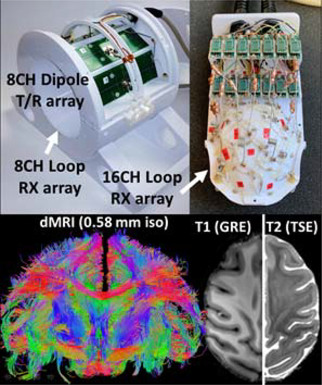
Described is a 32-channel receive array for high resolution brain imaging of Rhesus Macaques at 10.5T. The coil is composed of an 8-channel transmit/receive dipole array, a close-fitting 16-channel loop receive array head cap, and an 8-channel loop receive array located under the chin. This coil system is capable of anatomical and diffusion imaging at down to 0.5 mm isotropic resolution with a three times reduction in sampling time.
Introduction
In recent years, there has been a proliferation of ultra-high field (UHF) systems (defined as 7 tesla (T) and higher) for human imaging, primarily motivated by the fact that intrinsic gains in signal-to-noise ratio (SNR) and, in many cases, contrast-to-noise ratio with increasing field strength will permit the acquisition of anatomical, functional and connectivity information with higher spatial and temporal resolutions. This in turn allows better characterization of the functional architectures and the underlying cognitive processes in the brain. Naturally, UHF systems capable of imaging humans have enormous appeal to the vast neuroscience community including the study of non-human primates (NHP).1–4 However, the ability to realize the gains that come with UHF is predicated on the availability of optimized radiofrequency (RF) coils.5–9 At clinical field strengths (1.5T and 3T), optimized RF coils tend to be receive-only array designs which utilize a large behind the bore liner RF body coil for excitation; whereas at UHF, body transmit RF coils are not typically used and thus local transmit and receive coil array designs are needed. Similar to human head imaging at UHF, a combination of transmitter arrays with receiver arrays are desirable for whole head primate applications since they can address transmit inhomogeneity issues at UHF and optimal SNR simultaneously. Gilbert et al.5 followed this path and presented a compact 8-channel (CH) transmit, 24-CH receive array for 7T primate imaging within a head gradient coil designed for human head imaging. In previous work10 we described the development of a 16-CH decoupled transmission line transceiver with 6-CH loop receiver for imaging the brain of NHPs at 7T. This design proved successful due to the SNR benefits of a close-fitting loop receive-only array in combination with a “transceiver” array, constructed of stripline elements that operated both for transmission and reception. This is an appealing concept since the unique field sensitivity profiles of the striplines contributed both to improved parallel imaging performance and supported whole head coverage. The transceiver concept that utilized the stripline array during transmission and reception (no active transmitter detuning), was achievable since the striplines can be positioned to be decoupled from the loop elements of the receive array.
In this paper, we present the development of an NHP coil for 10.5T (447 MHz), the highest magnetic field system that has recently become available for human or large animal imaging11. We extend the concept of using combined transceiver and receive only arrays in this case utilizing dipole transceivers combined with 8, 16 and 24 channel classical loop receivers. There are several benefits to using dipole elements at this high magnetic field compared to stripline elements. Advantages of dipole arrays have been demonstrated at 7T and 10.5T for imaging the human abdomen and head.12,13 Other works have demonstrated the advantages of a loop-dipole combination.14,15 In this work, we utilize an 8-CH transceiver dipole array together with an 8-CH and a 16-CH loop receive only arrays for an effective 8-CH transmit and 32-CH receive coil. A combination of transceiver dipoles with receive loop arrays increases the number of decoupled receiver channels and is expected to optimize penetration and SNR for obtaining high resolutions of deep and sub-cortical structures. The aim of the study was to build and evaluate this combination of transmit and receive arrays for NHP applications.
Methods
Coil housings were designed in-house using Blender 2.79 (Blender Foundation, Amsterdam, Netherlands) and SolidWorks (Dassault Systèmes, Vélizy-Villacoublay, France) and fabricated from polyethylene terephthalate glycol-modified (PETG) filament on an F400 fused deposition modeling (FDM) 3D printer (Fusion3, Greensboro, NC, USA).
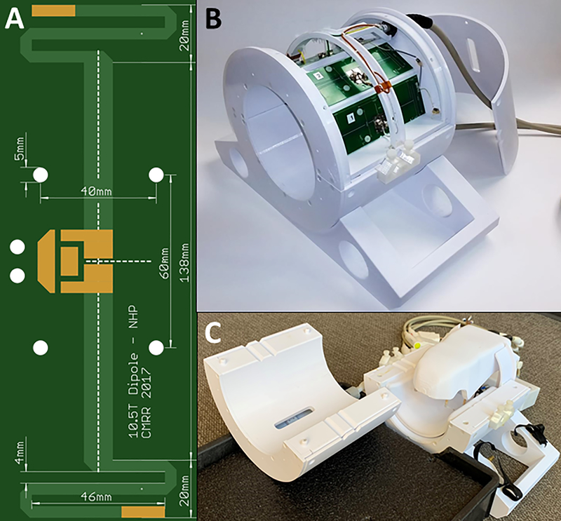
A cylindrical coil former (19 cm ID), split into two pieces along the central axis, accommodates eight 18 cm long end-loaded dipole antennas and features integrated ear bars to allow for consistent positioning of NHPs and a carry tray to simplify the transition of the experimental setup and NHP from the procedure room to the magnet room (Fig. 1). The end-loaded dipole antenna was designed and optimized via electromagnetic simulations in XFdtd 7.5 (Remcom, State College, PA, USA) to be self-resonant at 447 MHz when loaded with a 10 cm diameter spherical phantom (relative permittivity of 56.6 and conductivity of 0.757 S/m) at a distance from the antenna of 9.5 cm (to the phantom center). The dipole was fabricated on standard FR4 PCB by a commercial board house (Advanced Circuits, Maple Grove, MN, USA). Dipole coupling in the 8-CH array was minimized through careful coaxial cable management and sheath current suppression, but no decoupling circuitry was implemented. Each dipole was impedance matched to 50 ohms via a lattice balun16 at the feed point. This dipole array is used for both transmit and receive and is therefore interfaced to the system via an 8-channel (8-CH) T/R switch box which contains modular, field-replaceable T/R switch modules with integrated preamplifiers with a gain of 20 dB and noise figure of 1.0 dB. For the NHP data presented in this paper, the eight channels of this dipole array are excited with equal amplitude and relative phase offsets between neighboring channels of 45° (0°, 45°, 90°, 135°, 180°, 225°, 270°, and 315°) which produce an excitation similar to circular polarization (CP). For this, a single 8 kW RF power amplifier drives the array via a non-magnetic high power 8-way divider (Werlatone Inc., Patterson, NY, USA) which is located at the T/R switch box.
Figure 1:
(A) Photo of the self-resonant end-loaded dipole antenna used as an element in the (B) 8-CH dipole T/R array. The top cover is removed to display the top four dipole elements. (C) The complete coil assembly with receive arrays mounted inside the dipole transceiver which in turn is mounted to a carry tray/bed. The two-halves of the splittable transceiver dipole array is shown separated from each other.
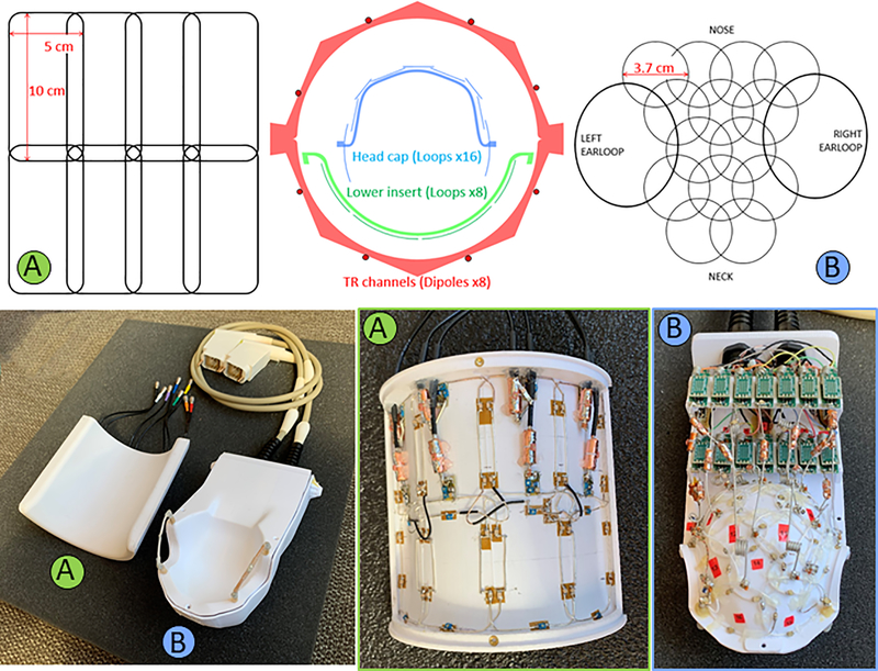
The 8-CH dipole transceiver is combined with two receive array inserts (Fig. 2): an 8-CH loop array lower cylindrical insert and 16-CH loop array constructed on a close-fitting head cap or helmet. The lower insert loops are rectangular 5 × 10 cm2 and arranged into 2 rows of 4 loops each (Figure 2 top-left) mounted on a 14.5 cm diameter cylindrical surface. The individual loops were constructed from 18 AWG (~1.0 mm diameter) silver-coated copper wire and segmented with capacitors in six locations. Specifically, a combination of 2.7 and 3.3 pF ceramic multilayer capacitors (100B series, ATC, Huntington Station, NY, USA) and variable capacitors (SGC3 series, Sprague-Goodman, Westbury, NY, USA) located at the feed point as well as opposite the feed point are used for segmentation, tuning, and matching the loop. The preamps are located in an 8-CH receive box and the interconnection is made using a set of eight ¾ wavelength G_02232–09 (Huber+Suhner, Herisau, Switzerland) coaxial cables connectorized with QMA plugs (Huber+Suhner).
Figure 2:
Axial cross-sectional diagram (top-center) of the coil arrangement for the dipole transmit/receive (TR array), 8-CH receive lower insert (A) and 16-CH receive headcap (B). Loop arrangements for the receive arrays are shown for the headcap (top-left) and lower insert (top-right). Also shown are housing and coils (bottom) for the lower insert (A) and headcap (B). One can also see the preamplifier boards arranged in two rows behind the head cap (bottom-right).
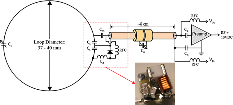
The conformal housing of the head cap receive array was 3D modeled based off CT scan data of an adult female rhesus macaque (Age: 10 years, weight: 6 kg). The housing has accommodations for sixteen preamplifier boards in two banks and a plate through which two cable bundles (each carrying 8 receive signals and 8 PIN diode lines) insert. Receive loops were constructed from 20 AWG (~0.8 mm diameter) silver-coated copper wire and insulated with PTFE shrink tubing. The loops ranged from 37 to 40 mm in diameter and were arranged in rows of 4–3-2–3-2 loops with an ear loop at each end as shown in Figure 2 (top-right). Each loop has 2 to 4 segmenting capacitors with a value of 4.7 pF 0603 size SMDs (Knowles-Syfer, Norwich, UK) mounted on 0.8 mm thick FR4 PCB to provide mechanical support at these locations. A variable capacitor (9702 series Thin-Trim, Johanson Technology, Camarillo, CA, USA) is located opposite from the feed point for tuning the loop. The feed point consists of three 0603 SMD fixed capacitors, an 0807 size air-core inductor (CoilCraft, Cary, IL, USA), and PIN diode (MA4P1250NM-1072T, MACOM, Lowell, MA, USA) all mounted on 0.8mm thick FR4 PCB 5 × 5 mm2 in size. The full schematic is shown in Figure 3. Loops were overlapped to achieve geometric decoupling from nearest neighbors and were actively detuned during transmission to prevent harmful interactions with the transmit field.
Figure 3:
Schematic diagram of receive array channels including loop, feed point, and preamplifier. Inset: 5 × 5 mm feed board with 0603 SMT capacitors, 0807 air core inductor, and 1072T package PIN diode.
Each ear is encircled by a large receive loop which can be partially detached via a pair of non-magnetic, gold plated connectors (ODU, Mühldorf, Germany). This simplifies coil setup on an animal that has its head fixed in ear bars. Half of each ear loop is similar in construction to the rest of the 14 receive loops, however the detachable portions of the ear loops were constructed from flexible 3 mm diameter coaxial cable (only the shield is used as a conductor). Three segmenting capacitors are integrated into the detachable section and protected from mechanical stresses through a combination of the 0.8 mm thick FR4 PCB capacitor footprints and several layers of shrink tubing.
Each loop is connected to a low input impedance preamplifier via 80 mm of 1.2 mm (47 mil) diameter low loss semi-rigid coaxial cable (UT-47-C-TP-LL, Carlisle IT, USA). The length is fine-tuned for each channel to achieve the desired impedance transformation necessary for preamp decoupling. For loops located further than 80 mm from the preamp bank, slightly longer interconnecting cables are used. To compensate for the incorrect phase transformation of the longer cable, a simple phase shifter is implemented at the preamp input consisting of a single series variable capacitor. This cancels the additional phase accumulation of the slightly longer cable. For the loops furthest from the preamp bank, ¾ wavelength cables (~24 cm) were used. These are longer than necessary to make the interconnection so excess length was coiled up.
Capacitor shortened bazooka balun cable traps17 were constructed along the length of each receive array coaxial cable to eliminate sheath currents that are induced by the dipole transmitter. Traps have a single trimmer capacitor across a gap located in the center of the cable trap. To tune these traps on the bench, a half-wave dipole antenna was placed in proximity and parallel to the loop coaxial cable for the channel in question and the cable trap trimmer is adjusted to minimize a through (S21) S-parameter measurement made from the dipole to the preamp output. The preamplifier used is a WMA447A (WanTcom, Minneapolis, MN, USA) which was custom specified for 10.5T MRI. The preamp has 1.5 ohm input impedance, 0.45 dB noise figure, and a 28 dB gain. It is powered via the standard, system provided 10 V through the RF coaxial receive line and a bias tee. The preamp is mounted to a breakout/daughter board, which is mounted inverted to a motherboard. Both boards have an RF ground plane which the preamp is sandwiched between with the intent of providing RF shielding to the preamp from the transmit array.
The preamp motherboard is 4 × 1.3 cm2 in size. It contains an output cable trap and bias tee which couples the PIN diode detune signal onto the loop coax. The daughterboard and motherboard connect via a pair of 3-pin low profile headers and receptacles (BBL-103-G-E and SL-103-G-10, Samtec Inc., New Albany, IN, USA). The center pin carries the RF signal while the two endpins are RF ground.
Coil tune, detune, and coupling was evaluated on the bench using a 16-port VNA (ZNBT8, Rohde&Schwarz, Munich, Germany). Quality (Q) factors were measured with a decoupled B-field double probe. Loop Q-ratio was determined by measuring the Q of the loop both without a load and when loaded with a phantom which provides a similar load as an NHP head. The dipole element Q-ratio is evaluated as the Q-factor of the dipole when loaded with a flat copper sheet (highly conductive sample surrogate, or HCSS) over the Q-ratio when loaded with the sample.18
After measurement on the bench, the coil was then characterized on a 10.5T MRI system composed of an Agilent magnet (88 cm bore diameter, 60 cm open bore) interfaced to Siemens MAGNETOM (Erlangen, Germany) electronics. The system is fitted with whole-body gradients (Siemens SC-72) capable of 70 mT/m amplitude, 200 T/m/s slew rate, and 2nd and 3rd order shims (20A/channel). Transmit (B1+) field maps were calculated from a 3D actual flip-angle imaging (AFI) sequence.19 Noise correlation of the receive elements20 was calculated from a noise scan (zero RF excitation power). The noise scan, in combination with a proton-density-weighted gradient-echo (GE) image and the B1+ map, were used to calculate intrinsic SNR (iSNR) maps. Parallel imaging performance was assessed as the 1/g-factor calculated with the deterministic quantitative GRAPPA approach21,22 using sensitivities calculated with ESPIRIT,23 and noise-correlation determined from noise-only data.
Ten rhesus macaque monkeys (macaca mulatta) were scanned with the proposed coil. All animal procedures were approved by the Institutional Animal Care and Use Committee of the University of Minnesota and complied with United States Public Health Service policy on the humane care and use of laboratory animals.
Monkeys receive ketamine 10mg/kg, midazolam 0.25mg/kg, and atropine 0.04mg/kg IM and were intubated and maintained on isoflurane (1–3%, inhalation) during the scan. The animal was wrapped in warm packs to maintain body temperature. A circulating water bath is used to provide additional heat. A ventilator is used to prevent atelectasis of the lungs, and to regulate CO2 levels. The animal is observed continuously and vital signs and depth of anesthesia are monitored and recorded at 15-min intervals. Rectal temperature (~99.6F), respiration (10–15 breaths/min), end-tidal CO2 (25–40), electrocardiogram (70–150 bpm) and oxygen saturation (>90%) were monitored using an MRI compatible monitor (IRADIMED 3880 MRI Monitor, USA).
Acquisition parameters:
T1w images and T2w images were acquired with a 3D-MPRAGE sequence with left/right (LR) phase-encoding and a 2D turbo spin echo sequence with anterior/posterior (AP) phase-encoding, respectively.
T1w: field-of-view (FOV): 131 × 150 mm2; matrix size of 280 × 320 (0.5 mm isotropic resolution); TR/TE of 3500/3.56 ms.
T2w: FOV: 112 × 150 mm2; matrix size of 288 × 384 (resolution of 0.4 × 0.4 × 1 mm3); TR/TE of 8000/68 ms; flip angle of 120°.
Diffusion-weighted imaging consisted of a single refocused 2D single-shot spin echo (SE) echo planar imaging (EPI) sequence24 using a FOV of 150.8 × 83.52 × 43.5 mm3, matrix size of 260 × 144 × 75 (0.58 mm isotropic resolution), TR/TE of 8270/78.4 ms, flip angle of 90°, BW of 1860 Hz/pixel, and an AP phase-encoding undersampling factor of R=3 (iPAT). Diffusion-weighted images (b-value = 1500 s/mm2) were collected (with diffusion gradients applied along 115 uniformly distributed directions following Caruyer.25
For functional MRI (fMRI), we acquired 0.75 mm isotropic resolution images using a single shot GE-EPI acquisition with R×MB=3×2, with a TE/TR=17.6/1100ms with a total of 58 slices, FOV: 81×116×44mm3 (108×154×58).
Results and Discussion
The eight channels of the dipole transceiver were tuned and matched such that the return loss is < −12 dB in both transmit and receive mode. Nearest neighbor coupling averages −12.3 dB (highest coupling of −10.2 dB). Coupling is largely impacted by cable routing and cable balun tuning and location. The dipole receive preamp input impedance is 50 ohms so this array did not benefit from preamp decoupling. The dipole Q-ratio (QHCSS/Qloaded) is 126/10.18
The 37 mm loops in the headcap receive array are typically tuned and matched to ~ −12 dB with the poorest match being up to −8 dB. This is due both to the use of fixed value ceramic capacitors for matching and the strong dependence on the sample loading the coil. Typical nearest-neighbor coupling is −13.2 dB while next nearest neighbor coupling for in-row loops is −11.4 dB and cross-row loops (which are in closer proximity) is as high as −7.1 dB. Preamp decoupling decreases coupling by 15.6 dB on average. Q-ratios (Qunloaded/Qloaded) range from 280/36 to 300/27.
The lower insert receive array coils are tuned and matched to −13 dB on average. All coupling coefficients are < −11 dB. Preamp decoupling reduces coupling by 16.6 dB on average. Q-ratios range from 146/46 to 170/22.
The highest coupling between the dipole array and loop arrays occurs between the lower half of the dipole array and the lower insert receive array. The most strongly coupled dipole and loop are those that are not geometrically decoupled but still in close proximity. The highest coupling is −10 dB without preamp decoupling and −23 dB with preamp decoupling.
Loop detune performance, as measured with a shielded B-field probe, is typically 20 dB for both the headcap and lower insert arrays. All coupling coefficients from the transmit to detuned receive channels is < −39 dB to ensure protection of receive electronics. The combined mode maximum RF power amplifier (RFPA) output is 69 dBm (8 kW) while the maximum RF transmit power available at the coil is limited by cable attenuation to 64 dBm. The maximum RF input the preamp can tolerate is 30 dBm.
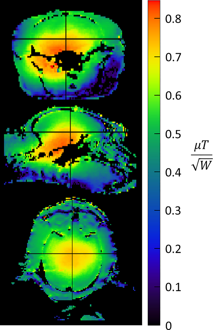
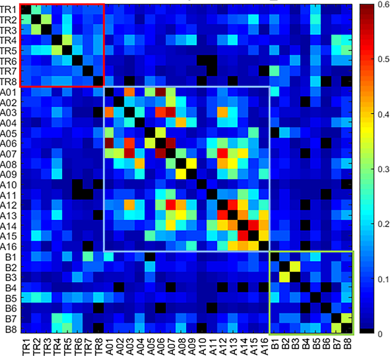
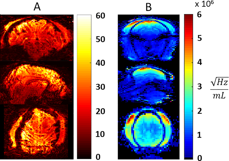
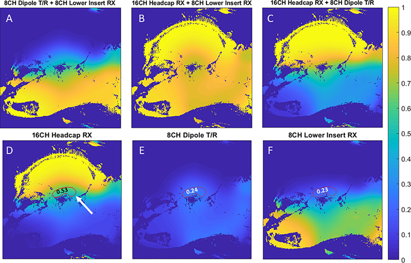
The CP-like transmitter excitation produces the expected B1+ field distribution inside the NHP head with a peak of 0.8 μT/ at the base of the brain with a drop off to ~ 0.4 μT/ in the cortex (Figure 4). A peak of 41 μT can be achieved with 2.7 kW of transmit power available at the coil (the RFPA maximum output is 8 kW and attenuation between the RFPA and coil is 4.7 dB). B1+ homogeneity was sufficient for the application26, however B1+ shimming and parallel transmit (pTx) would be beneficial. Due to problems with the pTx system, which resulted in unacceptable setup times for NHP experiments, subject specific pTx adjustments were not attempted. A noise correlation matrix for all 32 channels (Figure 5) demonstrates low levels of crosstalk (< 0.25) for most channels. A few channels have values as high as 0.6, occurring primarily in the 16-CH head cap. Also shown are temporal SNR (TSNR) maps27 (Figure 6A) and intrinsic SNR (iSNR) maps (Figure 6B). The TSNR for the 0.75mm isotropic acquisition with (R×MB=3×2) is qualitatively on par or larger than previously reported TSNR5 for 1mm isotropic acquisition with (R×MB=2×2), showing that the TSNR can be preserved or improved with less than half the voxel volume. As expected, SNR falls off rapidly as distance from the head cap coils increase, with greatest SNR in the scalp and muscle and up to six-fold lower SNR in deep brain structures. This area of low SNR (Figure 7D, indicated in red), motivated the development of the lower 8-CH receive insert and the use of the dipole array as a transceiver. The lower receive insert and dipole transceiver each contribute approximately ¼ of the overall SNR to the deep brain region outlined in Figure 7D – 7F. These latter two arrays do contribute greatly to signal from outside the brain such as the lower jaw which can be problematic in terms of residual ghosting artifacts in EPI images. This issue was mitigated due to the orientation of the NHP in the magnet bore and the use of confined fields of view for B0 shimming.
Figure 4:
B1+ maps shown in the axial (top), sagittal (center), and coronal (bottom) orientations acquired with a 3D AFI. Maps are scaled in terms of transmit efficiency with units of microtesla per root-watt.
Figure 5:
Noise correlation matrix for all 32 channels which are composed of the dipole transmit/receive channels (TR1 – 8), the 16CH headcap receiver (A01 – 16), and the lower 8CH receiver insert (B1 – 8).
Figure 6:
Temporal SNR of GRE-EPI for 0.75mm isotropic resolution from 700 repetitions, acquired with R×MB=3×2, TE/TR=17.6/1100ms (A) and intrinsic SNR maps (B).
Figure 7:
Relative SNR contribution of various combinations (A,B,C) of the 16CH headcap RX (D), 8CH dipole T/R (E), and 8CH lower insert RX (F). Relative SNR contributions to the ROI drawn in red: 0.53 (16CH heapcap RX), 0.24 (8CH dipole T/R), and 0.23 (8CH lower RX).
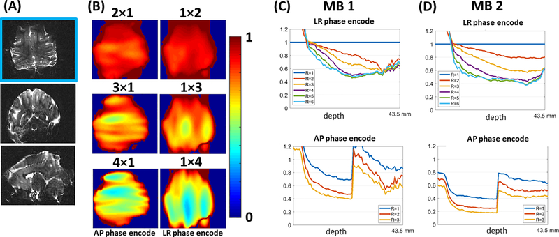
Figure 8 shows an example of the whole brain parallel imaging performance, as 1/g, applicable with a tight FOV for dMRI and fMRI. For multi-slice acquisition of the NHP, only the use of AP or LR phase-encoding direction are necessary to consider. The parallel imaging performance is determined from a single multi-slice three-shot segmented SE-EPI with AP phase-encoding. The 1/g-factor for R=2,3,4 along the LR or the AP direction respectively are shown in 8B, for the axial slice shown in figure 8A. The average noise-amplification for different axial slices is represented by the average 1/g factor for a slice, and plotted in figure 8C for MB=1, with R=2,3,4,5 and 6 along the LR or the AP direction respectively. With the selected 75 slices, the whole brain is covered with a FOV of 44mm. The noise-amplification for MB=2 with R=1,2,3 and using a FOV shift along the phase-encoding of ¼ the FOV between slices are correspondingly plotted in 6D. The mean g-factor for R×MB=3×1 with AP phase-encoding is 1.14±0.1, and the simulations for MB=2, shows that for R=1, the g-factor is larger than 1, in contrast to coils for human imaging where for MB=2 the distributed coil encoding of 32 receiver channels over the FOV enables a g-factor closer to 1. The increase in the average 1/g deeper in the brain correlates spatially to where both the 8 channel Dipole T/R and 8 channel lower insert receiver array contribute to the overall receive sensitivity, as observed from figure 7 D,E and F.
Figure 8:
1/g maps for noise-amplification from parallel imaging calculated using the SE-EPI data. (A) Anatomical images in axial, coronal and sagittal orientations for multi-slice axial SE-EPI used for g-factor calculation from the calculated GRAPPA kernel (B) 1/g maps for R=2,3,4 with phase-encoding undersampling in the L-R and H-F directions calculated using the SE-EPI data corresponding to the axial anatomical images shown in Figure 8A. (C and D) Plots of slice-specific average 1/g value with respect to slice number (stated in terms of depth in millimeters) for R = 1,2,3,4,5,6 (MB 1) and R=1,2,3 (MB 2).
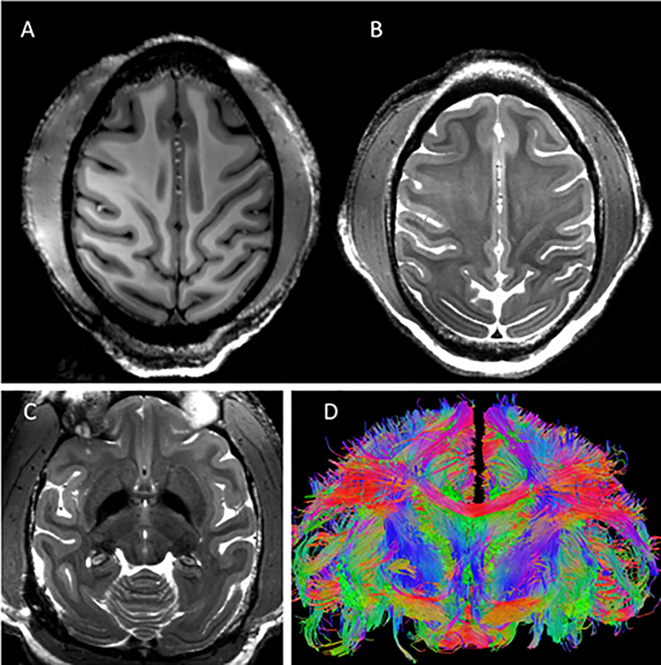
To demonstrate the utility and performance of the coil, ten monkeys were scanned with body weight ranging from 4 kg to 12 kg (6–8 kg was typical). Figure 9 & Figure 10 show representative results from such scans. Excellent T1 and T2 imaging contrast (0.5 mm isotropic and 0.4 × 0.4 × 1.0 mm3, respectively) was achieved at the cortical level with a sharp delineation of the white/gray matter borders (Figure 9A & B) which was maintained at deeper brain areas such as the basal ganglia region (Figure 9C). Excellent whole brain coverage is achieved with the combination of the conformal close-fitting loop arrays (head cap and lower insert) and the dipole transceiver. High-resolution (0.58 mm isotropic) tractography reconstruction of white-matter bundles is shown in Figure 9D.
Figure 9:
Representative results obtained with the developed coil. Excellent imaging contrast was achieved at the cortical level with (A) T1 (0.5mm iso: 131×150 mm2 (280×320), TR/TE=3500/3.56ms) and (B and C) T2 (0.4 × 0.4 × 1.0 mm3: 112×150mm2 (288×384),TR/TE =8000/68ms, FA=120°) weighting at 10.5T with a sharp delineation of the white/gray matter borders in superior slices (A & B) which was maintained at deeper brain areas such as the basal ganglia region (C). High-resolution tractography (0.58 mm iso) reconstruction of white-matter bundles in a coronal slice is shown in (D).
Figure 10:
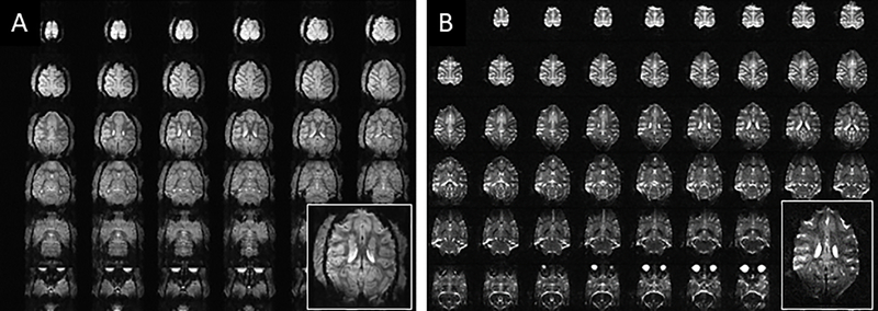
Representative examples of a high-resolution echo-planar imaging (epi) acquired at 10.5T in the NHP model. Gradient-echo (0.75 mm iso: 81 × 116 × 44 mm3 (108×154×58), TR/TE=1100/17.6ms) (A) and spin-echo diffusion (0.58 mm iso: 150.8 × 83.52 × 43.5 mm3 (260×144×75), TR/TE = 8270/78.4ms), (B) acquisition are shown.
Figure 10 shows representative examples of high-resolution echo planar imaging (EPI) acquired at 10.5T in the NHP model. Gradient-echo EPI (for fMRI) and spin-echo EPI (for diffusion acquisitions) with 0.75 mm and 0.58 mm isotropic resolution, respectively, are shown in Figure 10A & B, respectively. Susceptibility artifacts which are evident in these images are due to anatomical air and exacerbated by the high B0 field.
Conclusion
A 32 channel coil system for NHP brain imaging at 10.5T was developed. The coil demonstrated excellent performance and supported submillimeter high resolution imaging at 10.5T of brain anatomy, function, and tractography of fasciculated axonal bundles (obtained through, diffusion imaging (dMRI)). As demonstrated in our earlier work, the ability to combine loop and line elements was found to have numerous advantages and supported higher receive channel counts and parallel imaging gains. In particular, we demonstrated that it is possible to simultaneously receive with an array of close fitting receive loops and an eight dipole array that serves as the transmitter as well. The combined coil supported the higher acceleration factors that were essential for parallel imaging performance to support 0.58 mm isotropic high resolution fMRI and dMRI with three times reduction in sampling. Gains in SNR from inclusion of the transceive array elements during reception were more modest but nevertheless significant in the lower half of the brain and in head areas not covered by the receive loops. Future efforts will focus on using the transmitter in parallel transmit mode on the system which will allow for better B1+ field control as well as further optimize the receive array performance to achieve higher accelerations. One possible direction involves further reducing the size and density of receive loops towards developing a higher channel count receive array for further gains in acceleration.
Acknowledgements
This research is supported by NIH Grants P41 EB027061, NIH U01 EB025144, R01 NS081118, P30 NS076408 and University of Minnesota Udall center P50NS098573.
Abbreviations
- AP
Anterior to Posterior
- AWG
American Wire Gauge
- BW
Bandwidth
- CH
Channel
- CT
Computed Tomography
- dMRI
Diffusion MRI
- EPI
Echo Planar Imaging
- FDM
Fused Deposition Modeling
- fMRI
Functional MRI
- FOV
Field of View
- GE
Gradient-Echo
- IM
Intramuscular
- iPAT
Integrated Parallel Acquisition Techniques
- iSNR
Intrinsic Signal-to-Noise Ratio
- LR
Left to Right
- MB
Multiband
- NHP
Non-Human Primate
- PCB
Printed Circuit Board
- PETG
Polyethylene Terephthalate Glycol-modified
- PTFE
Polytetrafluoroethylene
- pTx
Parallel Transmit
- Q
Quality
- R
Reduction factor
- RF
Radio Frequency
- RFPA
Radio Frequency Power Amplifier
- SE
Spin-Echo
- S
Scattering
- SMD
Surface Mount Device
- SNR
Signal to Noise Ratio
- T
Tesla
- T1w
T1 weighted
- T2w
T2 weighted
- TSNR
Temporal Signal-to-Noise Ratio
- UHF
Ultra High Field
Data Availability Statement
Data available on request from the authors.
References:
- 1.Milham MP, Ai L, Koo B, et al. An Open Resource for Non-human Primate Imaging. Neuron. 2018;100(1):61–74.e2. doi: 10.1016/j.neuron.2018.08.039 [DOI] [PMC free article] [PubMed] [Google Scholar]
- 2.Logothetis NK, Merkle H, Augath M, Trinath T, Uǧurbil K. Ultra high-resolution fMRI in monkeys with implanted RF coils. Neuron. 2002;35(2):227–242. doi: 10.1016/S0896-6273(02)00775-4 [DOI] [PubMed] [Google Scholar]
- 3.Pfeuffer J, Merkle H, Beyerlein M, Steudel T, Logothetis NK. Anatomical and functional MR imaging in the macaque monkey using a vertical large-bore 7 Tesla setup. In: Magnetic Resonance Imaging. Vol 22.; 2004:1343–1359. doi: 10.1016/j.mri.2004.10.004 [DOI] [PubMed] [Google Scholar]
- 4.Goense JBM, Ku SP, Merkle H, Tolias AS, Logothetis NK. fMRI of the temporal lobe of the awake monkey at 7 T. Neuroimage. 2008;39(3):1081–1093. doi: 10.1016/j.neuroimage.2007.09.038 [DOI] [PubMed] [Google Scholar]
- 5.Gilbert KM, Gati JS, Barker K, Everling S, Menon RS. Optimized parallel transmit and receive radiofrequency coil for ultrahigh-field MRI of monkeys. Neuroimage. 2016;125:153–161. doi: 10.1016/j.neuroimage.2015.10.048 [DOI] [PubMed] [Google Scholar]
- 6.Goense J, Logothetis NK, Merkle H. Flexible, phase-matched, linear receive arrays for high-field MRI in monkeys. Magn Reson Imaging. 2010;28(8):1183–1191. doi: 10.1016/j.mri.2010.03.026 [DOI] [PubMed] [Google Scholar]
- 7.Janssens T, Keil B, Farivar R, et al. An implanted 8-channel array coil for high-resolution macaque MRI at 3T. Neuroimage. 2012;62(3):1529–1536. doi: 10.1016/j.neuroimage.2012.05.028 [DOI] [PMC free article] [PubMed] [Google Scholar]
- 8.Janssens T, Keil B, Serano P, et al. A 22-channel receive array with Helmholtz transmit coil for anesthetized macaque MRI at 3 T. NMR Biomed. 2013;26(11):1431–1440. doi: 10.1002/nbm.2970 [DOI] [PubMed] [Google Scholar]
- 9.Gilbert KM, Schaeffer DJ, Zeman P, et al. Concentric radiofrequency arrays to increase the statistical power of resting-state maps in monkeys. Neuroimage. 2018;178:287–294. doi: 10.1016/j.neuroimage.2018.05.057 [DOI] [PubMed] [Google Scholar]
- 10.Adriany G, Harel N, Yacoub E, Moeller S, Ghose G and KU. A 21 channel Transceiver Array for Non-human Primate Applications at 7 tesla. In: Proc. Intl. Soc. Mag. Reson. Med. 18 (2010). Vol 18.; 2010:1490. [Google Scholar]
- 11.He X, Ertürk MA, Grant A, et al. First in-vivo human imaging at 10.5T: Imaging the body at 447 MHz. Magn Reson Med. 2020;84(1):289–303. doi: 10.1002/mrm.28131 [DOI] [PMC free article] [PubMed] [Google Scholar]
- 12.Ertürk MA, Wu X, Eryaman Y, et al. Toward imaging the body at 10.5 tesla. Magn Reson Med. 2017;77(1):434–443. doi: 10.1002/mrm.26487 [DOI] [PMC free article] [PubMed] [Google Scholar]
- 13.Raaijmakers AJE, Italiaander M, Voogt IJ, et al. The fractionated dipole antenna: A new antenna for body imaging at 7 Tesla. Magn Reson Med. 2015;00:1–9. doi: 10.1002/mrm.25596 [DOI] [PubMed] [Google Scholar]
- 14.Ertürk MA, Raaijmakers AJE, Adriany G, Uğurbil K, Metzger GJ. A 16-channel combined loop-dipole transceiver array for 7 Tesla body MRI. Magn Reson Med. 2017;77(2):884–894. doi: 10.1002/mrm.26153 [DOI] [PMC free article] [PubMed] [Google Scholar]
- 15.Woo MK, Lagore RL, Delabarre L, et al. A 16-channel transceiver loop+dipole antennas head array for human head imaging at 10.5T. Proc 2017 19th Int Conf Electromagn Adv Appl ICEAA 2017. 2017:1649–1652. doi: 10.1109/ICEAA.2017.8065607 [DOI] [Google Scholar]
- 16.Frankel S Reactance Networks for Coupling Between Unbalanced and Balanced Circuits. Proc IRE. 1941;29(9):486–493. doi: 10.1109/JRPROC.1941.231668 [DOI] [Google Scholar]
- 17.Peterson DM, Beck BL, Duensing GR. Reduction of Cable Shield Currents Generated by High Field Body Coils at 3 Tesla and Above. In: Proc. Intl. Soc. Mag. Reson. Med. 10 (2002). Vol 10.; 2002:850. [Google Scholar]
- 18.Chen G, Collins CM, Sodickson DK, Wiggins GC. A method to assess the loss of a dipole antenna for ultra-high-field MRI. Magn Reson Med. 2018;79(3):1773–1780. doi: 10.1002/mrm.26777 [DOI] [PMC free article] [PubMed] [Google Scholar]
- 19.Yarnykh VL. Actual flip-angle imaging in the pulsed steady state: a method for rapid three-dimensional mapping of the transmitted radiofrequency field. Magn Reson Med. 2007;57(1):192–200. doi: 10.1002/mrm.21120 [DOI] [PubMed] [Google Scholar]
- 20.Roemer PB, Edelstein W a, Hayes CE, Souza SP, Mueller OM. The NMR phased array. Magn Reson Med. 1990;16(2):192–225. http://www.ncbi.nlm.nih.gov/pubmed/2266841. [DOI] [PubMed] [Google Scholar]
- 21.Breuer FA, Kannengiesser SAR, Blaimer M, Seiberlich N, Jakob PM, Griswold MA. General formulation for quantitative G-factor calculation in GRAPPA reconstructions. Magn Reson Med. 2009;62(3):739–746. doi: 10.1002/mrm.22066 [DOI] [PubMed] [Google Scholar]
- 22.Griswold MA, Jakob PM, Heidemann RM, et al. Generalized Autocalibrating Partially Parallel Acquisitions (GRAPPA). Magn Reson Med. 2002;47(6):1202–1210. doi: 10.1002/mrm.10171 [DOI] [PubMed] [Google Scholar]
- 23.Uecker M, Lai P, Murphy MJ, et al. ESPIRiT-an eigenvalue approach to autocalibrating parallel MRI: Where SENSE meets GRAPPA. Magn Reson Med. 2014;71(3):990–1001. doi: 10.1002/mrm.24751 [DOI] [PMC free article] [PubMed] [Google Scholar]
- 24.Stejskal EO, Tanner JE. Spin diffusion measurements: Spin echoes in the presence of a time-dependent field gradient. J Chem Phys. 1965;42(1):288–292. doi: 10.1063/1.1695690 [DOI] [Google Scholar]
- 25.Caruyer E, Lenglet C, Sapiro G, Deriche R. Design of multishell sampling schemes with uniform coverage in diffusion MRI. Magn Reson Med. 2013;69(6):1534–1540. doi: 10.1002/mrm.24736 [DOI] [PMC free article] [PubMed] [Google Scholar]
- 26.Yacoub E, Grier MD, Auerbach EJ, et al. Ultra-high field (10.5 T) resting state fMRI in the macaque. Neuroimage. 2020;223:117349. doi: 10.1016/j.neuroimage.2020.117349 [DOI] [PMC free article] [PubMed] [Google Scholar]
- 27.Triantafyllou C, Polimeni JR, Keil B, Wald LL. Coil-to-coil physiological noise correlations and their impact on functional MRI time-series signal-to-noise ratio. Magn Reson Med. 2016;76(6):1708–1719. doi: 10.1002/mrm.26041 [DOI] [PMC free article] [PubMed] [Google Scholar]
Associated Data
This section collects any data citations, data availability statements, or supplementary materials included in this article.
Data Availability Statement
Data available on request from the authors.


