Abstract
Airborne transmissions of infectious disease (e.g. SARS-CoV-2) in indoor environments may induce serious threat to public health. Air purification devices are necessary to remove and/or inactivate airborne biological species from indoor air environment. Corona discharge in an electrostatic precipitator is capable of removing particulate matter and disinfecting biological aerosols to act as electrostatic disinfector (ESD). The ions generated by ESD can effectively inactivate bacteria/viruses. However, the available research rarely investigated disinfection effect of ESD, and it is urgent to develop quantitative ESD design methods for building mechanical ventilation applications. This study developed an integrated numerical model to simulate disinfection performance of ESD. The numerical model considers the ionized electric field, electrohydrodynamic flow, and biological disinfection. The model prediction was validated with the experimental data (E. coli): Good agreement was observed. The validated model then was used to study the influences of essential design parameters (e.g. voltage, inlet velocity) of ESD on disinfection efficiency. The effects of modeling of electrophoretic force and EHD (electrohydrodynamic) flow patterns on disinfection efficiency and computing time were also analyzed. The disinfection efficiency of well-designed ESD (with space charge density of 3.6 × 10−06 C/m3) could be as high as 100%. Compared with HEPA, ESD could save 99% of energy consumed by HEPA without sacrificing disinfection efficiency.
Keywords: Airborne disinfection, Ion disinfection, Energy saving, Airborne SARS-CoV-2
1. Introduction
Airborne transmissions of infectious disease in indoor environment may induce serious threat to public health [[1], [2]]. For example, the outbreaks of corona-virus disease 2019 (COVID-19) have yet caused immeasurable losses to the whole world [[3], [4], [5], [6], [7]]. Aerosol transmission of SARS-CoV-2 (severe acute respiratory syndrome corona-virus 2) pathogens has been proven as an important pathway [8]). Recent studies have shown that there is a potential infection risk of airborne transmission of diseases in poorly ventilated indoor environments [[9], [10], [11], [12]]. In order to control airborne transmission of diseases in indoor environment, developments of advanced and energy efficient air cleaning devices are urgently needed [8]. The system must be efficient in term of purification and energy, and does not generate any by-products [13,14]. In respect of the health associations of airborne biological species, there is a huge demand for high-efficient disinfection/purification technologies for indoor environment application [8,15,16].
Air purification system has been recognized to be an effective approach in indoor air pollutant control [17,18]. The widely used air cleaning types include fibrous particulate matter filter, gaseous adsorption filter, photo-catalytic device and ESP (electrostatic precipitator) [[19], [20], [21], [22]]. For the removal of particles or biological aerosols, fibrous filter (e.g. High efficiency particulate air filter, HEPA) has been widely utilized and proven to be very effective. When filtration efficiency is close to 100%, the pressure drop and energy consumption of fibrous filter is very high [23,24], which limits its engineering applications. In order to overcome the disadvantage of fibrous filter, ESP and electrostatic assisted air filter draws more and more attentions [23,24].
A typical air purification method such as ESP has double functions: physical removal and biological disinfection [25]. In ESP, particles are charged in ionized electric field and move to collection plates driven by Coulomb force, which is so-called physical removal mechanism [26]. Besides, the ions generated by corona discharge would inactivate bacteria and other microorganisms [27]. Earlier experimental work reported that airborne biological aerosols can be effectively disinfected when they are exposed to surrounding ions [15,27,28]. When ESP is designed to control biological pollutant, it is called ESD (Electrostatic disinfector), as show in Fig. 1 . As opposed to commercial ion emitter [27], ESD generates higher ion concentration, which may result in higher disinfection efficiency. Numerous studies develop ESP design/optimization methods toward particle removal and dust precipitation [26]. However, the disinfection effects of ESD are rarely considered in the current literature, and relevant quantitative design method is lacking. The differences between ESP and ESD simulations/designs include usage aim and physical field. The ESD inactivates the biological aerosol rather than removing them (Fig. 1). For common particulate matter removal, the aim of ESP is to efficiently capture particles onto collection plates [26]. developed ESP model to simulate ionized electric field, particle charging, motion and removal. For ESD modeling, the biological disinfection model should be incorporated with the available ESP model (including electric field and particle motion/capture). If biological disinfection effects are not considered in ESD design and biological aerosols are regarded as common particles, the overall performance of ESD will be underestimated, resulting in lower designed airflow rate and higher energy consumption. Therefore, it is necessary to develop an integrated numerical model (including corona discharge, turbulent air flow and biological particle concentration) to predict the disinfection performance of ESD reliably and accurately.
Fig. 1.
Utilizing electrostatic disinfector (ESD) to inactivate airborne bacteria/virus in indoor environments.
This current study proposed a numerical method to simulate disinfection performance of ESD and optimize design parameters. Overall ESD performance were considered, including disinfection efficiency, energy consumption and generation of secondary pollution. Firstly, experimental disinfection efficiency data from published literature was adopted to validate the numerical model. The validated model was then utilized to investigate the influence of critical parameters (e.g. applied voltage, inlet velocity) on disinfection efficiency of a typical ESD configuration with single discharge wire and multiple wires. The effects of EHD (electrohydrodynamic) flow and electrophoretic force on simulation results were also discussed. How to save computing time in ESD simulation was also analyzed. Based on simulation results, an optimal ESD configuration with multiple discharge wires was proposed. Finally, the optimal ESD was compared with the widely used HEPA (High efficiency particulate air filter), based on removal/disinfection efficiency, energy consumption and secondary pollution, to show its overall performances and advantages.
2. Methodology
2.1. Numerical method
This section described numerical model, which was utilized in modeling of ionized electric field, airflow and inactivation of biological species in ESD.
The single specie model was adopted to simulate corona discharge in ESD [29,30]. The main outputs included distributions of electric potential and space charge density (ion concentration). In single specie model, the ionization layer around discharge electrode was neglected, which was quite different from the multiple species corona discharge model [29,31]. The ions with the same polarity as the applied voltage were released from discharge electrode and moved towards grounded plates. Since electric migration velocity of ion was much higher than typical velocity of airflow, the effects of air motion on the ion concentration distribution could be ignored [29]. Equations (1), (2) were used to simulate the electric potential and space charge density, respectively.
| (1) |
| (2) |
where is the electric field intensity vector (V/m), ρ is the space charge density (C/m3), V is the electric potential (V), ε 0 is the air permittivity (F/m), k i is the ion mobility (m2/Vs).
EHD (Electrohydrodynamic) flows were governed by continuity equation (3) and well-known Navier-Stokes equation (4) [31]. The electric body force generated by corona discharge was incorporated into the Navier-Stokes equation, as momentum source term. All the numerical simulations were carried out at steady-state conditions.
| (3) |
| (4) |
where ρ a is the air density (kg/m3), t is the physical time (s), is the air velocity (m/s), is the electric field strength (V/m), ρ is the space charge density (C/m3), p is the pressure (Pa) and μ is the air viscosity (Pa × s). The represents Coulomb force acting as the electric body force for air flow in ESD.
Once the ionized electric field and air flow field were obtained, Equation (5) was used to simulate biological species distribution and disinfection efficiency of ESD [27].
| (5) |
where C i is the activated biological particle number concentration (#/m3), v si is the particle settling velocity (m/s), u is the air velocity (m/s), t is the physical time (s), D is the Brownian diffusion coefficient (m2/s), ε p is the particle eddy diffusivity (m2/s), ρ is the space charge density (C/m3), and A is the disinfection coefficient (susceptibility) due to ion disinfection (m3/(C × s)).
2.2. Case description
Four cases were established in the current study. Case-1&2 were validation cases. Case-3-4 were conducted to investigate the effects of key parameters (e.g. applied voltage, inlet velocity and disinfection coefficient of ESD) on disinfection efficiency. In Case-3&4, single-wire and multiple wires were respectively adopted in ESD design. Then the overall performance of ESD and commonly used HEPA were compared/evaluated, including disinfection efficiency, by-product generation (ozone) and energy consumption. Regarding their geometry characteristics, two dimensional geometries were adopted in all the cases (Case 1–4).
Fig. 2 shows the geometries of two experimental cases (Case-1&2) from literature, which were used for model validation [27]. The dimension of the ventilation duct was 0.2 m × 0.2 m × 5.0 m. The diameter of the ion generator (cylinder shape) was 0.03804 m, and its length was 0.18 m (Y). In Case-1 and Case-2, one and two ion generators were placed in the ventilation duct, respectively. The high voltage device was used to generate ions with high concentration. The ions could react with biological pollutant (e.g. respiratory viruses), resulting in relatively high disinfection efficiency. In experiments/simulations, the inlet air velocity was fixed as 3.5 m/s. Detailed information about related boundary conditions could be find in Ref. [27].
Fig. 2.
The geometries of validation cases: Case-1 with one ion generator, Case-2 with two ion generators.
Detailed information of experimental measurements of Case-1&2 can be found in literature [27], and only brief description was presented in the current study. A modular galvanized steel duct-work system was designed and fabricated. An air ionization equipment (102C, Plasma Air International) was installed in the duct. The pathogens were atomized and aerosolized by a 24-jet nebulizer (Collision Nebulizer, BGI). The Gram-negative bacilli Escherichia coli (E. coli, ATCC 10536) was selected in literature to test the disinfection efficiency of the ion generator. Two single-stage viable Andersen cascade impactors (N6, Thermo Scientific) with compressed air pump were used to sample the airborne microbial concentration. In experiments, the disinfection efficiency (eff) was determined by equation (6), where CFU up and CFU down are the colony forming units of E. coli from up/downstream locations of air cleaner (air ionization equipment). Incubation method was used to determine the CFU values.
| (6) |
In order to investigate the influences of different key parameters (e.g. applied voltage, inlet velocity, disinfection coefficient) on disinfection efficiency, a typical configuration of ESD with single wire with the dimension of 600 mm by 100 mm was adopted, as shown in Fig. 3 [32]. The wires (with cylindrical shape) were adopted in Case-3, and the radius of discharge wire was 0.5 mm. In numerical simulations, the ranges of applied voltage (to wire) and inlet air velocity were 20–29 kV and 1–5 m/s, respectively.
Fig. 3.
The geometries of Case-3: typical ESD with singe-wire to plate configuration.
Case-4 was established to investigate the influences of different design parameters on disinfection efficiency of a typical ESD with multiple discharge wires [20]. Fig. 4 shows that the length and width of ESD was 500 mm and 67 mm, respectively. The wires (with cylindrical shape) were adopted in Case-4, and the radius of discharge wire was 0.1 mm. In numerical simulations, the ranges of applied voltage (to wire) and inlet air velocity were 6.5–8.5 kV and 1–5 m/s, respectively.
Fig. 4.
The geometries of Case-4: typical ESD with multiple-wires to plate configuration.
Table 1 summaries the information of various simulation cases. Cases-1&2 were conducted for model validation. Case-3 was conducted to investigate the influences of key parameters (applied voltage, inlet velocity and disinfection coefficient) on disinfection efficiency of ESD with single wire. The effects of two physical mechanisms were also analyzed: EHD (electrohydrodynamic) flow and electrophoretic effect. Further simulations were then carried to study the impact of wire numbers on the system performance. Finally, the performance of ESD was compared with the performance of widely used HEPA, from the perspectives of disinfection efficiency, energy consumption and secondary pollution generation.
Table 1.
Case summary for the ESD simulations.
| Case. No | ESD pattern | Case purpose |
|---|---|---|
| Case-1&2 | Ion generator | Numerical model validation |
| Case-3 | Single discharge wire | The influences of key parameters (applied voltage, inlet velocity and disinfection coefficient) on disinfection efficiency of ESD |
| The influences of physical mechanisms (EHD flow and electrophoretic force effect) on disinfection efficiency of ESD | ||
| Case-4 | Multiple discharge wires | The influences of key parameters (applied voltage, inlet velocity and disinfection coefficient) on disinfection efficiency of ESD |
In Case 1&2 (validation cases), the Gram-negative bacilli Escherichia coli (ATCC 10536) was selected to test the ion disinfection efficiency [27]. In Case 1&2, the disinfection coefficient “A” (3 × 10⁻¹¹ (m3/(C × s))) value was determined by experimental data and trial-and-error approach [27]. In Case 3&4, the influences of different “A” values on disinfection efficiency was investigated, and its range was (3 × 10⁻¹¹ (m3/(C × s))) to (3 × 10⁻¹⁵ (m3/(C × s))).
2.3. Mesh strategy and boundary conditions
The COMSOL platform was adopted to simulate the multiple physics fields, including corona discharge, turbulent air flow and biological particle concentration. All the numerical cases adopted the same boundary conditions and meshing strategy. For simplicity, Case-3 was selected as an example to illustrate the settings of boundary conditions and mesh distribution, as shown by Fig. 5 . The triangular meshes were used, and total element number was 12416. Mesh independence test was conducted to ensure reliability. Local meshing refinement was used around the discharge wires. The problem of the corona discharge modeling was governed by two partial differential equations with unknown electric potential and space charge density. The boundary conditions for the electric potential were straightforward: a given applied voltage (V P) on the discharge wires (or ion generators) and zero potential on the grounded plates. The Kaptzov hypothesis was used to calculate the boundary value of space charge density over the discharge wires [26]. The boundary conditions for the airflow were also straightforward: two grounded plates and the wire surface acted as stationary walls. The “Velocity Inlet” and “Pressure Outlet” types in COMSOL was respectively adopted for inlet and outlet of the ESD. For biological particle concentration, the dimensional inlet particle concentration (1 × 1004 (#/m3)) was defined in each case, and “Outflow” type was applied for ESD channel outlet. The boundary conditions of “ion generator” in Case-1&2 were the same to those of “discharge wire” in Case-3&4. Table 2 summarizes the boundary condition information in various cases.
Fig. 5.
Boundary conditions and mesh distribution in Case-3.
Table 2.
Boundary conditions for the ESD simulation (VP is applied voltage on discharge wires).
| Electric potential (V) | Airflow field | |
|---|---|---|
| Inlet | Velocity inlet | |
| Outlet | Pressure outlet | |
| Discharge wire | No-slip sidewall | |
| Grounded plate | No-slip sidewall |
3. Results
3.1. Cases-1&2: Model validation
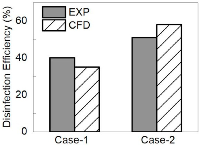
Fig. 6 compares the simulated and experimental disinfection efficiency of ion devices. The disinfection efficiency of Case-2 was higher than that of Case-1, due to more ion generators in ventilation duct. For Case-1, the simulated and experimental efficiency were 35% and 40%, respectively; while for Case-2, the simulated and experimental efficiency were 58% and 51%, respectively. This shows that the relative model discrepancies of Case-1 and Case-2 were 12.5% and 13.7%, respectively. The relative discrepancy was defined as the ratio of difference between simulated and experimental efficiency to the value of experimental efficiency. The results indicate that there was a reasonably good agreement between the model prediction and the experiment. However, some discrepancies between numerical and experimental results can be observed. The discrepancies can be attributed to two aspects: simulation and experiment. Firstly, air turbulence modeling in ESD may bring some errors of disinfection efficiency. Air turbulence significantly influenced airborne biological particle motion and disinfection performance of ESD. However, accurate modeling of air turbulence is quite challenging [33]. Secondly, the experiments of ion disinfection was quite complex, and some measurement uncertainties may exist [27]. Therefore, the errors of air turbulence modeling and experimental measurement may lead to some discrepancies.
Fig. 6.
Comparison of simulated and measured disinfection efficiency of validation cases from previous literature [27], Case-1: one ion generator; Case-2: two generators.
In the validation cases, the disinfection coefficient “A” (as described in Equation (5), so-called susceptibility) was considered as 3 × 10⁻¹¹ (m3/(C × s)). The “A” value depended on microorganism types and other environmental factors (e.g. relative humidity, temperature, etc.). This coefficient cannot be directly predicted or modeled: It was determined by a trial-and-error approach based on experimental efficiency [27]. In the following cases, the influences of disinfection coefficient on disinfection efficiency of ESD were investigated. The range of 3 × 10⁻¹⁵ to 3 × 10⁻¹¹ (m3/(C × s)) was adopted in Cases-3&4.
3.2. Case-3: The influences of design parameters for ESD with single wire
The current study investigated the influences of key parameters (applied voltage, inlet velocity and disinfection coefficient) on disinfection efficiency of ESD. Besides, the effects of EHD flow pattern and electrophoretic force on disinfection efficiency were also analyzed.
3.2.1. The voltage-current (V–I) characteristics
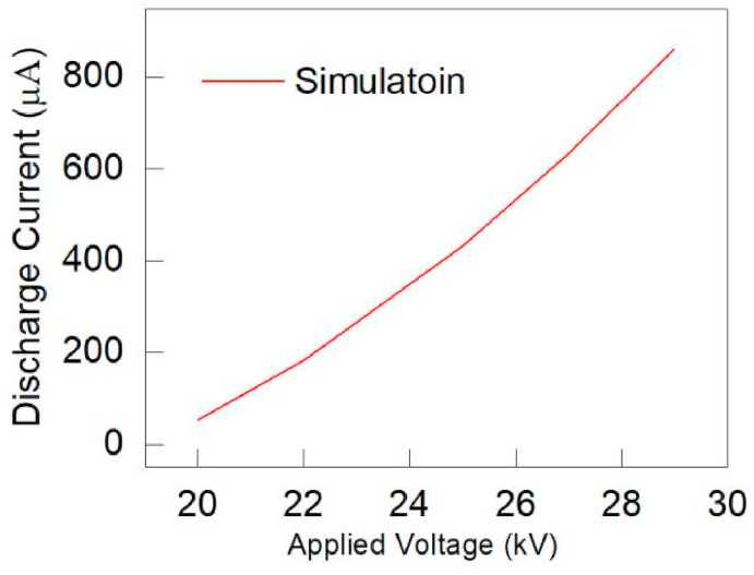
Fig. 7 shows the numerically simulated results of voltage-current (V–I) characteristics in Case-3. Higher applied voltage results in higher discharged current value. In Case-3, the influences of applied voltage (20–29 kV) on disinfection efficiency of ESD were investigated. Therefore, the V–I curve with this wide range of applied voltage was obtained by utilizing numerical simulations.
Fig. 7.
The voltage-current (V–I) relationship of Case-3: numerical results.
3.2.2. The influences of applied voltage and average electric field strength on disinfection efficiency
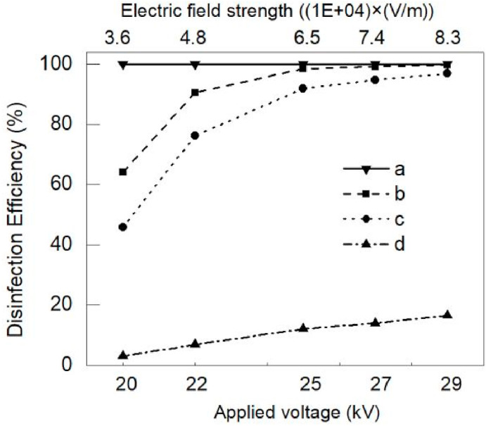
Fig. 8 mainly describes the influences of average electric field strength (ESD domain) and applied voltage on disinfection efficiency of ESD with different inlet velocity and disinfection coefficient (A). If inlet velocity (1 m/s) was relatively low and A value (3 × 10⁻¹¹ (m3/(C × s))) was high enough, disinfection efficiency kept as 100%, as shown in Fig. 8. If A value decreased to 3 × 10⁻¹³ (m3/(C × s)), disinfection efficiency increased with applied voltage. Higher applied voltage generated intenser ionized electric field and higher ion concentration, resulting in increase of disinfection efficiency. If applied voltage was high enough (higher than 28 kV, and lower than breakdown voltage), the disinfection efficiency was close to 100%, as shown in Fig. 8. For extremely low value of A (e.g., 3 × 10⁻¹⁵ (m3/(C × s))), the disinfection efficiency was lower than 20%. Disinfection efficiency of ESD was sensitive to applied voltage and electric field strength. In practical applications, adjustment of applied voltage was an effective way to control disinfection performance.
Fig. 8.
The influences of average electric field strength/applied voltage on disinfection efficiency of ESD with single wire (Case-3): (a) inlet velocity: 1 m/s; disinfection coefficient (A): 3 × 10⁻¹¹ (m3/(C × s)); (b) inlet velocity: 3 m/s; disinfection coefficient (A): 3 × 10⁻¹³ (m3/(C × s)); (c) inlet velocity: 5 m/s; disinfection coefficient (A): 3 × 10⁻¹³ (m3/(C × s)); (d) inlet velocity: 1 m/s; disinfection coefficient (A): 3 × 10⁻¹⁵ (m3/(C × s)).
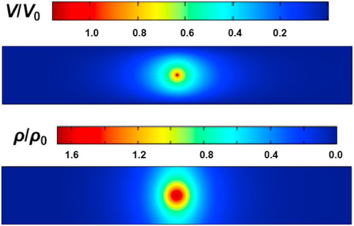
Numerical results of ionized electric field were the base of simulations of air flow and biological disinfection. Fig. 9 shows the spatial distributions of electric potential and space charge density in ESD channel with applied voltage of 29 kV. The dimensionless forms were adopted, and V 0 and ρ 0 were 25 kV and 1.6 × 10−05 C/m3, respectively. Obvious gradients were observed in the region near discharge wire.
Fig. 9.
Simulated distributions of space charge density (ρ) and electric potential (V) in Case-3 with applied voltage of 29 kV.
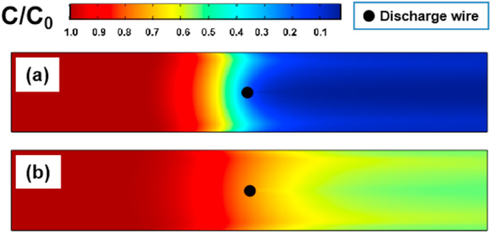
Fig. 10 shows the spatial distributions of biological species concentration in ESD channel. The figure shows for applied voltage of 27 kV, almost all of the biological species were inactivated in the zones upstream of discharge wire. For the spatial zone near discharge wire, disinfection effect and concentration gradient of active biological species was obvious due to higher local ion concentration. The overall disinfection efficiency was close to 100%, as shown in Fig. 10(a). For the ESD with extreme low voltage (20 kV), nearly 40% of the active biological species escaped from the ESD channel, as shown in Fig. 10(b).
Fig. 10.
The influences of applied voltage on active biological species concentrations (Case-3; inlet velocity: 5 m/s; disinfection coefficient (A): 3 × 10⁻¹⁵ (m3/(C × s))): (a) applied voltage: 27 kV; (b) applied voltage: 20 kV.
3.2.3. The influences of inlet velocity on disinfection efficiency
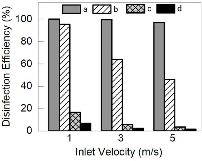
Fig. 11 shows that disinfection efficiency was sensitive to inlet air velocity. The range of inlet air velocity was 1–5 m/s. The disinfection efficiency of ESD was negatively correlated with the inlet air velocity. As the airflow increased, the residence time, ion dose and disinfection efficiency decreased. For the case (applied voltage: 29 kV; A: 3 × 10⁻¹³ (m3/(C × s))) in Fig. 11, ion disinfection efficiency was close to 100% because of high ion concentration. When applied voltage was adjusted to 20 kV, disinfection efficiency of ESD decreased as one may expect. For the case with relatively low value of A (3 × 10⁻¹⁵ (m3/(C × s))), disinfection efficiency was below 20%. If applied voltage and disinfection coefficient were not high enough, disinfection efficiency of ESD obviously varied with inlet velocity/ventilation rate. For the case with the smaller values of applied voltage and disinfection coefficient (applied voltage: 20 kV; disinfection coefficient (A): 3 × 10⁻¹⁵ (m3/(C × s))), the disinfection efficiency of ESD was close to zero. In order to obviously investigate the effects of inlet velocity on disinfection performance, the applied voltage was adjusted to 22 kV, as shown by Fig. 11.
Fig. 11.
The influences of inlet air velocity on disinfection efficiency of ESD with single wire (Case-3): (a) applied voltage: 29 kV; disinfection coefficient (A): 3 × 10⁻¹³ (m3/(C × s)); (b) applied voltage: 20 kV; disinfection coefficient (A): 3 × 10⁻¹³ (m3/(C × s)); (c) applied voltage: 29 kV; disinfection coefficient (A): 3 × 10⁻¹⁵ (m3/(C × s)); (d) applied voltage: 22 kV; disinfection coefficient (A): 3 × 10⁻¹⁵ (m3/(C × s)).
3.2.4. The influences of EHD flow pattern on disinfection efficiency
The current study also investigated the influences of electrohydrodynamic (EHD) flow patterns on the disinfection efficiency of ESD. The electrohydrodynamic (EHD) flow was caused by corona discharge, which is a common phenomenon in air cleaning devices. The physical mechanism of EHD was based on interaction between ions and air molecules. In ESD, ions were generated due to gas ionization and moved to the ground plates driven by Coulomb force. The movement of ions was obstructed by very high frequency collisions with air molecules, resulting in momentum transfer from ions to air molecules. The Coulomb force acting on ions became electric body force on air molecules [34]. The electric body force may significantly modify the airflow pattern and generate EHD flow, as described by Equation (4).
For channel flow without corona discharge, the airflow streamlines were parallel approximately. Once corona discharge occurred, intense turbulence and complex EHD vortexes existed. In ESD, the electric body force may intensify fluid deformation (including stretching, shearing and whirling) and generate EHD vortexes. The electric body force and air inertia jointly determined EHD flow pattern. Higher applied voltage and lower inlet air velocity could generate an intense EHD flow. Fig. 12 shows the EHD flow streamlines in ESD with different inlet velocity magnitudes. When inlet air velocity was higher than 1 m/s, parallel flow streamlines were observed. Air inertia suppressed electric body force, and obvious EHD vortexes were not observed. In order to comprehensively understand the effects of inlet air velocities on EHD flow patterns, inlet air velocity magnitudes were changed to be lower than 1 m/s. When inlet air velocity was 0.5 m/s, only two EHD vortexes near the grounded plates were generated. If inlet air velocity was decreased to 0.2 m/s, four big EHD vortexes were observed in ESD domain. If inlet air velocity was lower than 1 m/s, the effects of electric body force suppressed air inertia, resulting in generation of obvious vortexes in Fig. 12. When inlet air velocity was changed from 0.5 m/s to 0.2 m/s, more EHD vortexes were generated due to that the EHD effect was negatively correlated with inlet air velocity [32].
Fig. 12.
The influences of inlet air velocity magnitudes on EHD flow pattern in ESD: (a) applied voltage: 29 kV; inlet velocity: 5.0 m/s; (b) applied voltage: 29 kV; inlet velocity: 1.0 m/s; (c) applied voltage: 29 kV; inlet velocity: 0.5 m/s; (b) applied voltage: 29 kV; inlet velocity: 0.2 m/s.
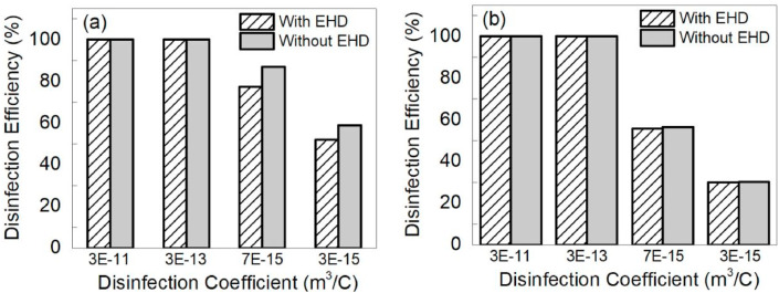
Fig. 13 compares the simulated disinfection efficiency with/without the consideration of EHD flow. For the cases “without EHD”, only electric body force term was removed from Equation (4) and other terms remained the same. The results show that if inlet velocity was 0.2 m/s, the disinfection efficiency discrepancy (with/without EHD) was about 10%. Once inlet velocity was adjusted to 0.5 m/s, the influences of EHD flow on disinfection efficiency could be ignored.
Fig. 13.
The influences of EHD flow pattern on disinfection efficiency of ESD with single wire (Case-3): (a) applied voltage: 29 kV; inlet velocity: 0.2 m/s; (b) applied voltage: 29 kV; inlet velocity: 0.5 m/s.
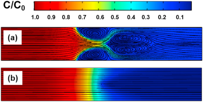
Fig. 14 compares active biological species concentrations for the case with inlet air velocity of 0.2 m/s. Complex EHD flow pattern significantly modified distributions of biological species. When inlet air velocity of ESD device was higher than 1 m/s, the effects of EHD flow on the disinfection performance could be ignored.
Fig. 14.
The influences of EHD flow pattern on biological pollutant concentrations (Case-3; applied voltage: 29 kV; inlet velocity: 0.2 m/s; disinfection coefficient (A): 7 × 10⁻¹⁵ (m3/(C × s))): (a) EHD effect was considered in simulation; (b) EHD effect was not considered in simulation.
3.2.5. The influences of electrophoretic effect on disinfection efficiency
In the previous study focusing on numerical simulation of ion inactivation, the influences of electrophoretic effect on disinfection efficiency were not considered due to high air inertia [27]. In ionized electric field, electric body force acted on charged particles and dragged them move along electric field line. When electric migration velocity (determined by electric body force) was relatively high, electrophoretic effect became one of the dominant factors in disinfection simulation. In ESD channel, air inertia and ionization intensity jointly determined electrophoretic effect. Higher inlet velocity led to higher air inertia in ESD. If inlet air velocity was high enough, charged particles moved along air streamlines and the effect of electric body force could be ignored, as described by Ref. [32]. In order to quantitatively investigate the impacts of electrophoretic effect on disinfection efficiency, Lagrangian model, together with particle charging model and disinfection model, were utilized to model particle dynamics and disinfection in Case-3 [20,27,35].
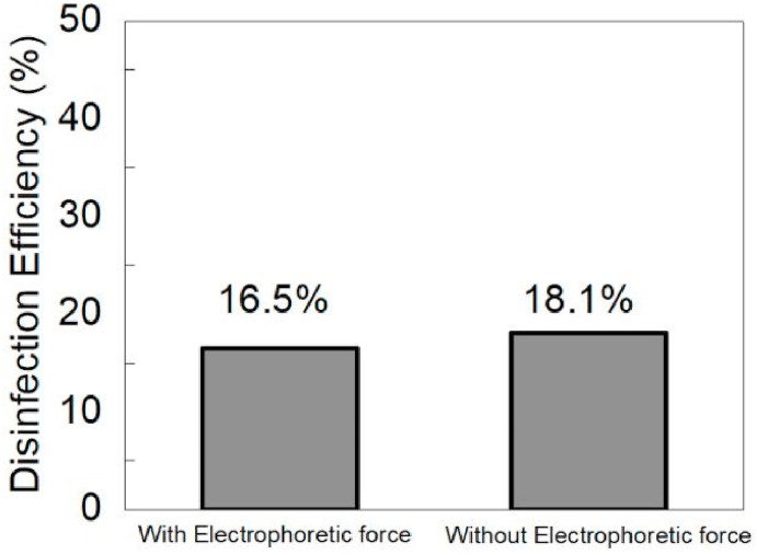
Fig. 15 shows the impacts of electrophoretic effect on disinfection efficiency of ESD with single discharge wire (Case-3, as shown in Fig. 3). The electrophoretic effect in this case was strongest among different cases, because of its highest applied voltage (29 kV) and lowest inlet velocity (1 m/s). If the electrophoretic effect was not considered, disinfection efficiency varied from 16.5% to 18.1%, as shown in Fig. 15. For other cases with higher inlet velocity and lower applied voltage, the discrepancy will become smaller.
Fig. 15.
The influences of electrophoretic effect on disinfection efficiency of ESD with single wire (Case-3), inlet velocity was 1 m/s; applied voltage was 29 kV; disinfection coefficient (A): 3 × 10⁻¹⁵ (m3/(C × s)).
Both of the numerical models developed by the current study and the previous literature [28] were capable of simulating ionized electric field, air flow field, biological particle motion/disinfection. However, in the previous research [28], the electrophoretic force (applied to particles) was ignored, and the EHD effects were not described. In the current study, the electrophoretic force was incorporated into numerical models, and the effects of electrophoretic force and EHD flow pattern on ion disinfection efficiency were considered and well analyzed. Overall, the current study further improves the original model utilized by published literature [28].
3.2.6. Analysis of CFD computing time (Case-3)
One of the main purposes of the current study was to investigate the influences of EHD flow patterns/electrophoretic force on disinfection efficiency of ESD. If the influences of EHD/electrophoretic force are ignorable, the EHD and electrophoretic effects can not be considered in numerical design of ESD, resulting in saving some computing time.
The effects of EHD flow on the disinfection performance could be ignored for ESD cases with relatively higher inlet air velocity (e.g. 1 m/s), as described in “3.2.4 The influences of EHD flow pattern on disinfection efficiency”. Once EHD flow (collision of ion and neutral air) was not considered, electric body force term could be removed from equation (4), resulting in saving approximately 20% of computing time consumed by EHD flow modeling.
Based on the simulation results from literature [32] and analysis of the current study, the electrophoretic effect could be ignored for ESD cases with relatively higher inlet air velocity (e.g. 1 m/s). When the electrophoretic effect was not considered, Eulerian model (Equation (5)) can be directly utilized to simulate biological aerosol motion in ESD. The current research also utilized Lagrangian-based integrated model (Lagrangian model together with particle charging and disinfection models) to simulate ion disinfection processes. Compared with Lagrangian-based integrated model, Eulerian model could save approximately 50% of the computing time (Case-3).
3.3. Case-4: The influences of design parameters for ESD with multiple wires
In Case-3 with typical ESD configuration, a series of simulations were conducted to reveal the quantitative mechanism between some key parameters and disinfection efficiency. In order to further improve ESD performance, an ESD with multiple-wires was proposed based on literature [20].
3.3.1. The voltage-current (V–I) characteristics
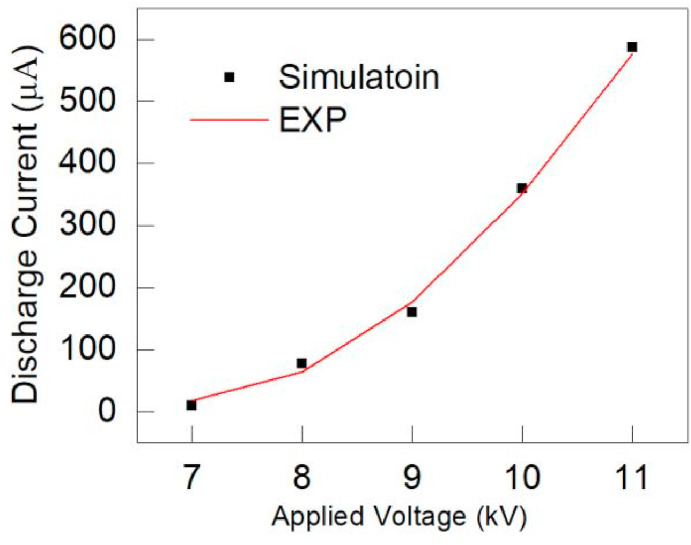
For Case-(1–3), the relevant literature had not provide experimental V–I (voltage-current) relationship curves. For Case-4, the previous study provided experimentally measured V–I characteristics [20]. We utilized numerical models to simulate this V–I curve and obtained agreement between modeled and measured results, as shown in Fig. 16 . The V–I characteristics of ESD was determined by many factors, including electrode characteristics (material, number, shape, and diameter), applied voltage, distance between electrodes et al. [36]. This current study compares discharged current of Case-3 and Case-4 with the similar values of average electric field strength (Case-3: 83 kV/m, (29 kV); Case-4: 107 kV/m, (8.5 kV)). Numerical results indicate that the current value of Case-3 (862 μA) was much higher than that of Case-4 (126 μA), although the average electric field strength of Case-3 was higher.
Fig. 16.
The voltage-current (V–I) relationship of Case-4: numerical and experimental results.
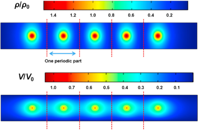
Fig. 17 shows the distributions of dimensionless space charge density and electric potential in ESD channels with multiple wires. The V 0 and ρ 0 were 8 kV and 1.4 × 10−05 (C/m3), respectively. Both V and ρ values decreased from discharge wire to collection plates. Fig. 17 also indicates that spatial distributions of ionized electric field were periodic. For ionized electric field simulations, it was possible to reduce computing cost by conducting numerical simulation of only one periodic part, as described by Fig. 17. In periodic modeling, the boundaries (dotted lines in Fig. 17) between two periodic parts can be regarded as “Zero-Gradient” types [30]. The simulated results of one periodic part can be directly copied to other periodic regions. In future, we will investigate how to properly use periodic modeling to reduce computing time.
Fig. 17.
Simulated distributions of space charge density (ρ) and electric potential (V) in Case-4 with applied voltage of 8.5 kV.
3.3.2. The influences of applied voltage and inlet velocity on disinfection efficiency
Fig. 18 shows the spatial distributions of active biological species concentration in ESD channel with multiple discharge wires. The applied voltage was 6.5 kV, and disinfection coefficient was 3 × 10⁻¹³ (m3/(C × s)). The C 0 in dimensionless form was 1 × 1004 (#/m3). Most of biological species were inactivated before reaching the outlet. Compared to Case-3 with relatively high voltage (e.g. 29 kV), the ESD with multiple discharge wires could still have high disinfection efficiency (close to 100%) with lower applied voltage (e.g. 6.5 kV). Therefore, ESD design configuration with multiple wires was recommended for air disinfection application.
Fig. 18.
Simulated distributions of biological pollutant concentrations (Case-4), inlet velocity: 1 m/s; applied voltage: 6.5 kV; disinfection coefficient (A): 3 × 10⁻¹³ (m3/(C × s)).
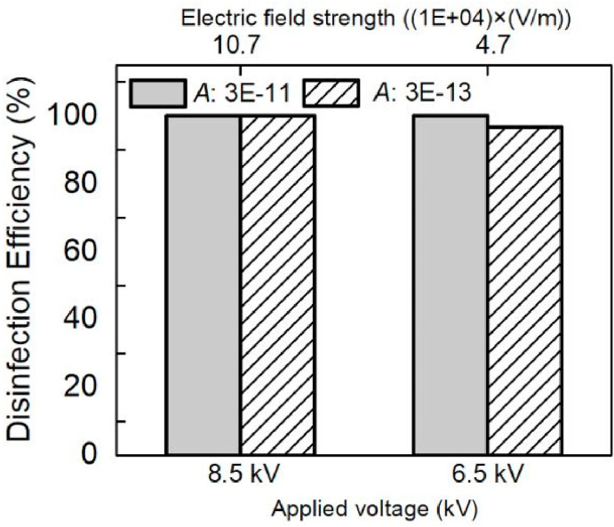
Fig. 19 shows the influences of applied voltage and average electric field strength (ESD domain) on disinfection efficiency of Case-4. If disinfection coefficient “A” was 3 × 10⁻¹¹ (m3/(C × s)), disinfection efficiency was 100% for cases with applied voltage of 6.5/8.5 kV. If the “A” value decreased to 3 × 10⁻¹³ (m3/(C × s)), disinfection efficiency (applied voltage of 6.5 kV) decreased to 96.7%. Similar to the results in Case-3, disinfection performance of ESD were sensitive to applied voltage, electric field strength and disinfection coefficient. In practical operation process, applied voltage was a very effective variable in purification system control. Although the average electric field strength of Case-4 (applied voltage of 6.5 kV) was smaller than those of Case-3 (22–29 kV), its disinfection efficiency was not low (close to 100%). In ESD, ion disinfection efficiency was determined by many factors, including ion concentration, electric field strength, discharge wire shape, biological aerosol type, residence time et al. Therefore, stronger electric field does not necessarily produce high disinfection efficiency.
Fig. 19.
The influences of electric field strength/applied voltage on disinfection efficiency of ESD with multiple wires (Case-4, inlet velocity was 1 m/s).
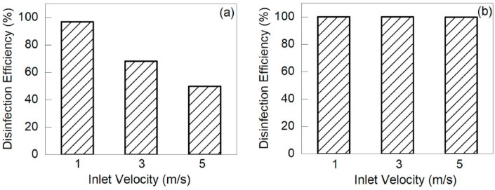
Fig. 20 shows the influences of inlet air velocity on disinfection efficiency of Case-4. When applied voltage was set as 6.5 kV, disinfection efficiency obviously decreased with increase of inlet velocity, which was similar to the results of Case-3. The values of disinfection efficiency varied from 96.74% to 49.66%, as shown in Fig. 20(a). If applied voltage was increased to 8.5 kV, disinfection efficiency was close to 100% (higher than 99%). The values of ion disinfection efficiency (8.5 kV) for inlet velocities of 3 m/s and 5 m/s were 100% and 99.7%, respectively.
Fig. 20.
The influences of inlet air velocity on disinfection efficiency of ESD with multiple discharge wires (Case-4): (a) applied voltage: 6.5 kV, disinfection coefficient (A): 3 × 10⁻¹³ (m3/(C × s)); (b) applied voltage: 8.5 kV, disinfection coefficient (A): 3 × 10⁻¹³ (m3/(C × s)).
3.3.3. Analysis of CFD computing time (Case-4)
For Case-4 with relatively low inlet velocity (1 m/s) and high applied voltage (8.5 kV), the effects of EHD flow and electrophoretic force were relatively stronger. Based on numerical simulations of Case-4 (inlet velocity of 1 m/s, applied voltage of 8.5 kV), the simulated disinfection efficiency discrepancy (with/without EHD and electrophoretic force) was lower than 1% and the effects of these two physical phenomenons were ignorable. Similar to Case-3, the influences of EHD/electrophoretic force can not be considered in Case-4, resulting in saving some computing time (18% of computing time consumed by EHD flow modeling, and 45% of computing time consumed by Lagrangian-based integrated model).
3.3.4. Analysis of ozone generation
The current study also investigated ozone generation of ESD. Equation (7) was used to calculate the differences (ΔC ozone) of ozone concentrations between inlet and outlet of ESD. The key parameter M ozone (ozone generation rate) was determined by applied voltage and discharge current value [37]. The structure of ESD with multiple wires (Case-4) was the same to the devices in our previous study [20], and the experimental results from this literature could be directly utilized to obtain the M ozone value. Table 3 shows the influences of applied voltage and inlet air velocity on ΔC ozone (net ozone concentration) in Case-4. Net ozone concentration was negatively related with inlet air velocity due to the dilution effect. If applied voltage decreased from 8.5 kV to 6.5 kV, ΔC ozone decreased by approximately 40%.
| (7) |
where and are the ozone concentration (ppb) of inlet or outlet of ESD, respectively. Q air is the air flow rate (m3/s), M ozone is the ozone generation rate of ESD (ppb × m3/s).
Table 3.
The influences of applied voltage and inlet air velocity on ΔCozone in Case-4.
| Applied voltage: 6.5 kV | Applied voltage: 8.5 kV | |
|---|---|---|
| Inlet air velocity: 1 m/s | 8.0 ppb | 14.0 ppb |
| Inlet air velocity: 3 m/s | 2.7 ppb | 4.7 ppb |
| Inlet air velocity: 5 m/s | 1.6 ppb | 2.8 ppb |
4. Discussion
4.1. Comparison between optimized ESD and HEPA
In order to illustrate the advantages of ESD with multiple wires, the widely used HEPA was adopted for comparison. The influential design parameters of fibrous pleated filter were mean fiber diameter (d f, μm), mean packing density (α), filter thickness (Z, um). Based on the previous literature [16], the design parameters of HEPA were summarized as follows: (d f: 1.6 μm; α: 0.076; Z: 800 μm). The filtration velocity was 0.06 m/s, and the corresponding pressure drop of HEPA was 343 Pa. The energy consumption of ESD and HEPA was quantitatively evaluated in this section. In comparison, the same operation conditions were adopted: inlet velocity was 1 m/s, air flow rate was 1 m3/s, the targeted section area was 1 m2, and the disinfection coefficient “A” was 3 × 10⁻¹³ (m3/(C × s)). For the calculation of energy consumption of ESD, the high voltage generator and fan (mechanical energy loss) was considered, as shown by equation (8). The simulated results of discharge current value and pressure drop of ESD were utilized to calculated total energy consumption.
| (8) |
where W (W) was the total energy consumption of ESD, W HV (W) and W Fan (W) were respectively energy consumption of high voltage generator and fan, V (V) and I (A) were respectively applied voltage and discharge current value of high voltage generator, P (Pa) and Q (m3/s) were respectively pressure loss and airflow rate value of ESD. For example (V = 6500 (V); I = 0.0005046 (A); P = 0.12 (Pa); Q = 1 (m3/s)), the total energy consumption of ESD was 3.4 (W).
Table 4 compares energy consumption and ozone generation of HEPA and ESD in Case-4. The ESD with applied voltage of 6.5 kV could save 99% of energy consumed by HEPA without sacrificing disinfection efficiency. If applied voltage increased to 8.5 kV, ESD could save 68% of energy consumed by HEPA. Ozone generation in Table 4 means the differences (ΔC ozone, net ozone concentration) of ozone concentrations between inlet and outlet of ESD. Although small amount of ozone was released, the ozone concentrations were lower than the critical values in standards [38]. Overall, one of the most attractive advantages of ESD was energy saving. The disadvantages included ozone generation and larger installation space.
Table 4.
Comparisons of ESD and HEPA based on energy consumption and ozone generation, from the perspectives of airborne disinfection.
| Device Type | ESD (6.5 kV) | ESD (8.5 kV) | HEPA |
|---|---|---|---|
| Energy Consumption (W) | 3.4 | 109.2 | 343 |
| Ozone generation (ppb) | 8 | 14 | 0 |
| Disinfection efficiency (%) | >96.7% | >99.9% | 0 |
| PM removal efficiency (%) | <10% | <10% | >99.9% |
4.2. Comparison between EEAF and HEPA
Our previous study concluded that particle removal efficiency of the ESD with multiple wires (Case-4) was lower than 20% [20]. In order to improve its particle removal efficiency, ESD with five discharge wires were refitted to electrostatic enhanced air filtration system (EEAF). Fig. 21 shows the structure of EEAF, which consists of ESD zone and pleated fibrous filter in series. Charged particles escaping from ESD could be easily captured by pleated fibrous filter medium [20]. In our current study, the ESD zone of EEAF was the same to the design of Case-4 (five discharge wires, applied voltage of 6.5 kV, as shown in Fig. 4). The fibrous filter zone of EEAF was designed based on [39]. The middle-efficient fibrous filter was utilized: average fiber size was 10 μm, solidity ratio was 0.1, filter thickness was 2 mm [39]. External electrostatic field (without ionization) was added across filter medium [40], and electric intensity in filter medium was 1.2 × 10+06 (V/m). Based on the mathematical models from our previous study [39], filter efficiency and energy consumption of EEAF were also simulated and obtained. All of the filtration mechanisms of fibrous filter were considered in the models, including diffusion, interception, impaction and electrostatic force. When inlet air velocity was 1 m/s, filtration efficiency (EEAF, removal efficiency of size-dependent particle number concentration) of particles sizing from 0.1 to 2.5 μm was close to 100%. Table 5 compares energy consumption and ozone generation of EEAF and HEPA. EEAF could save 87.9% of energy consumed by HEPA without sacrificing particle removal efficiency.
Fig. 21.
Geometry of EEAF (electrostatic enhanced air filtration) systems with pleated filter medium, “HV” means high voltage generator.
Table 5.
Comparisons of EEAF and HEPA based on energy consumption and ozone generation, from the perspectives of airborne disinfection and particulate matter (PM) removal.
| Device Type | EEAF (6.5 kV) | EEAF (8.5 kV) | HEPA |
|---|---|---|---|
| Energy Consumption (W) | 41.4 | 147.2 | 343 |
| Ozone generation (ppb) | 8 | 14 | 0 |
| Disinfection efficiency (%) | >96.7% | >99.9% | 0 |
| PM removal efficiency (%) | >99.9% | >99.9% | >99.9% |
4.3. Disinfection performance of ESD towards control of SARS-CoV-2 laden aerosols
ESD proposed in the current study had potential to effectively disinfect and control airborne aerosols containing SARS-CoV-2. However, it was quite difficult to quantitatively evaluate SARS-CoV-2 disinfection performance of ESD system due to lack of relevant experimental data. The key parameter “A” (disinfection coefficient) should be determined by experimental measurements. In the future works, the SARS-CoV-2 disinfection experiments should be conducted to accurately obtain “A” value. Based on the actual “A” value, ESD system could be optimized towards efficient control of SARS-CoV-2. If the “A” value of SARS-CoV-2 aerosols is very low and disinfection efficiency of ESD is not satisfied, the EEAF (as shown in Fig. 21) could be utilized for SARS-CoV-2 control in HVAC (Heating, Ventilation and Air Conditioning) system. The fibrous filter in EEAF can high-efficiently remove SARS-CoV-2 aerosols. Besides, the fibrous filter in EEAF is exposure to continuous ion emissions, and the active biological species deposited on filter can be effectively inactivated by ions [41].
4.4. Determination of inlet velocity of ESD
In the current study, the inlet air velocity of ESD (1–5 m/s) was lower than the limit value of ventilation duct air velocity (8 m/s, for public and residential buildings), which is specified in Chinese standards (GB 50736, 2012) [42]. In engineering applications, inlet air velocity of ESD should be optimized by numerical model, rather than directly determined based on standards/specification. In ESD design, the optimized inlet air velocity magnitude depended on disinfection coefficient (A) and installation space. If the “A” value was low, larger cross section and longer length of ESD were necessary to ensure residence time and disinfection efficiency.
The disinfection efficiency of ESD is very sensitive to inlet air velocity (residence time). For the VAV (Variable Air Volume) air-conditioning system (Du et al., 2016) [43], regulation of ventilation rate may reduce ESD efficiency. The effects of air velocity variation on disinfection efficiency of ESD should be considered in VAV system design.
4.5. Limitations
In order to overcome the disadvantages of traditional air filtration system, ESP and electrostatic assisted air filter draws more and more attentions [44]. Many advanced types of electrostatic assisted air filtration systems were developed [23,24,45], including two-stage ESP, electrostatics assisted metal foam coarse filter, ESP with dielectric coatings et al. The experimental results indicated that these newly developed systems can reduce energy consumption without sacrificing filtration efficiency. These electrostatic assisted air filtration systems may be capable of high-efficiently disinfecting airborne species due to ion generation. It is necessary to evaluate these systems from the perspectives of disinfection efficiency and energy consumption. However, the numerical models developed in the current study could not completely predict the complex multiple physical fields (e.g. foam filter) in these newly developed electrostatic filtration systems. In future, complete experiments will be conducted to evaluate disinfection performance of various electrostatic assisted air filtration systems. Besides, numerical models will be improved to be capable of reasonably/accurately predicting the ion disinfection efficiency of different electrostatic filtration systems.
In ESD, the ions and ozone can simultaneously have disinfection effects on airborne biological aerosols (WS/T 367–2012) [46]. Previous literature [28] and our current study only investigated the ion disinfection, and the ozone disinfection was not considered. In previous literature [28], the measured ozone concentration was relatively low (65 ppb), and the biological disinfection effect of ozone was not taken into consideration. Some standards specified that the effective ozone concentration (from the perspective of airborne disinfection) should be larger than 10 ppm (10000 ppb) (WS/T 367–2012) [46]. For the numerical design method only focusing on ion disinfection, the optimal design pattern of ESD was relatively safe towards engineering application due to that the ozone disinfection effect was ignored. Although the relatively low ozone concentration (such as 65 ppb) may have minor disinfection effect, it is still necessary to investigate the ozone disinfection efficiency of ESD/ion generator. In future, the experimental methods (developed by previous literature [27] should be redesigned to determine the disinfection efficiency/effect of ozone alone. Besides, the new numerical models should be developed to predict ozone generation and ozone disinfection effect in ESD based on the models proposed by our current study and literature [47].
In this current simulation study, the size of biological particle (Escherichia coli, a type of bacteria) was 1 μm, which was described in the published literature [27]. However, some types of bacteria/viruses may be nano-sized. For the nano-particles (particle size is very small, in the nm class), the Brownian force, air drag force (significantly influenced by Cunningham coefficient) and particle charging characteristics are quite different from those of larger particles [48]. Besides, the nano-class particles can be removed from the collection plates of ESD due to variations in drag force, resulting in particle resuspension and secondary-pollution. The phenomenon of resuspension of nano-class particles was also found in indoor environment [49]. Therefore, the effects of particle sizes (from nm class to μm class) on disinfection efficiency of ESD will be investigated in future study.
5. Conclusions
The current study proposed a numerical model to simulate ion disinfection efficiency of airborne biological species in ESD. After validation, numerical model was adopted to investigate the influences of key parameters (applied voltage, inlet velocity and disinfection coefficient) on disinfection efficiency of ESD with single/multiple wires. Then the ESD was compared with traditionally utilized fibrous filter. Based on results, the following conclusions are drawn.
-
•
For ESD, applied voltage, average electric field strength (ESD domain) and inlet velocity had significant influences on disinfection efficiency. Applied voltage was an essential controllable variable in HVAC operations.
-
•
For ESD with relatively high inlet air velocity (e.g. 1 m/s), the influences of electrophoretic force effect and EHD flow pattern on ion disinfection efficiency could be ignored due to high air inertia, resulting in saving some computing time.
-
•
The ESD (applied voltage: 6.5 kV; inlet velocity: 1 m/s; ESD channel length: 0.5 m; ESD channel width: 0.067 m; five wires in ESD channel) could activate 100% of the incoming airborne biological species. Compared with widely used HEPA, the ESD could save 99% of energy consumed by HEPA without sacrificing removal/disinfection efficiency.
-
•
Currently, the disinfection coefficient “A” was determined based on experimental data. In future, it is necessary to develop a method (e.g. mathematical model or database) to calculate the “A” value without preliminary experiments.
Declaration of competing interest
The authors declare that they have no known competing financial interests or personal relationships that could have appeared to influence the work reported in this paper.
Acknowledgements
The authors would like to acknowledge the coordinated support from Natural Science Foundation of China (Grant No. 51808138; Grant No. 51778385), Basic and Applied Basic Research Fund of Guangdong Province (Grant No. 2019A1515011832). Prashant Kumar and Shi-Jie Cao acknowledge the support received via the University of Surrey's awards for the Clear Air Engineering for Homes (CArE-Homes) project under the Research England’s Global Challenge Research Fund (GCRF).
References
- 1.Xie X., Li Y., Chwang A., Ho P., Seto W. How far droplets can move in indoor environments – revisiting the Wells evaporation–falling curve. Indoor Air. 2007;17:211–225. doi: 10.1111/j.1600-0668.2007.00469.x. [DOI] [PubMed] [Google Scholar]
- 2.Wang J., Huang J., Feng Z., Cao S.J., Haghighat F. Occupant-density-detection based energy efficient ventilation system: prevention of infection transmission. Energy Build. 2021;240:110883. doi: 10.1016/j.enbuild.2021.110883. [DOI] [PMC free article] [PubMed] [Google Scholar]
- 3.Rahman M.A., Zaman N., Asyhari A.T., Al-Turjman F., Bhuiyan M.Z.A., Zolkipli M.F. Data-driven dynamic clustering framework for mitigating the adverse economic impact of Covid-19 lockdown practices. Sustain. Cities Soc. 2020;62:102372. doi: 10.1016/j.scs.2020.102372. [DOI] [PMC free article] [PubMed] [Google Scholar]
- 4.Wang J. Vision of China’ s future urban construction reform: in the perspective of comprehensive prevention and control for multi disasters. Sustain. Cities Soc. 2021;64:102511. doi: 10.1016/j.scs.2020.102511. [DOI] [PMC free article] [PubMed] [Google Scholar]
- 5.Beria P., Lunkar V. Sustainable Cities and Society; accepted: 2020. Presence and Mobility of the Population during the First Wave of Covid-19 Outbreak and Lockdown in Italy; p. 102616. [DOI] [PMC free article] [PubMed] [Google Scholar]
- 6.Loey M., Manogaran G., Taha M.H.N., Khalifa N.E.M. Sustainable Cities and Society; 2020. Fighting against COVID-19: A Novel Deep Learning Model Based on YOLO-V2 with ResNet-50 for Medical Face Mask Detection; p. 102616. accepted. [DOI] [PMC free article] [PubMed] [Google Scholar]
- 7.Kumar P., Morawska L. Could fighting airborne transmission be the next line of defence against COVID-19 spread? City Environ. Interact. 2019;4:100033. doi: 10.1016/j.cacint.2020.100033. [DOI] [PMC free article] [PubMed] [Google Scholar]
- 8.Zhao B., Liu Y., Chen C. Air purifiers: a supplementary measure to remove airborne SARS-CoV-2. Build. Environ. 2020;177:106918. doi: 10.1016/j.buildenv.2020.106918. [DOI] [PMC free article] [PubMed] [Google Scholar]
- 9.Zhang N., Chen W., Chan P., Yen H., Tang J., Li Y. Close contact behavior in indoor environment and transmission of respiratory infection. Indoor Air. 2020;30:645–661. doi: 10.1111/ina.12673. [DOI] [PubMed] [Google Scholar]
- 10.Correia G., Rodrigues L., Gameiro M., Gonçalves T. Airborne route and bad use of ventilation systems as non-negligible factors in SARS-CoV-2 transmission. Med. Hypotheses. 2020;141:109781. doi: 10.1016/j.mehy.2020.109781. [DOI] [PMC free article] [PubMed] [Google Scholar]
- 11.Mkhatshwa T., Mummert A. Modeling super-spreading events for infectious diseases: case study SARS. Int. J. Appl. Math. Comput. Sci. 2011;41:82–88. [Google Scholar]
- 12.Yeo S., Hosein L., Gregor-Davies L. Use of HEPA filters to reduce the risk of nosocomial spread of SARS-CoV-2 via operating theatre ventilation systems. Br. J. Anaesth. 2020;125:361–363. doi: 10.1016/j.bja.2020.07.013. [DOI] [PMC free article] [PubMed] [Google Scholar]
- 13.Haghighat Mamaghani A., Haghighat F., Lee C.S. Photocatalytic degradation of VOC on various commercial titanium dioxides: impact of operating parameters on removal efficiency and by-products generation. Build. Environ. 2018;138:275–282. [Google Scholar]
- 14.Shyegan Z., Haghighat F., Lee S.O. Carbon-Doped TiO2 film to enhance visible and UV light photocatalytic degradation of indoor environment volatile organic compounds. J. Environ. Chem. Eng. 2020;8:104162. [Google Scholar]
- 15.Nunayon S., Zhang H., Jin X., Lai A. Experimental evaluation of positive and negative air ions disinfection efficacy under different ventilation duct conditions. Build. Environ. 2019;158:295–301. [Google Scholar]
- 16.Charvet A., Pacault S., Bourrous S., Thomas D. Association of fibrous filters for aerosol filtration in predominant Brownian diffusion conditions. Separ. Purif. Technol. 2018;207:420–426. [Google Scholar]
- 17.Shyegan Z., Haghighat F., Lee C.S. Anatase/brookite biphasic surface fluorinated Fe-TiO2 photocatalysts to enhance photocatalytic removal of VOCs under visible and UV light. J. Clean. Prod. 2021;287:125462. [Google Scholar]
- 18.Malayeri M., Haghighat F., Lee C. Kinetic modeling of the photocatalytic degradation of methyl ethyl ketone in air for a continuous-flow reactor. Chem. Eng. J. 2021;404:126602. [Google Scholar]
- 19.Haghighat Mamaghani A., Haghighat F., Lee C.S. Effect of titanium dioxide properties and support material on photocatalytic ooxidation of indoor air pollutants. Build. Environ. 2021;189:107518. [Google Scholar]
- 20.Feng Z., Long Z., Yu T. Filtration characteristics of fibrous filter following an electrostatic precipitator. J. Electrost. 2016;83:52–62. [Google Scholar]
- 21.Bluyssen P., Ortiz M., Zhang D. The effect of a mobile HEPA filter system on ‘infectious’ aerosols, sound and air velocity in the SenseLab. Build. Environ. 2021;188:107475. doi: 10.1016/j.buildenv.2020.107475. [DOI] [PMC free article] [PubMed] [Google Scholar]
- 22.Jeong S., Kim M., Lee T., Lee J. Application of pre-filter system for reducing indoor PM2.5 concentrations under different relative humidity levels. Build. Environ. 2021;192:107631. [Google Scholar]
- 23.Li S., Zhang S., Pan W., Long Z., Yu T. Experimental and theoretical study of the collection efficiency of the two-stage electrostatic precipitator. Powder Technol. 2019;356:1–10. [Google Scholar]
- 24.Mo J., Tian E., Pan J. New electrostatic precipitator with dielectric coatings to efficiently and safely remove sub-micro particles in the building environment. Sustain. Cities Soc. 2020;55:102063. [Google Scholar]
- 25.Kim H., Han B., Kim Y., Oda T., Won H. Submicrometer particle removal indoors by a novel electrostatic precipitator with high clean air delivery rate, low ozone emissions, and carbon fiber ionizer. Indoor Air. 2013;23:369–378. doi: 10.1111/ina.12037. [DOI] [PubMed] [Google Scholar]
- 26.Adamiak K. Numerical models in simulating wire-plate electrostatic precipitators: a review. J. Electrost. 2013;71:673–680. [Google Scholar]
- 27.Zhou P., Yang Y., Lai A., Huang G. Inactivation of airborne bacteria by cold plasma in air duct flow. Build. Environ. 2016;106:120–130. [Google Scholar]
- 28.Zhou P., Yang Y., Huang G., Lai A. Numerical and experimental study on airborne disinfection by negative ions in air duct flow. Build. Environ. 2018;127:204–210. doi: 10.1016/j.buildenv.2017.11.006. [DOI] [PMC free article] [PubMed] [Google Scholar]
- 29.Ghazanchaei M., Adamiak K., Castle G. Predicted flow characteristics of a wire-nonparallel plate type electrohydrodynamic gas pump using the finite element method. J. Electrost. 2015;73:103–111. [Google Scholar]
- 30.Long Z., Yao Q. A second-order accurate finite volume method for the computation of electrical conditions inside a wire-plate electrostatic precipitator on unstructured meshes. J. Electrost. 2009;67:597–604. [Google Scholar]
- 31.Feng Z., Long Z., Adamiak K. Numerical simulation of electrohydrodynamic flow and vortex analysis in electrostatic precipitators. IEEE Trans. Dielectr. Electr. Insul. 2018;25:404–412. [Google Scholar]
- 32.Zhao L., Adamiak K. Numerical simulation of the electrohydrodynamic flow in a single wire-plate electrostatic precipitator. IEEE Trans. Ind. Appl. 2008;44:683–691. [Google Scholar]
- 33.Zhai Z., Zhang Z., Zhang W., Chen Q. Evaluation of various turbulence models in predicting airflow and turbulence in enclosed environments by CFD: Part-1: summary of prevent turbulence models. HVAC R Res. 2007;13:853–870. [Google Scholar]
- 34.Zhao L. Department of Electrical and Computer Engineering, University of Western Ontario; 2006. Electrohydrodynamic Flow in Air Produced by Electric Corona Discharge. PHD thesis. [Google Scholar]
- 35.Yang Y., Zhang H., Lai A. Building and Environment; 2020. Lagrangian Modeling of Inactivation of Airborne Microorganisms by In-Duct Ultraviolet Lamps; p. 107465. accepted. [DOI] [PMC free article] [PubMed] [Google Scholar]
- 36.Kim H., Han B., Woo C., Kim Y. Ozone emission and electrical characteristics of ionizers with Different electrode materials, numbers, and diameters. IEEE Trans. Ind. Appl. 2017;53:459–465. [Google Scholar]
- 37.Zhu Y., Chen C., Shi J., Shangguan W. A novel simulation method for predicting ozone generation in corona discharge region. Chem. Eng. Sci. 2020;227:115910. [Google Scholar]
- 38.Occupation safety and health administration (OSHA) 2012. The OSHA Standard: Ozone Exposure Limits and Health Effect, Salt Lake City, Utah. [Google Scholar]
- 39.Feng Z., Yang J., Zhang J. A numerical optimization on newly developed electrostatic enhanced pleated air filters for efficient removal of airborne ultra-fine particles: towards sustainable urban and built environment. Sustain. Cities Soc. 2020;54:102001. [Google Scholar]
- 40.Lee J., Kim S., Shin J., Lee J., Ku J., Shin H. Performance evaluation of electrostatically augmented air filters coupled with a corona precharger. Aerosol. Sci. Technol. 2001;35:785–791. [Google Scholar]
- 41.Hyun J., Lee S., Hwang J. Application of corona discharge-generated air ions for filtration of aerosolized virus and inactivation of filtered virus. J. Aerosol Sci. 2017;107:31–40. doi: 10.1016/j.jaerosci.2017.02.004. [DOI] [PMC free article] [PubMed] [Google Scholar]
- 42.Ministry of housing and urban rural development of the People's Republic of China . China Standard Press; Beijing: 2012. GB 50736-2012 Design code for heating ventilation and air conditioning of civil buildings. [Google Scholar]
- 43.Du Z., Xu P., Jin X., Liu A. Temperature sensor placement optimization for VAV control using CFD–BES co-simulation strategy. Build. Environ. 2015;85:104–113. [Google Scholar]
- 44.Tian E., Mo J., Li X. Electrostatically assisted metal foam coarse filter with small pressure drop for efficient removal of fine particles: effect of filter medium. Build. Environ. 2018;44:419–426. [Google Scholar]
- 45.Tian E., Mo J., Long Z., Luo H., Zhang Y. Experimental study of a compact electrostatically assisted air coarse filter for efficient particle removal: synergistic particle charging and filter polarizing. Build. Environ. 2018;135:153–161. [Google Scholar]
- 46.Health industry standards of the People's Republic of China . Standards Press of China; Beijing: 2012. WS/T 367-2012: Regulation of Disinfection Technique in Healthcare Settings. [Google Scholar]
- 47.Wang P., Chen J. Numerical modelling of ozone production in a wire-cylinder corona discharge and comparison with a wire-plate corona discharge. J. Phys. Appl. Phys. 2009;42 035202. [Google Scholar]
- 48.Chen C., Zhao B. A modified Brownian force for ultrafine particle penetration through building crack modeling. Atmos. Environ. 2017;170:143–148. [Google Scholar]
- 49.Benabed A., Boulbair A., Limam K. Experimental study of the human walking-induced fine and ultrafine particle resuspension in a test chamber. Build. Environ. 2020;171:106655. [Google Scholar]


