

Abstract
There is a significant unmet clinical need to prevent amputations due to large bone loss injuries. We are addressing this problem by developing a novel, cost-effective osseointegrated prosthetic solution based on the use of modular pieces, bone bricks, made with biocompatible and biodegradable materials that fit together in a Lego-like way to form the prosthesis. This paper investigates the anatomical designed bone bricks with different architectures, pore size gradients, and material compositions. Polymer and polymer-composite 3D printed bone bricks are extensively morphological, mechanical, and biological characterized. Composite bone bricks were produced by mixing polycaprolactone (PCL) with different levels of hydroxyapatite (HA) and β-tri-calcium phosphate (TCP). Results allowed to establish a correlation between bone bricks architecture and material composition and bone bricks performance. Reinforced bone bricks showed improved mechanical and biological results. Best mechanical properties were obtained with PCL/TCP bone bricks with 38 double zig-zag filaments and 14 spiral-like pattern filaments, while the best biological results were obtained with PCL/HA bone bricks based on 25 double zig-zag filaments and 14 spiral-like pattern filaments.
Keywords: Biomanufacturing, Bone grafts, Hydroxyapatite, Polycaprolactone, β-Tri-calcium phosphate, Tissue engineering
1. Introduction
Bone defects associated with non-unions and large bone loss problems often resulted in large healing periods, significant clinical complications, and long-term morbidity. Moreover, the inoculation of pathogens at the time of the initial trauma, surgery, or during the healing process may lead to a delay of fracture union, loosening of fixation, and chronic osteomyelitis[1],[2]. The treatment of these defects is complex and expensive, placing a burden on the public health system[3]. Moreover, the costs resulting from the patient’s inability to work and high risk of depression are also significant[4].
Several surgical techniques have been developed to treat large bone problems, usually requiring multiple and complex procedures with significant morbidity. Amputation is, in most cases, the clinical approach as it provides short recovery time but with significant loss of limb function[4]. Other techniques include internal fixators, bone shortening, distraction osteogenesis, and induced membrane[5].
Internal fixation methods such as intramedullary nails or plates used to stabilize bone gaps after septic conditions increase the risk for complications due to infections after internal fixation, which may lead to even larger defects[6]. It is also possible to replace entire limbs using megaprostheses, but this approach requires a complex surgical procedure usually performed in specialized clinical centers[7]-[10].
Bone shortening allows bone healing to start immediately and assists soft tissue coverage by reducing the defect size or soft tissue tension[11]. However, for very large bone defects (>8 cm), this clinical approach must be combined with other treatments to be effective[11].
Distraction osteogenesis is based on the principle that bone and soft tissues can be regenerated under tension. It involves the application of a modular-ring external fixator and allows early bearing, stimulates local blood flow, and produces good quality bone. However, it is a complex and laborious technique usually associated with chronic pain, infection, nervous, and vascular injury and scars due to the metal wires transfixing and cutting through soft tissues[12].
Masquelet and Begue[13], proposed a two-stage approach to treat bone defects in both septic and aseptic conditions. First, a cement spacer is placed in the bone defect, inducing the formation of a biological membrane around it[14],[15]. Then, the cement spacer is removed, and a biological graft is placed within the tube of the induced impermeable, vascular, and biological active membrane[14],[15]. However, autografts despite being osteogenic, osteoinductive, and osteoconductive and have no risks of immunogenicity and disease transmission, present several limitations such as pain and morbidity in the donor site, limited quantity and availability, prolonged hospitalization time, the need for general sedation or anesthesia, risk of deep infection and hematoma, extended non-weight bearing, and the risk of inadequate graft hypertrophy[16]-[19].
Moreover, current clinical approaches require long inability periods with consequences difficult to quantify (social integration, family, and psychological/mental problems). They are also expensive, and some are relatively complex, posing significant problems to surgeons treating groups of risk such as refugees and victims of conflict zones[20]. Therefore, there is a demand for novel bone replacements, which must be cost-effective, biocompatible, infection resistant, bespoke, or modular, providing the initial bone stability to allow weight-bearing and biological integration for long-term stability[21].
A range of different techniques has been explored to produce physical supports for cell attachment, proliferation, and differentiation. These techniques include conventional processes such as solvent casting, freeze-drying, phase separation, gas foaming, melt molding, and particle-leaching, usually involving the use of toxic organic solvents and not allowing the control of porosity, pore size (PS), pore shape, pore distribution, and pore interconnectivity; and additive manufacturing processes such as vat-photopolymerization, extrusion-based processes, powder-bed fusion, binder, and material jetting allowing high reproducibility and precise control over the porosity, PS, and pore interconnectivity[22]-[26].
Under an Engineering and Physical Sciences Research Council/Global Challenges Research Fund (EPSRC/GCRF) project entitled “Bone Bricks: Low cost-effective modular osseointegration prosthetics for large bone loss surgical procedures” authors aim to develop and implement a novel low cost osseointegrated modular prosthetic solution to treat large bone loss injuries to enable limb salvage. The immediate application is to treat Syrian refugees who have been displaced to Turkey. The project proposes to build on the current treatment of external fixation but with the addition of an engineered internal prosthetic implant to improve patient outcomes, avoid painful limb lengthening, and reduce recovery time. A patient-specific prosthetic to fill the bone lost due to injury is being developed using biodegradable and biocompatible modular pieces (bone bricks), from a pallet of shapes and sizes that fit together in a Lego-like way to form the prosthesis. The assembled prosthesis will create a hollow cage which will be filled with an infection prevention paste containing calcium sulfate and polymeric microbeads encapsulating antibiotics (Figure 1). This paper presents preliminary results considering anatomical designed bone bricks produced using different architectures and material composition. Produced structures are morphologically, mechanically, and biologically investigated.
Figure 1.
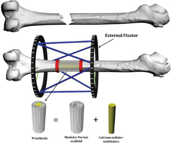
Bone bricks approach for large bone loss treatment.
2. Materials and methods
2.1. Materials
Polycaprolactone (PCL) (CAPA 6500, Mw = 50000Da), a semi-crystalline linear aliphatic biopolymer, was supplied by Perstorp Caprolactones (Cheshire, UK) in the form of pellets. Hydroxyapatite (HA) (Mw = 502.31 r/mol, MP = 1100°C) was supplied by Sigma-Aldrich (St. Louis, USA) in a nanopowder form (<200 mm particles size) and β-tri-calcium phosphate (TCP) (Mw = 310.18 r/mol, MP = 1391°C) was supplied by Sigma-Aldrich (St. Louis, USA) in a nanopowder form (<200 mm particles size). PCL composite blends containing different bioceramics contents (20 wt% HA, 20 wt% TCP, and 10 wt% HA plus 10 wt% TCP) were produced by melt blending. PCL pellets were measured using an electronic weighting high precision balance (precision of 0.0001) and melted at 150°C in a porcelain bowl before adding the ceramic material. Composite materials were mixed around 1 h to ensure a uniform distribution of the ceramics in the polymer matrix and cut down in small pellets after cooling.
2.2. Production
Bone bricks were produced using the material extrusion additive manufacturing 3D Discovery system (RegenHU, Switzerland). A computational geometry-based algorithm, with data collected from anthropometric measurements by surgeons in Turkey, was used to create a continuous path planning algorithm, using zig-zag (25 and 38 double filaments) and spiral-like patterns (6 and 14 filaments) to produce four groups of bone bricks with overall porosity varying between 52% and 74% (Figure 2). The process parameters used for the production of the bone bricks were melting temperature 90°C, deposition velocity of 18 mm/s, and screw rotation velocity of 14 rpm. During the production process, the composite pellets were placed in a heated reservoir, melted, and moved to the screw chamber using compressed air and extruded out with the use of a needle. The composite leaves the extruder in a molten state, cooling down in the working platform. The diameter of the needle was 0.33 mm.
Figure 2.
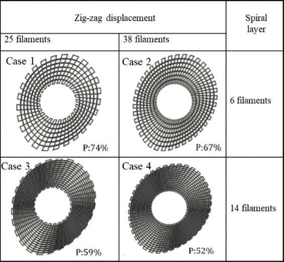
Anthropometric based geometries and different path planning strategies considered to produce bone bricks with different porosities.
2.3. Morphological characterization
The morphology of printed bone bricks was investigated using the scanning electron microscopy (SEM) FEI ESEM Quanta 200 (FEI Company, United States) at an accelerated voltage of 15 kV. EMITECH K550X sputter coater (Quorum Technologies, UK) was used for coating the structures (gold coating) prior imaging. The obtained images were processed by ImageJ (NIH, USA), allowing to determine the PS, the filament width (FW), and the layers gap. For each bone brick, 10 measurements were considered to obtain the average and standard deviation.
2.4. Mechanical characterization
Compression tests were performed on the INSTRON 3344 (Instron, UK) in the dry state with a 2 kN load cell and a displacement rate of 0.5 mm/min, according to the ASTM D695-15. The Bluehill Universal software (Instron, UK) was used to collect the data and to determine the compression modulus (Ec). During the compression tests, the software captured forces, F, and displacement values, automatically converting them into stresses (σ), and strains (ε) as follow:


where h0 is the height of the bone brick, A is the initial cross-section area and Δh is the height variation.
2.5. Biological characterization
Human adipose-derived stem cells (STEMPRO, Invitrogen, USA) were used to investigate bone bricks cytotoxicity and metabolic cell activity on the bone bricks. MesenPRO RSTM basal media, 2% (v/v) growth supplement, 1% (v/v) glutamine, and 1% (v/v) penicillin/streptomycin (Invitrogen, USA) was used for cell culture. Cells (passage 5) were cultured in an incubator (37°C, 5% CO2, and 95% humidity) until an appropriate cell density was achieved (95%) before cell seeding.
Bone bricks were sterilized in 80% ethanol for 4 h, then washed in phosphate-buffered saline (PBS) solution 2 times and left to dry overnight in a sterile laminar flow cabinet. The sterilized bone bricks were transferred into 24 well plates. An 89 ml cell suspension containing 50,000 cells was added into each scaffold at day 0. Then, the well plates were placed in an incubator for 2 h for cell attachment to the bone bricks and 900 ml of media were added into each well plate.
On days 1, 7, and 14, after cell seeding, samples were transferred into new 24 well plates and the media were replaced. Cell metabolic activity was investigated using the Alamar Blue (Sigma-Aldrich, UK) assay which measures the ability of the cells to reduce the resazurin into resorufin by mitochondrial enzyme activity providing indirect information on cell attachment and proliferation[20],[27].
At each time point, 90 ml of 0.001% resazurin solution was added to each bone brick and incubated for 4 h. Two hundred microliters of sample solution were transferred into a 96 well plate for measuring the fluorescence intensity (530 nm excitation/590 nm emission wavelength) using the microplate reader Synergy HTX Multi-Mode Reader (BioTek, United States). Measurements were calculated with the instrument software (Gen5). After measurements, bone bricks were washed 3 times with sterilized PBS to remove the residual Alamar Blue solution and new media were added. Cell media were changed every 2 days.
After 14 days of cell seeding, cell-seeded bone bricks were observed using SEM to assess the cell morphology and attachment. Bone bricks were fixed with 10% neutral buffered formalin (Sigma-Aldrich, Dorset, UK) for 30 min at room temperature. After rinsed 2 times with PBS, samples were dehydrated using a series of graded ethanol (50%, 60%, 70%, 80%, 90%, and 2 times of 100%) for 15 min for each concentration. 50/50 ethanol/hexamethyldisilazane (HDMS) (Sigma-Aldrich, USA) (v/v) solution was then added for 15 min, followed by adding 100% HDMS and drying samples overnight.
2.6. Data analysis
All data are represented as mean ± standard deviation. Mechanical results and biological results are subjected to one-way analysis of variance (one-way ANOVA) and Tukey’s post hoc test with the use of GraphPad Prism software. Significance levels were set at P < 0.05.
3. Results
3.1. Morphological analysis
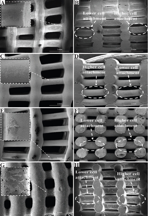
Figure 3 shows the SEM images of the top view of two printed configurations, being possible to observe the PS gradient (the PS decreases from the outside region of the bone bricks to the internal region). Figure 4 shows high magnification SEM images of both top view and cross-section view of printed bone bricks, considering as an example case 2 and all material compositions. FW values are presenting in Table 1, which also indicates the initial designed value (330 mm). Depending on the printed case and material composition differences, up to 24.5% can be observed. These differences can be attributed to the fact that processing conditions were kept constant for all bone bricks topologies and material compositions and can be solved in the future by adjusting the processing conditions aiming to obtain similar values of FW. Results show that PS decreases and FW increases by increasing the bioceramic content. Moreover, for the same configuration and level of reinforcement, FW is higher (lower PS) in HA bone bricks than in TCP bone bricks. The PS also decreases by increasing the number of double filaments (from 25 to 38) and a similar trend was observed for spiral filaments (increasing from 6 to 14). For the same material composition, the PS of bone bricks with the same number of double filaments decreases by increasing the number of spiral filaments. A similar trend was observed for bone bricks with the same number of spiral filaments. In addition, PCL bone bricks showed micropore structures on the surface of the filaments (Figure 4A), while PCL/HA, PCL/TCP, and PCL/HA/TCP bone bricks show less micropores on the filaments surface (Figure 4C, E, G). This can be explained by the effect of the ceramic nanoparticles on the size of the polymer crystals and the recrystallization process inducing a smooth surface of the printed filaments[28].
Figure 3.
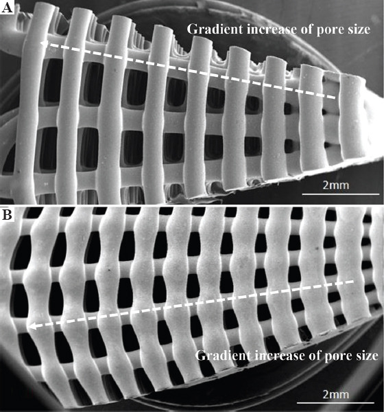
Scanning electron microscopy images of the top view of polycaprolactone bone bricks with different architectures (A) case 1 and (B) case 2.
Figure 4.
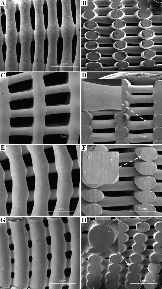
Top and cross-section scanning electron microscopy images of bone bricks (case 2) for different material composition on (A), (B) polycaprolactone bone brick, (C), (D) hydroxyapatite/β-tri-calcium phosphate (HA/TCP) 10 wt%/10 wt% bone brick, (E), (F) HA 20 wt%, and (G), (H) TCP 20 wt% bone brick.
Table 1.
Morphological characteristics of bone bricks structures for different configurations
| Configuration | Case 1 | Case 2 | Case 3 | Case 4 |
|---|---|---|---|---|
| PCL/HA(80/20 wt%) | ||||
| Filament width (μm) | 353±8 | 364±2 | 445±135 | 305±57 |
| Average pore size (μm) | 770±64 | 583±102 | 400±8 | 406±10 |
| PCL/TCP(80/20 wt%) | ||||
| Filament width (μm) | 358±9 | 368±6 | 403±9 | 431±5 |
| Average pore size (μm) | 768±12 | 571±80 | 468±168 | 327±5 |
| PCL/HA/TCP (80/10/10 wt%) | ||||
| Filament width (μm) | 360±16 | 369±6 | 405±3 | 433±5 |
| Average pore size (μm) | 759±85 | 565±124 | 460±191 | 322±61 |
| PCL | ||||
| Filament width (μm) | 374±12 | 374±16 | 401±12 | 411±35 |
| Average pore size (μm) | 741±5 | 532±79 | 435±154 | 303±90 |
3.2. Mechanical analysis
As shown in Figure 5, the mechanical behavior of the bone bricks strongly depends on the architecture and ceramic content. For the same architecture, the compressive modulus increases by increasing the ceramic content, and for the same level of reinforcement, the compressive modulus is higher in bone bricks containing TCP than HA. For bone bricks with the same material composition and the same number of double layers, compressive modulus increases by increasing the number of spiral filaments. Similarly, for bone bricks with the same material composition and the same number of spiral filaments, compressive modulus increases by increasing the number of double filaments. This can be explained by the overall decrease in porosity. Results also show that by controlling the number of double and spiral filaments, it is possible to create bone bricks with compressive modulus in the trabecular region and presenting much higher values than previously reported for standard regular square scaffolds[28]. For rectangular shape scaffolds with PS around 300 mm, results show an increase of compressive modulus from 48 MPa to 75 MP (PCL scaffolds containing 20 wt% of HA) and 88 MPa (PCL scaffolds containing 20 wt% of TCP)[28]. However, produced bone bricks present significantly high compressing modulus (the maximum achieved value was 334.9 MPa), enabling their use for load-bearing applications such as for trabecular bone applications (compressive modulus ranging from 50 to 1500 MPa with the mean value of 194 MPa)[29]-[32].
Figure 5.
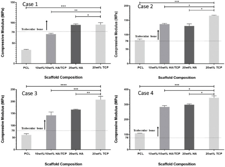
Compressive modulus as a function of bone brick architecture and material composition. *Statistical evidence (P < 0.05) analyzed by one-way analysis of variance and Tukey post-test.
3.3. Biological analysis
Figure 6 shows the fluorescence intensity versus material composition for the four bone bricks architectures at different time points (days 1, 7, and 14) after cell seeding. High fluorescence intensity values correspond to high cell metabolic activity. Results suggest that printed bone bricks do not present any cytotoxicity being able to support cell attachment and proliferation. For all architectures and material composition, cell metabolic activity increases from day 1 to day 7, suggesting cell proliferation. For the same architecture and level of ceramic reinforcement, cell metabolic activity is higher in the HA bone bricks than TCP bone bricks. Statistical high values were obtained for bone bricks containing high levels of HA (20 wt%) and configuration 3. Fluorescence intensity also increases from case 1 (large PS) to case 4 (low PS) as in case 1, cell bridging between filaments is more difficult. Moreover, for the same material composition, case 3 presents high cell metabolic activity than case 4, which can be explained by the high surface area which promotes cell attachment.
Figure 6.
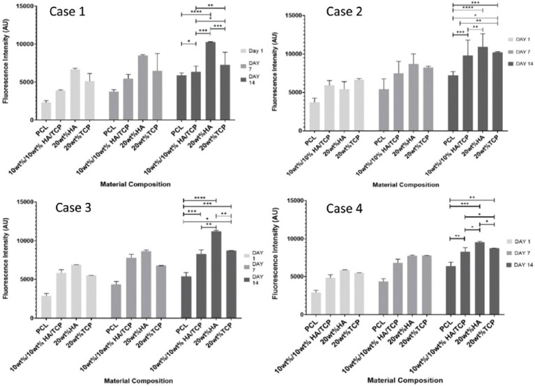
Average fluorescence intensity as a function of bone bricks architecture and material composition for different days after cell seeding. *Statistical evidence (P < 0.05) analyzed by one-way analysis of variance and Tukey post-test.
Figure 7 shows SEM images of bone bricks (case 3) seeded with cells at day 14. Results show that cells are spread over the bone bricks (Figure 7A, C, E, G). It is also possible to observe that cell intensity increases by decreasing the PS, suggesting that the gradient structure is able to induce cell growth in a gradient manner (cross-section images, clearly indicate the effect of cell density as a function of PS) (Figure 7B, D, F, H). Results also show that cell bridging mainly occurs in the crossing sections of adjacent layers and filaments with smaller PS. Cells are also attaching and proliferating but with reduced kinetics on scaffolds presenting different architectures, as shown in Figure 8.
Figure 7.
Top and cross-section scanning electron microscopy images of cells spreading in bone bricks (case 3) with different material compositions (A), (B) polycaprolactone, (C), (D) 10/10 wt% hydroxyapatite/β-tri-calcium phosphate (HA/TCP), (E), (F) 20 wt% HA, and (G), (H) 20 wt% TCP.
Figure 8.
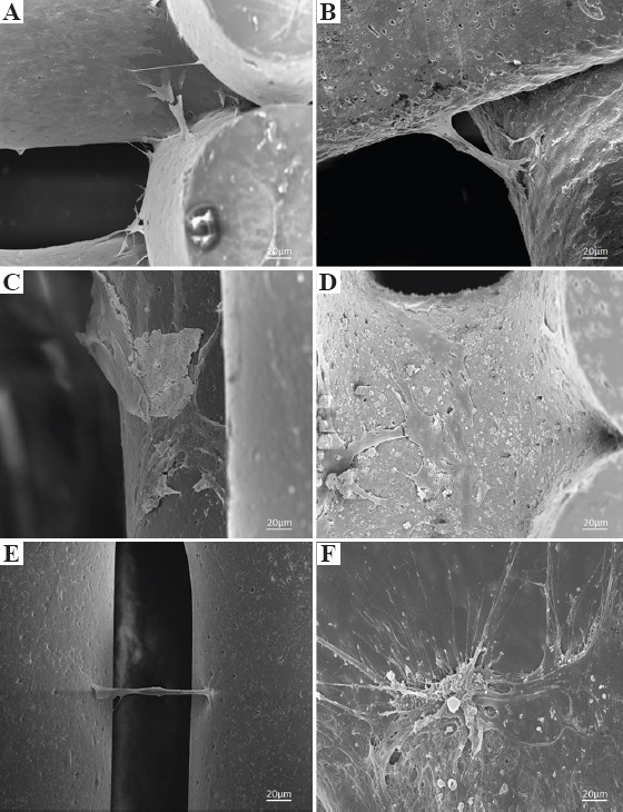
Scanning electron microscopy images of cells attachment and spreading on (A) polycaprolactone bone brick (case 1), (B) 10 wt%/10 wt% hydroxyapatite/β-tri-calcium phosphate (HA/TCP) bone brick (case 2), (C) 20 wt% HA bone brick (case 2), (D) 20 wt% HA bone brick (case 3), (E) 20 wt% TCP bone brick (case 3), and (F) 20 wt% TCP bone brick (case 4).
4. Conclusion
This paper investigates the effects of bone bricks architecture (PS gradient) and material composition (reinforcement and chemical cues) on the morphological, mechanical, and biological properties of printed bone bricks designed according to anthropometric data. Bone bricks with complex architectures mimicking the patient bone structure were successfully produced using a screw-assisted extrusion-based additive manufacturing system. For different architectures were printed, changing the number of double and spiral filaments which also allowed to control the overall porosity. Results show that by controlling both the architecture and material composition, it is possible to control the mechanical and biological performance of the bone bricks. Table 2 summarizes the obtained results, identifying the optimal architecture regarding mechanical and biological behavior. For the same architecture, high mechanical properties were obtained with TCP bone bricks (344.9 MPa), while high cell metabolic activity suggesting high cell attachment and proliferation was obtained with HA bone bricks (11216 AU). Considering both mechanical properties and biological results, case 4 produced with PCL/TCP seems to be the ideal configuration.
Table 2.
Optimal design architectures regarding mechanical and biological performance (darker color corresponds to the optimal case and less dark color to the worst configuration)
| Architecture | Mechanical properties (MPa) | Biological performance (AU) |
|---|---|---|
| Case 1 | 95.4±4.9 | 10262.8±41.6 |
| Case 2 | 165.8±1.7 | 10929±1718.6 |
| Case 3 | 207.8±3.6 | 11216±127 |
| Case 4 | 344.9±2.7 | 9531±139 |
Conflict of interest
All authors declare that they have no conflicts of interest.
Acknowledgments
This project has been supported by the University of Manchester and the EPSRC of the UK, the GCRF, grant number EP/R01513/1.
References
- 1.Dilogo I, Primaputra M, Pawitan J, et al. Modified Masquelet Technique Using Allogeneic Umbilical Cord-derived Mesenchymal Stem Cells for Infected Non-union Femoral Shaft Fracture with a 12 cm Bone Defect:A Case Report. Int J Surg Case Rep. 2017;34:11–6. doi: 10.1016/j.ijscr.2017.03.002. https://doi.org/10.1016/j.ijscr.2017.03.002. [DOI] [PMC free article] [PubMed] [Google Scholar]
- 2.Wiese A, Pape H. Bone Defects Caused by High-energy Injuries, Bone Loss, Infected Nonunions, and Nonunions. Orthop Clin North Am. 2010;41:1–4. doi: 10.1016/j.ocl.2009.07.003. https://doi.org/10.1016/j.ocl.2009.07.003. [DOI] [PubMed] [Google Scholar]
- 3.Giannoudis P, Einhorn T, Marsh D. Fracture Healing:The Diamond Concept. Injury. 2007;38:S3–6. doi: 10.1016/s0020-1383(08)70003-2. https://doi.org/10.1016/s0020-1383(08)70003-2. [DOI] [PubMed] [Google Scholar]
- 4.DeCoster T, Gehlert R, Mikola E, et al. Management of Posttraumatic Segmental Bone Defects. J Am Acad Orthop Surg. 2004;12:28–38. doi: 10.5435/00124635-200401000-00005. [DOI] [PubMed] [Google Scholar]
- 5.Moghaddam A, Thaler B, Bruckner T, et al. Treatment of Atrophic Femoral Non-unions According to the Diamond Concept:Results of One-and Two-step Surgical Procedure. J Orthop. 2017;14:123–33. doi: 10.1016/j.jor.2016.10.003. https://doi.org/10.1016/j.jor.2016.10.003. [DOI] [PMC free article] [PubMed] [Google Scholar]
- 6.Scholz A, Gehrmann S, Glombitza M, et al. Reconstruction of Septic Diaphyseal Bone Defects with the Induced Membrane Technique. Injury. 2015;46:S121–4. doi: 10.1016/S0020-1383(15)30030-9. https://doi.org/10.1016/s0020-1383(15)30030-9. [DOI] [PubMed] [Google Scholar]
- 7.Calori G, Colombo M, Ripamonti C, et al. Megaprosthesis in Large Bone Defects:Opportunity or Chimaera? Injury. 2014;45:388–93. doi: 10.1016/j.injury.2013.09.015. https://doi.org/10.1016/j.injury.2013.09.015. [DOI] [PubMed] [Google Scholar]
- 8.Calori G, Colombo M, Malagoli E, et al. Megaprosthesis in Post-traumatic and Periprosthetic Large Bone Defects:Issues to Consider. Injury. 2014;45:105–10. doi: 10.1016/j.injury.2014.10.032. https://doi.org/10.1016/j.injury.2014.10.032. [DOI] [PubMed] [Google Scholar]
- 9.Parvizi J, Sim F. Proximal Femoral Replacements with Megaprostheses. Clin Orthop Relat Res. 2004;420:169–75. doi: 10.1097/00003086-200403000-00023. https://doi.org/10.1097/00003086-200403000-00023. [DOI] [PubMed] [Google Scholar]
- 10.Vaishya R, Singh A, Hasija R, et al. Treatment of Resistant Nonunion of Supracondylar Fractures Femur by Megaprosthesis. Knee Surg Sports Traumatol Arthrosc. 2011;19:1137–40. doi: 10.1007/s00167-011-1416-1. https://doi.org/10.1007/s00167-011-1416-1. [DOI] [PubMed] [Google Scholar]
- 11.Ashman O, Phillips A. Treatment of Non-unions with Bone Defects:Which Option and Why? Injury. 2013;44:43–5. doi: 10.1016/S0020-1383(13)70010-X. https://doi.org/10.1016/s0020-1383(13)70010-x. [DOI] [PubMed] [Google Scholar]
- 12.Papakostidis C, Bhandari M, Giannoudis P. Distraction Osteogenesis in the Treatment of Long Bone Defects of the Lower Limbs. Bone Joint J. 2013;95-B:1673–80. doi: 10.1302/0301-620X.95B12.32385. https://doi.org/10.1302/0301-620x.95b12.32385. [DOI] [PubMed] [Google Scholar]
- 13.Masquelet A, Begue T. The Concept of Induced Membrane for Reconstruction of Long Bone Defects. Orthop Clin North Am. 2010;41:27–37. doi: 10.1016/j.ocl.2009.07.011. https://doi.org/10.1016/j.ocl.2009.07.011. [DOI] [PubMed] [Google Scholar]
- 14.Taylor B, French B, Fowler T, et al. Induced Membrane Technique for Reconstruction to Manage Bone Loss. J Am Acad Orthop Surg. 2012;20:142–50. doi: 10.5435/JAAOS-20-03-142. [DOI] [PubMed] [Google Scholar]
- 15.Taylor B, Hancock J, Zitzke R, et al. Treatment of Bone Loss with the Induced Membrane Technique. J Orthop Trauma. 2015;29:554–7. doi: 10.1097/BOT.0000000000000338. https://doi.org/10.1097/bot.0000000000000338. [DOI] [PubMed] [Google Scholar]
- 16.Beris A, Lykissas M, Korompilias A, et al. Vascularized Fibula Transfer for Lower Limb Reconstruction. Microsurgery. 2011;31:205–11. doi: 10.1002/micr.20841. https://doi.org/10.1002/micr.20841. [DOI] [PubMed] [Google Scholar]
- 17.Denry I, Kuhn L. Design and Characterization of Calcium Phosphate Ceramic Scaffolds for Bone Tissue Engineering. Dent Mater. 2016;32:43–53. doi: 10.1016/j.dental.2015.09.008. https://doi.org/10.1016/j.dental.2015.09.008. [DOI] [PMC free article] [PubMed] [Google Scholar]
- 18.Oryan A, Alidadi S, Moshiri A, et al. Bone Regenerative Medicine:Classic Options, Novel Strategies, and Future Directions. J Orthop Surg Res. 2014;9:18. doi: 10.1186/1749-799X-9-18. https://doi.org/10.1186/1749-799x-9-18. [DOI] [PMC free article] [PubMed] [Google Scholar]
- 19.Tang D, Tare R, Yang L, et al. Biofabrication of Bone Tissue:Approaches, Challenges and Translation for Bone Regeneration. Biomaterials. 2016;83:363–82. doi: 10.1016/j.biomaterials.2016.01.024. https://doi.org/10.1016/j.biomaterials.2016.01.024. [DOI] [PubMed] [Google Scholar]
- 20.Borra R, Lotufo M, Gagioti S, et al. A Simple Method to Measure Cell Viability in Proliferation and Cytotoxicity Assays. Braz Oral Res. 2009;23:255–62. doi: 10.1590/s1806-83242009000300006. DOI:10.1590/s1806-83242009000300006. [DOI] [PubMed] [Google Scholar]
- 21.Lichte P, Pape H, Pufe T, et al. Scaffolds for Bone Healing:Concepts, Materials and Evidence. Injury. 2011;42:569–73. doi: 10.1016/j.injury.2011.03.033. https://doi.org/10.1016/j.injury.2011.03.033. [DOI] [PubMed] [Google Scholar]
- 22.Liu F, Huang B, Hinduja S, et al. Biofabrication Techniques for Ceramics and Composite Bone Scaffolds. In: Antoniac I, editor. Bioceramics and Biocomposites:From Research to Clinical Practice. John Wiley and Sons; Hoboken, New Jersey: 2019. pp. 17–37. https://doi.org/10.1002/9781119372097.ch2. [Google Scholar]
- 23.Bartolo P, Kruth J, Silva J, et al. Biomedical Production of Implants by Additive Electro-chemical and Physical Processes. CIRP Ann. 2012;61:635–55. [Google Scholar]
- 24.Bártolo P, Chua C, Almeida H, et al. Biomanufacturing for Tissue Engineering:Present and Future Trends. Virtual Phys Prototyp. 2009;4:203–16. [Google Scholar]
- 25.Lee J, Ng W, Yeong W. Resolution and Shape in Bioprinting:Strategizing towards Complex Tissue and Organ Printing. Appl Phys Rev. 2019;6:011307. https://doi.org/10.1063/1.5053909. [Google Scholar]
- 26.Ng W, Chua C, Shen Y. Print Me An Organ!Why We Are Not There Yet. Prog Polym Sci. 2019;97:101145. DOI:10.1016/j.progpolymsci.2019.101145. [Google Scholar]
- 27.Vega-Avila E, Pugsley MK. An Overview of Colorimetric Assay Methods Used to Assess Survival or Proliferation of Mammalian Cells. Proc West Pharmacol Soc. 2011;54:10–4. [PubMed] [Google Scholar]
- 28.Huang B, Caetano G, Vyas C, et al. Polymer-Ceramic Composite Scaffolds:The Effect of Hydroxyapatite and β-tri-calcium Phosphate. Materials. 2018;11:129. doi: 10.3390/ma11010129. https://doi.org/10.3390/ma11010129. [DOI] [PMC free article] [PubMed] [Google Scholar]
- 29.Lotz J, Gerhart T, Hayes W. Mechanical Properties of Trabecular Bone from the Proximal Femur. J Comput Assist Tomogr. 1990;14:107–14. doi: 10.1097/00004728-199001000-00020. https://doi.org/10.1097/00004728-199001000-00020. [DOI] [PubMed] [Google Scholar]
- 30.Thomson R, Yaszemski M, Powers J, et al. Fabrication of Biodegradable Polymer Scaffolds to Engineer Trabecular Bone. J Biomater Sci Polym Ed. 1996;7:23–38. doi: 10.1163/156856295x00805. [DOI] [PubMed] [Google Scholar]
- 31.Porter B, Oldham J, He SL, et al. Mechanical Properties of a Biodegradable Bone Regeneration Scaffold. J Biomech Eng. 2000;122:286–8. doi: 10.1115/1.429659. [DOI] [PubMed] [Google Scholar]
- 32.Williams J, Adewunmi A, Schek R, et al. Bone Tissue Engineering Using Polycaprolactone Scaffolds Fabricated via Selective Laser Sintering. Biomaterials. 2005;26:4817–27. doi: 10.1016/j.biomaterials.2004.11.057. https://doi.org/10.1016/j.biomaterials.2004.11.057. [DOI] [PubMed] [Google Scholar]