

Abstract
NiTi alloy has a wide range of applications as a biomaterial due to its high ductility, low corrosion rate, and favorable biocompatibility. Although Young’s modulus of NiTi is relatively low, it still needs to be reduced; one of the promising ways is by introducing porous structure. Traditional manufacturing processes, such as casting, can hardly produce complex porous structures. Additive manufacturing (AM) is one of the most advanced manufacturing technologies that can solve impurity issues, and selective laser melting (SLM) is one of the well-known methods. This paper reviews the developments of AM-NiTi with a particular focus on SLM-NiTi utilization in biomedical applications. Correspondingly, this paper aims to describe the three key factors, including powder preparation, processing parameters, and gas atmosphere during the overall process of porous NiTi. The porous structure design is of vital importance, so the unit cell and pore parameters are discussed. The mechanical properties of SLM-NiTi, such as hardness, compressive strength, tensile strength, fatigue behavior, and damping properties and their relationship with design parameters are summarized. In the end, it points out the current challenges. Considering the increasing application of NiTi implants, this review paper may open new frontiers for advanced and modern designs.
Keywords: NiTi, Additive manufacturing, Orthopedic implants, Porous structure, Mechanical properties
1. Introduction
In recent years, shape memory alloys (SMAs) have been widely used in aerospace and biomedical fields due to their excellent shape memory effect (SME) and superelasticity[1-4]. SMA is a smart material that can convert thermal energy into mechanical work to achieve certain mechanical properties[5,6]. Among many SMAs, NiTi has the best shape memory properties, including high shape recovery, recovery stress, and superelastic strain[5]. Therefore, NiTi can be found in various applications, such as actuators[6], aerospace[5], orthopedic implants and fixtures[5], couplings and fasteners[6], electrical safety devices[7], microelectromechanical systems[7], navy[8], sports equipment[8], surgical instruments[8], and so on.
There are two different phases in SMAs, called austenite phase (high-temperature phase) and martensite phase (low-temperature phase)[9]. The transformation between the two phases is not through atomic diffusion but due to the sheer lattice distortion, called martensitic transformation[8]. There are two forms of martensite variant assembly: Twinned martensite (Mt) composed of self-accommodated martensite variants, and detwinned martensite (Md) consisting of detwinned or reoriented martensite variants[8]. When the Mt at low temperature is loaded, the martensite can be detwinned by reorienting a part of the deformation. When the load on the Md is released, the deformed shape retains, and then the SMA is heated to a temperature higher than Af (from Md to austenite), resulting in complete shape recovery, as Figure 1 shows. This specific phenomenon is called the SME. When SMAs is above the austenite transformation temperature, the enormous strain generated during the loading process will gradually recover with unloading, called superelasticity or pseudoelasticity[10].
Figure 1.

(A) Schematic of shape memory effect in NiTi. (B) A typical Shape Memory Alloys pseudoelastic loading cycle[8] (Shape Memory Alloys, Introduction to Shape Memory Alloys, 2008, 1–51, P.K. Kumar, D.C. Lagoudas. with permission from Springer).
Due to its high ductility, low corrosion rate, and good biocompatibility[11], Wang et al.[12-16] have carried out a series of researches on the application of NiTi-based SMAs in biomedical fields. Moreover, the mechanical hysteresis of NiTi is very similar to natural bone, making it an ideal choice for orthopedic implants[17]. Commonly used biomedical alloys, such as titanium alloy, cobalt-based alloy, and stainless steel have Young’s modulus of 110 GPa, 190 Gpa, and 210 GPa, respectively[16], which is much higher than human cancellous bone (<3 GPa) or cortical bone (12–20 GPa)[18]. When loading, the implant with much higher Young’s modulus withstands most of the stress, and the stress level of the bone is considerably low, which is called the stress shielding effect[19]. If the loading force on the bone is too small for a long time, it will cause bone resorption and loosening of the implant and ultimately cause implantation failure[20]. The Young’s modulus of NiTi is much lower (40–60 GPa), but it is still necessary to further reduce it. Table 1 shows the mechanical properties of natural human bone and biomedical metallic materials.
Table 1.
Mechanical properties of biomedical metallic materials and natural human bone
Producing a porous structure is the most common method to reduce Young’s modulus[24]. Traditional alloy manufacturing processes such as casting cannot produce complex porous structures economically and efficiently. NiTi is sensitive to composition and difficult to machine due to its poor machinability[25]. Therefore, most conventionally produced NiTi parts have simple geometric shapes, such as wire, plate, strip, and tube, which severely limits the full potential applicability of NiTi[25]. For overcoming the manufacturing problems of complex structures, the current better solutions are powder metallurgy (PM) and additive manufacturing (AM). Most of the PM-NiTi components have high impurities like intermetallic phases[26], which may significantly reduce the mechanical properties of NiTi. In most cases, the formation of these second phases is inevitable because their formation is more thermodynamically stable than NiTi[27]. Usually, these inclusions are carbides TiC, intermetallic oxide Ti4Ni2Ox, or intermetallic phases, such as NiTi2, Ni3Ti, and Ni4Ti3[28]. Although Ni4Ti3 precipitates are highly needed, carbides and oxides are not favorable because they are not beneficial to corrosion resistance, biocompatibility, and transformation temperature, so PM technology unfortunately will bring many disadvantages and limitations during the fabrication of porous NiTi[29].
AM is a novel manufacturing technology applied to various materials and is considered one of the most advanced manufacturing technologies[30]. AM can overcome PM-related impurity issues such as O2 and N2 inclusion. For example, the SLM chamber has an inert argon atmosphere, which can significantly avoid any possible contamination such as impurity gas and Ni evaporation[29]. For electron beam melting (EBM), its vacuum environment is also conducive to reducing impurity gas[31]. AM technology can be divided into powder bed-based technology, such as selective laser melting (SLM) and electron beam melting (EBM), or fluidization-based technology, such as directed energy deposition (DED)[32]. Powder bed-based technology processes powder deposition through rollers, blades, or knives, while fluidization-based technology deposits powder through one or more nozzles that feed the powder directly into the laser focus. Figures 2 and 3 show the SLM and DED processes, respectively.
Figure 2.

Powder bed fusion laser process[40] (Reprinted from Additive Manufacturing, 8, S. M. Thompson, L. Bian, N. Shamsaei, et al., An overview of Direct Laser Deposition for additive manufacturing; Part I: Transport phenomena, modeling, and diagnostics, 36–62, Copyright (2015), with permission from Elsevier).
Figure 3.

DED/LENS process. (A) Laser head set up. (B) Powder feeding setup[41] (Lasers in Manufacturing and Materials Processing, Effects of Composition and Post Heat Treatment on Shape Memory Characteristics and Mechanical Properties for Laser Direct Deposited Nitinol, 6, 2019, 41–58, J. Lee, Y. C. Shin. With permission from Springer).
Considering the relatively low accuracy of DED technology, powder bed fusion technology is more prevalent when manufacturing complex microstructures. EBM can be used as an essential technology for the production of metallic biomedical materials. Wang et al.[22,33] conducted a series of studies on the production of Ti-6Al-4V by EBM. Few reports are available regarding EBM-NiTi[34-36]. The high vacuum conditions of EBM are suitable for reactive materials such as NiTi[37]. However, due to poor surface roughness, the fatigue performance of EBM parts is terrible[38]. Furthermore, the preheating stage of EBM is not suitable for preparing NiTi[39]. Therefore, this paper reviews the recent developments of AM-NiTi, especially SLM-NiTi, as orthopedic implants, the porous structure design, and mechanical properties. Furthermore, the relationship between SLM-NiTi properties and various influencing factors and the characterization methods for AM-NiTi implants are also summarized and finally, current challenges were discussed.
2. Influencing factors in SLM-NiTi production
For metallic AM in biomedical applications, powder bed-based technology is much more prevalent in creating complex geometry[25]. Due to its high resolution, the most common manufacturing method to produce NiTi is SLM. The production process for SLM utilization in NiTi includes three main factors: powder preparation, processing parameters, and gas atmosphere[42]. In terms of powder preparation, the Ni/Ti ratio is an essential factor in ensuring the required functional properties (SME or superelasticity) of the final part. At room temperature, parts made of Ti-rich NiTi have a SME[43], while parts made of Ni-rich NiTi exhibits superelasticity after annealing or aging treatment[44]. In SMAs, the SME and superelasticity are mutual processes. When the transformation temperature is higher than the environment, SMA exhibits the SME, and when environment temperatures lower than the transformation temperature, the material exhibits superelasticity[45]. Therefore, the Ni/Ti ratio must be selected according to the target characteristics to ensure the particular mechanical behavior of the part after fabrication. In terms of processing parameters, the SLM parameters significantly influence the quality of the final NiTi parts.
On the one hand, the NiTi parts produced must be dense. Otherwise, it will seriously deteriorate the mechanical properties, mainly related to the processing parameters[46]. On the other hand, the processing parameters will affect the transformation temperature of NiTi parts. To ensure the satisfactory behavior of the parts in practical applications, the transformation temperature must be controlled by controlling the processing parameters[47]. In terms of gas atmosphere, an inert atmosphere such as argon and nitrogen or even vacuum needs to be provided throughout the SLM process to minimize the oxidation and impurity absorption (such as O2 and C) to improve the surface quality, density, and similarity with conventionally processed NiTi samples[48]. For example, according to ASTM F2063-05, the impurity content of produced parts should be <500 ppm[49].
Farber et al.[48] analyzed the influence of SLM process parameters on the martensite transformation temperature range. The authors believed that two main issues are influencing the NiTi martensite transformation temperature during SLM. On the one hand, Ni evaporates during laser processing, and the matrix components move in the direction of high Ti content, which increases the martensite transformation temperature. On the other hand, in Ni-rich NiTi, high temperature may cause the formation of the Ni-rich phases. For example, at 200–700°C, the order of precipitation in NiTi is Ni4Ti3→Ni3Ti2→Ni3Ti+Ni4Ti3+Ni3Ti2. Due to the precipitation phase generation, the Ni content in the matrix decreases. As a consequence, the martensite transformation temperature increases[11]. The lower the martensite transformation temperature, the worse the shape memory performance. The heat treatment after SLM can partially solve the problem of phase transformation temperature drift. Lee et al.[41] summarized the NiTi transformation temperature range in different Ni content. Figure 4 shows that when the Ni content is between 51 and 52 (% .at) the NiTi transformation temperature will change drastically. Therefore, the content of Ni must be strictly controlled to obtain an ideal transformation temperature.
Figure 4.

Transformation temperatures according to Ni contents[41] (Lasers in Manufacturing and Materials Processing, Effects of Composition and Post Heat Treatment on Shape Memory Characteristics and Mechanical Properties for Laser Direct Deposited Nitinol, 6, 2019, 41–58, J. Lee, Y. C. Shin. With permission from Springer).
Biffi et al.[50] investigated the SLM processability in the production of fully dense NiTi parts, microstructure, and the superelastic response of samples under different parameters. The results show that the laser fluence in the range of 63–160 J/mm3 can cause the highest relative density. Depending on the cooling rate and the size of the molten pool, the microstructure of the sample can have different degrees of orientation. By heat treatment at 500°C, it can attain a fully recoverable strain up to 6%, which shows that the annealing treatment can promote the superelasticity of the sample. Yang et al.[51] explained that different scanning speeds affect the phase composition, leading to critical stress and mechanical recovery strain changes. Khoo et al.[52] proposed a new method – repetitive laser scanning. Figure 5 shows the schematic of differences in laser absorptivity and heat conductivity. The results show that the phase transformation characteristics of the sample are similar to NiTi powder, and it can withstand the tensile load up to 5.11%, which is equivalent to that of traditional NiTi parts. It provides a new idea for manufacturing high-performance SLM-NiTi parts.
Figure 5.

Laser absorptivity and heat conductivity. (A) P25. (B) P40. (C) P60[52] (Shape Memory and Superelasticity, Fabrication of SLM NiTi Shape Memory Alloy through Repetitive Laser Scanning, 4, 2018, 112–120, Z. X. Khoo, Y. Liu, Z. H. Low, et al. with permission from Springer).
Saedi et al.[53] used SLM to manufacture dense and porous (32–58%) NiTi parts and the parts are then heat-treated (solution annealing and aging). The results show that SLM-NiTi with a porosity of up to 58% can show the SME, and it can fully recover under 100 MPa nominal stress. The dense SLM-NiTi shows outstanding superelasticity after 6% deformation at body temperature, with a recovery rate of 5.65%. The strain recovery of samples with porosities of 32%, 45%, and 58% was about 3.5%, 3.6%, and 2.7%, respectively. The same researchers have studied the influence of SLM process parameters on NiTi transformation temperature[48] and the compactness of parts[50]. Through improved processes, such as repetitive laser scanning, they obtained performance comparable to conventional NiTi parts[52]. Yang et al.[54] found that when preparing thinner struts (thickness <0.6 mm), a lower scanning speed performs better. Besides, these researchers investigated porous SLM-NiTi performance and found that as the porosity increases, the strain recovery rate decreases slightly, putting forward a requirement for the upper limit of the porosity[53]. Fu et al.[55] used micro-SLM technology (with a laser beam of 25 μm) to explore the defects, microstructure, and thermomechanical behavior of micro-SLM-NiTi parts. The authors comprehensively analyzed the formation mechanism of defects, including pores, unmelted areas, and cracks. At the same time, they creatively proposed the process window for scanning speed and hatch distance to produce micro-SLM-NiTi with few gas pores and no cracks, as shown in Figure 6. All the above studies have provided technical guidance for the production of dense and defect-free SLMed NiTi.
Figure 6.

Scanning speed-Hatch distance window[55] (Reprinted from Optics & Laser Technology, 131, J. Fu, Z. Hu, X. Song, et al., Micro selective laser melting of NiTi shape memory alloy: Defects, microstructures, and thermal/mechanical properties, 106374, Copyright [2020], with permission from Elsevier).
3. Design of porous structures
In orthopedic surgery, NiTi applications include compression bone stabilizers for osteotomy and fracture fixation[56], rods for correcting scoliosis[57], and shape memory for cervical surgery expansion clip[58], small bone clip surgery[59], and tissue suture fixation system for minimally invasive surgery[60].
Utilization of a porous structure in NiTi as an orthopedic implant is very beneficial. Although NiTi has a low Young’s modulus (40–60 GPa), it is still high compared to natural human bone[18]. It is necessary to further reduce Young’s modulus by increasing porosity. On the other hand, pores are essential for forming osteoblasts and the proliferation of mesenchymal cells[61]. The porous surface also improves the mechanical interlocking between the implant and the surrounding natural bone, providing higher mechanical stability at the interface[62]. Kuboki et al.[61] demonstrated the necessity of pores in bone regeneration, they found no new bone formed on the solid particles, but direct osteogenesis occurred in the porous scaffold.
Traditional production technologies used to form pores in biomedical materials include salt immersion method, gas foaming method[63], phase separation method, freeze casting method[64], and sintering method[65]. The most significant disadvantage of these technologies is that they cannot accurately control parameters such as pore shape, pore size, and porosity. Now that AM technology has matured, it is a general trend to directly design and manufacture porous parts. The biggest advantage of AM technology in porous structure design is that it can accurately manufacture complex structures without further process and retain the original mechanical and biological properties.
Figure 7 shows the overall process of porous AM-NiTi implants. The critical step in producing the porous AM-NiTi biomaterials is designing the unit cell and the pore parameters, including pore size, porosity, pore shape, and interconnectivity. After that, the AM parameters, heat treatment[15], surface modification[66-68], and drug-loading[69,70] are also needed.
Figure 7.
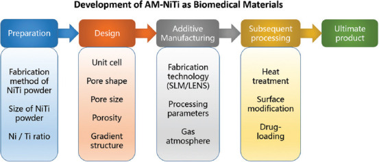
Overall process of manufacturing porous additive manufacturing-NiTi implants.
3.1. Unit cell design
In AM-produced porous NiTi implants, the first step is to design the 3D model of scaffold structure and the computer-aided design (CAD) model focusing on unit cell design. According to Bael et al.[71], SLM cannot create geometrically accurate and high-quality overhanging parts. The six different unit cells designed by Bael et al.[72] are shown in Figure 8, in which the pore shapes are based on the research of Rumpler[73], which consists of triangle hexagon and rectangle. Subsequently, the printed porous scaffold was analyzed to explore the influence of pore size, pore shape, and permeability on osteogenesis. Li et al.[74] used SLM to produce metallic microlattice and epoxy interpenetrating phase composites and the unit cell design is shown in Figure 9. The results showed that the composites obtained have much higher strength and an excellent specific energy absorption capacity of up to 46 J/g. Furthermore, Wang et al.[22,75] conducted a series of studies on the unit cell design of porous Ti-6Al-4V, such as introducing two different sizes of pores to achieve coupling functions (Figure 10) and millimeter-level pores in novel gyroid lattices (Figure 11). The above works have significant guiding value for the unit cell design of porous NiTi in biomedical applications.
Figure 8.

(A) Unit cells. (B) Optical microscopy images. (C) SEM images. (D) Models based on micro-computed tomography[72] (Reprinted from Acta Biomaterialia, 8(7), B. S. Van, Y. C. Chai, S. Truscello, et al., the effect of pore geometry on the in vitro biological behavior of human periosteum-derived cells seeded on selective laser-melted Ti6Al4V bone scaffolds, 2824–2834, Copyright (2012), with permission from Elsevier).
Figure 9.

Schematic diagram of composites unit cell design and SLMed parts[74] Reprinted from Composites Part A: Applied Science and Manufacturing, 135, X. Li, Y. H. Tan, P. Wang, et al., metallic microlattice and epoxy interpenetrating phase composites: Experimental and simulation studies on superior mechanical properties and their mechanisms, 105934, Copyright (2020), with permission from Elsevier.
Figure 10.

Schematic diagram of the unit cell with two different pore sizes[22] (Reprinted from Additive Manufacturing, 36, P. Wang, X. Li, Y. Jiang, et al., electron beam melted heterogeneously porous microlattices for metallic bone applications: Design and investigations of boundary and edge effects, 101566, Copyright (2020), with permission from Elsevier).
Figure 11.

Millimeter-level pores in novel gyroid lattices[75]. (Reprinted from Journal of Material Science & Technology, 62, P. Wang, X. Li, S. Luo, et al., additively manufactured heterogeneously porous metallic bone with biostructural functions and bone-like mechanical properties, 173–179, Copyright (2021), with permission from Elsevier).
3.2. Pore size
Micro-computed tomography (CT) is a procedure including the isotropic slice data collection and reconstruction into a 2D image, and then the data must be compiled and analyzed to generate a 3D image with quantitative morphological details[76]. This technique is attractive because it is non-invasive and can be used to image and quantify bone repair. The optimal pore size of hydroxyapatite has been measured before, and the estimated value of the optimal pore size is between 150 and 500 μm[77]. It was believed that under the non-weight-bearing conditions, even if the pore size is in the range of 50–125 μm, using porous titanium implants is capable of ensuring good bone ingrowth[78].
The pore size has an important influence on the progress of osteogenesis. Hydroxyapatite scaffolds with small (90–120 μm) and large (350 μm) pores were used for BMP-2 delivery and implanted subcutaneously in rats[50]. Cartilage formation occurs in the small pores before bone formation. Enhanced blood vessel formation was observed in large diameter pores, leading to higher oxygen tension and nutrient supply, and facilitating direct osteogenesis[50]. Gotz et al.[79] found that 200 μm pore size is more suitable for early osseointegration, and 300 μm pore size is conducive to forming lamellar bone. Although the low permeability of small pores may hinder cell ingrowth and blood diffusion, large pores (>300 μm) facilitate the absorptions of nutrients and oxygen into the inner pores and promote the process of blood vessel formation[65]. By constructing a functional graded porous structure, different pore sizes can be combined and used to promote the osteogenesis process. Taniguchi et al.[80] evaluated the effect of pore size on osteogenesis of SLM porous titanium implants in rabbits. They produced three types of porous titanium implants named P300, P600, and P900, with a porosity of 65% and respective average pore size of 309, 632, and 956 μm, as shown in Figure 12. The pore structure of the P600 implant showed the most suitable porous structure for orthopedic implants manufactured by SLM due to its proper mechanical strength, high fixation ability, and rapid bone ingrowth. The bone ingrowth of the P300 implant is lower than the P600 and P900 implants, which can be explained by the formation level of blood vessels.
Figure 12.

Basic single unit and computer-aided design of porous-surfaced titanium plates. (A) A single unit of diamond crystal lattice. (B) P300. (C) P600. (D) P900[80] (Reprinted from Materials Science and Engineering: C, 59, N. Taniguchi, S. Fujibayashi, M. Takemoto, et al., effect of pore size on bone ingrowth into porous titanium implants fabricated by additive manufacturing: An in vivo experiment, 690–701, Copyright (2016), with permission from Elsevier).
Wang et al.[81] reported that the increment of the pore size could lead to an increase in the size of the generated blood vessels. However, the degree of vascularization with pore sizes larger than 400 μm did not increase significantly. Based on these findings, in terms of angiogenesis, implants with larger pore sizes (>400 μm) are more advantageous. On the other hand, a higher average curvature can induce higher tissue expansion in vitro[82]; since the curvature is inversely proportional to the pore size, smaller pores have advantages in curvature effect on osteogenesis[83]. Considering these factors, in terms of bone ingrowth, the shortcomings of P300 implants compared to P600 and P900 implants are the poor blood vessel formation. While for P900 implants, their osteogenesis effect are worse than P600 implants due to the lower curvature.
According to the incubation time and the pore size, Joly et al.[84] analyzed the general behavior of human fibroblasts in the pore filling process and the pore size, as shown in Figure 13. After 24 hours, human fibroblasts were spread entirely on the wall of the scaffold. They observed fibroblast formation throughout the pores with no complete pore filling in the medium and large pore size categories after 3 days. After 7 days, all wells were closed and filled with cells. However, there is still no consensus in terms of the pore size. The currently reported optimal pore size range is 300–900 μm, and the primary selection basis is the osteogenic effect after implantation. The final determination of the pore size also needs to consider the mechanical properties of the material itself while meeting the requirement of pore size for osteogenesis. Furthermore, the mechanical properties of the implant must fulfill requirements for clinical use. The optimal pore size of porous NiTi implants still needs further exploration.
Figure 13.

Confocal microscopy for visualization of the actin cytoskeleton (green) and cell nuclei (blue) to illustrate the filling of scaffold pores by human fibroblasts at day 1, 3, and 7 for the three pore size categories (scale bar equals 100 mm) (from ref.[84] licensed under Creative Commons Attribution 3.0 license).
3.3. Porosity
Porosity defines as the percentage of void space in a solid, which is an inherent morphological characteristic of the material. There are different methods to measure the porosity and pore size of the scaffold. The total porosity (п) is measured and calculated by the gravimetric method[85], as the following equation

In which ρmaterial is the density of material itself, and ρscaffold is the apparent density of the scaffold measured by dividing the mass of the scaffold by the volume of the scaffold[65].
The type of bone in-growth depends on the pore size and porosity. Larger pores are conducive to direct bone formation because they allow blood vessel formation and hyperoxygenation, while smaller pores lead to osteochondrosis[86]. However, the mechanical properties and degradation rate determine the upper limits of pore size and porosity.
The intrinsic properties of a material, porosity, and processing methods can determine the mechanical properties of porous implants. As the material and processing method fixed, the porosity cannot be so high that it cannot meet the mechanical performance requirements. Scaffolds made of biomaterials with high degradation rates should not have high porosity (>90%) because the rapid consumption of biomaterials will damage their mechanical and structural integrity[87]. In contrast, scaffolds made of biomaterials with low degradation rates and robust mechanical properties can be highly porous.
Zheng et al.[88] manufactured three porous titanium implants (with 30%, 40%, and 50% volume fraction of NaCl occupying space, named A30, A40, and A50, respectively) through metal injection molding (MIM). As the volume fraction of NaCl increases from 30% to 50%, the mechanical properties of porous titanium samples decrease. The compressive strength reduces from 316.6 ± 11.4 MPa to 63.2 ± 12.8 MPa, the yield strength reduces from 284.9 ± 9.8 MPa to 59.8 ± 10.2 MPa, and the elastic modulus reduces from 3.0 ± 1.0 GPa to 1.1 ± 0.6 GPa. The result shows that the A30 sample has the best mechanical properties. The yield strength of the A50 sample is about 59.8 MPa, which is less than the yield strength of cortical bone (80–120 MPa) and close to that of human trabecular bone (0.2–80 MPa)[89]. The modulus of elasticity (1.1 GPa) of the A50 sample is much lower than cortical bone (17 GPa)[90] and is close to the human trabecular bone (0.5–4.0 GPa)[89]. Figure 14 shows the optical microscope photographs of Goldner’s staining and non-decalcified sections after being implanted for 28, 56, and 84 day. At 28 day, there was no osseointegration between the three kinds of porous implants. At 56 day, the majority of new bone tissue stuck to the implant surface. At 84 day, the porous implant and the host bone tissue were tightly bonded. The deep and surface pores of the porous implant are overgrown with vascular-like tissue and mineralized bone matrix. The bone tissues of the A40 and A50 groups were deeper than those of the A30 group[88].
Figure 14.

Optical microscope images of Goldner’s staining and non-decalcified sections after being porous-titanium-implanted for 28, 56, and 84 day[88] (Reprinted from Transactions of Nonferrous Metals Society of China, 29(12), J. Zheng, L. Chen, D. Chen, et al., effects of pore size and porosity of surface-modified porous titanium implants on bone tissue ingrowth, 2534–2545, Copyright (2019), with permission from Elsevier).
3.4. Pore shape
Irfan et al.[91] used NaCl powder (N400-60% rectangular and N400-60% spherical) as a gasket during the sintering process to prepare porous NiTi with the same porosity but different pore shapes. The mechanical properties and microstructure of the porous NiTi samples were analyzed, as shown in Figure 15. Two pore shapes of NiTi have similar Young’s modulus (rectangular pores 1.38 GPa spherical pores 1.98 GPa), but the spherical pore NiTi has higher compressive strength (rectangular pores 68 MPa and spherical pores 107 MPa). The increase in compressive strength attributes to the spherical shape, which significantly avoids the stress concentration. The sharp edge provides a location for crack initiation during the deformation process, and the elimination of stress concentration can generate more energy absorption before fracture[91].
Figure 15.

(A) The mechanical properties of NiTi with cubic and spherical pores. (B and C) The SEM images of fractured samples[91] (Reprinted from Materials Letters, 154, I. H. Abidi, F. A. Khalid, M. U. Farooq, et al., tailoring the pore morphology of porous nitinol with suitable mechanical properties for biomedical applications, 17–20, Copyright (2015), with permission from Elsevier).
According to Bael et al.[72], when the scaffold was cultured in growth medium without osteogenic differentiation inducer, only the triangular unit cell scaffold with a pore size of 500 μm had significantly increased ALP activity. According to Reilly and Engler[92], in addition to growth factors, mechanobiological stimulation in the scaffold structure can also promote cell differentiation. The authors speculated that the pore size would affect the perception of the environment, and the cells will feel various stimuli from different pore sizes on the surface[93]. For triangular pores with smaller pore sizes, sharp angles with restricted pore sizes, in which cells can attach to different structs, leading to cell differentiation. Bael et al.[72] also believed that triangular pores might benefit cell proliferation and differentiation, while circular pores can delay pore blockage. Combining pores of different shapes and taking advantage of their respective advantages may be a potential design direction in the future.
3.5. Interconnectivity
Earlier researches have shown that porous implants must have interconnected pores to provide space for the vascular tissue required for continuous mineralized bone ingrowth[94]. Otsuki et al.[95] considered that the interconnection of pores is a critical factor in bone ingrowth, and properly interconnected pores can promote bone ingrowth and differentiation.
Zheng et al.[88] reported that the degree of bone ingrowth of implants with a porosity of 30% (A30) was lower than that of A40 and A50 implants. It is mainly due to the different blood vessel formation degrees, which is essential for bone formation[53]. The degree of formation of blood vessels with a pore size >400 μm increased significantly. In terms of angiogenesis, A40 and A50 implants have more advantages than A30 implants, indicating that suitable pore size and good interconnectivity are essential for bone and vascular tissue ingrowth. An adequate blood supply is necessary for a good combination of bone and porous implants[96]. In addition to providing nutrition, the capillaries in the bone tissue can also coordinate the migration and differentiation of bone cells by delivering functional factors[97].
According to Oers et al.[98], the contact energy with the bone (hb) is a function of the osteocyte signal (S) of bone cells in adjacent bone elements, as shown in Figure 16. Two signal thresholds S0 and S1 are used. If the osteoclast signal is lower than S0, the osteoclast bone adhesion is strong. Between S0 and S1, the adhesion weakens, and above S1, there is no adhesion. The Haversian system is a necessary structural unit to support long bones, and its pore size is 50–250 μm. For bone formation in the pores, the pore size must be larger than the Haversian system. The length of osteoblasts is 20 μm and the capillary diameter is 10–15 μm[98].
Figure 16.

(A) hb is a function of S. (B) Configurations of minimal surface energy for different hb[98] (Reprinted from Bone, 43(3), R. F. M. V. Oers, R. Ruimerman, B. V. Rietbergen, et al., relating osteon diameter to strain, 476–482, Copyright (2008), with permission from Elsevier).
Simultaneously, the size of the interconnected pores is crucial for the migration of cells and blood vessels[99]. In theory, for cells and blood vessels to pass through the pore smoothly, the pore size must be larger than 35 μm. It is impossible to have capillaries and osteoblasts in the connected pores due to the need for space in the process of cell migration and vascular growth[65]. Furthermore, it confirms that the porous structure with 50–300 μm pore size and good connectivity is conducive to bone tissue formation[88].
In summary, good interconnectivity is an essential condition for bone ingrowth after implantation. In summary, good interconnectivity and proper pore parameters jointly lead to the optimization of osteogenesis effects.
3.6. Relationship between mechanical properties and pore parameters
As mentioned above, porous biomaterials must provide mechanical performance requirements in the design step. Figure 17 shows a summary of the relationship between mechanical properties and pore parameters of porous samples. In Figure 17A, the pore size of NiTi is 400 μm, and the porosity is 63.5%. The pore size of Ti-6Al-4V is 500 μm and the porosity is 68.37% (triangular), 42.34% (hexagonal), and 66.65% (rectangular), respectively. In Figure 17B, the porosity of CP-Ti is 70%, the porosity of NiTi is 63.8%, and the porosity of Ti-6Al-4V is 42.34%. In Figure 17C, the pore size of Ti-6Al-4V is 282 μm (29%) and 596 μm (51%), respectively. The pore size of CP-Ti and Ti-TiB is both 400 μm, the pore size of Ti-25Ta is 606 μm, and the pore size of NiTi is 400 μm.
Figure 17.

(A) Relationship between E, compressive strength, and pore shape[72,91]. (B) Relationship between E, compressive strength, and pore size[72,91,93]. (C) Relationship between E, compressive strength, and porosity[91,100-102].
4. Mechanical properties
AM-NiTi as a biomedical material, its mechanical properties have always been one of the hot spots of research. Unlike traditional formative techniques such as forging or casting[103], the unique characteristics of the AM process, such as multilayer melting and rapid cooling, make AM-NiTi possesses unique mechanical properties[19] due to its superelasticity[104]. In this section, the latest researches on the mechanical properties will be summarized from five aspects: Hardness, compressive strength, tensile strength, fatigue behavior, and damping properties.
4.1. Hardness
The rapid cooling after AM production leads to grain refinement, which induces hardening[105]. In addition to the optimal laser parameters to generate dense parts, higher residual stress can significantly enhance the microhardness[105]. Shishkovsky et al.[106] reported that the microhardness of SLM-NiTi is 1.5–2 times greater than that of traditional as-cast NiTi. Different factors can affect the microhardness of AM-NiTi, such as alloy composition, manufacturing method (SLM or LENs), laser parameters, and post-heat treatment. To explore the influence of alloy composition on the microhardness of parts, Shiva et al.[107] prepared Ni55Ti, Ni50Ti, and Ni45Ti, and their microhardness was 380, 440, and 525 HV, respectively. It shows that as the Ti content increases, the microhardness of NiTi will increase. In addition, the author also investigated the influence of different AM processes on the microhardness of parts, using SLM and LENS to produce NiTi[107]. The microhardness of SLM-NiTi is about 540–735 HV, while the microhardness of LENS-NiTi is about 380 HV.
Yang et al.[108] used a repetitive scanning strategy to prepare functionally graded SLM-NiTi. The schematic diagram and the specimens are shown in Figure 18. The results show that the tensile curve of the part shows an excellent strain hardening effect exceeding 300 MPa. According to the SEM and XRD results, the microstructure gradient characterizes by increasing the martensite B19’ along the grain direction. In the gradient region produced by higher repetitive laser power, there forms more martensite B19’ and less B2 phase. When the applied stress exceeds the elastic limit, the gradient region with more B19’ phase will be deformed preferentially due to the reorientation of the pre-existing B19’ twin. Since the reorientation is irreversible after the stress is released[109], the loading and unloading paths almost overlap (0.5%< strain <1.5%). As the applied stress increases, more B2 phases include, and the gradient region with lower laser power is repeated and then deformed by stress-induced deformation of martensite B19’. This combination of multiple deformation mechanisms increases mechanically recoverable strain and an excellent strain hardening effect[108].
Figure 18.

(A) The first laser scan with a constant laser power of 60 W. (B) The repetitive laser scan with the varied laser power from 5 W to 95 W. (C) Two typical graded NiTi specimens[108] (Reprinted from Scripta Materialia, 188, Y. Yang, J. B. Zhan, J. B. Sui, et al., functionally graded NiTi alloy with exceptional strain-hardening effect fabricated by SLM method, 130–134, Copyright (2020), with permission from Elsevier).
4.2. Compressive strength
The main load of orthopedic implants during service in the body is cyclic compressive stress[110]. Therefore, the compressive strength of the implant material has always played an essential role in this field. For AM-NiTi, whether its compressive strength will be affected due to the AM process parameters is worthy of attention.
Dadbakhsh et al.[111] used two groups of laser parameters named high parameters (HP) and low parameters (LP) to produce octahedral porous SLM-NiTi scaffolds and analyzed their compression performance. Compared to the LP sample, the compressive strength of the HP sample was almost 4 times greater than that of the LP sample. On the one hand, because the HP sample has a higher substantial volume fraction in the loading direction (Figure 19), the bending of the pillar is suppressed. On the other hand, the higher cooling rate of the HP parameters produces finer grains, which leads to a higher overall strength. Biffi et al.[50] realized the integration of multiple laser parameters by defining fluence. The authors performed loading/unloading compression tests on SLM-NiTi samples prepared with a fluence of 63 and 160 J/mm3, respectively. The trends of strain recovery and applied deformation are shown in Figure 20. When the applied strain is small, the lower fluence can obtain higher superelasticity (the stress is almost twice that of the higher fluence when the deformation is 3%). However, when the applied strain exceeds 6%, the increase of fluence will bring better superelasticity. Due to the accumulation of irreversible plastic deformation, the recovery deformation curve of low fluence has a plateau, while the recovery deformation curve of high fluence is almost linear.
Figure 19.

Optical microscope images of the scaffolds[111] (Reprinted from CIRP Annals - Manufacturing Technology, 64(1), S. Dadbakhsh, M. Speirs, J. P. Kruth, et al., Influence of SLM on shape memory and compression behavior of NiTi scaffolds, 209–212, Copyright (2015), with permission from Elsevier).
Figure 20.

Cycling compression results of NiTi samples. (A) F = 63 J/mm3. (B) F = 160 J/mm3. (C) Recoverable strain[50] (Shape Memory and Superelasticity, Selective Laser Melting of NiTi Shape Memory Alloy: Processability, Microstructure, and Superelasticity, 6, 2020, 342–353, C. A. Biffi, J. Fiocchi, F. Valenza, et al. with permission of Springer).
Andani et al.[113] prepared dense and porous SLM-NiTi, conducted a routine test, and analyzed its compressive strength. They found that both the dense and porous SLM-NiTi have a good SME; the compressible strain is about 5%. The authors also found that as the porosity of porous NiTi increases, Young’s modulus, critical stress, and strain decrease. Dense NiTi can withstand 30.2% compression deformation and fails at 1620 MPa. The SC structure NiTi with a porosity of 58% reached 410 MPa, and it failed after 15.6% compression deformation. The BCC structure NiTi with a porosity of 69% reaches 63 MPa and fails after 10.5% compression deformation. It seems that changes in porosity and pore shape will affect the compressive strength of parts. Bormann et al.[112] used synchrotron radiation-based micro-CT and three-dimensional positioning technology to evaluate the internal displacement and strain field of the SLM-NiTi scaffold during compression. It was reported that 6% of the uniaxial compression resulted in up to 15% local compressive strain and tensile strain, which verified the finite element simulation results. The 3D data obtained by 6% compression in the z-direction are shown in Figure 21; the compression and extension values are as high as 15%. The maximum compressive strain appears along the z-direction and is located around the opening parallel of the rhombus to the z-direction and at an obtuse angle outside the rhombus. This research may help optimize the design of the support structure and estimate the maximum displacement before a crack occurs.
Figure 21.

(A) The mean local displacements owing to scaffold deformation. (B) The mean local plane strains in the three orthogonal directions (a-a, b-b, c-c, d-d are the cross-sections in different positions and directions)[112] (Reprinted from Acta Biomaterialia, 10(2), T. Bormann, G. Schulz, H. Deyhle, et al., combining micro-computed tomography and three-dimensional registration to evaluate local strains in shape memory scaffolds, 1024–1034, Copyright (2014), with permission from Elsevier).
The development of bio-inspired/bio-mimetic designs is a potential method for porous implants to increase strength and reduce Young’s modulus[20]. Ma et al.[114] inspired by the microstructure and compression characteristics of Cancer pagurus’s claw, prepared the bio-mimetic claw structure SLM-NiTi (Figure 22), and analyzed the influence of rotation increment mode on compression performance. The results indicate that a larger rotation increment will increase the torsional stiffness and tangential force of the adjacent rail interface, resulting in more significant cumulative deformation. Besides, the spiral distribution mode helps increase the in-plane isotropy, which makes the stress distribution more uniform during loading. This research has important guiding significance for the bio-mimetic structure of SLM-NiTi in the future. In addition to the SLM technology to prepare NiTi, Zhou et al.[39] used selective EBM (SEBM) to produce NiTi and then analyzed the tensile compression properties of the parts. The result shows that the SEBM-NiTi parts exhibit excellent superelasticity in cyclic compression tests at room temperature. The authors also observed a significant asymmetry between tension and compression, closely related to the (001) texture. It is worth mentioning that the tensile properties of SEBM-NiTi parts are better than NiTi prepared by SLM and LENS, which may be a potential process for the production of NiTi implants in the future.
Figure 22.

(A) Macro image of Cancer pagurus. (B-D) Top-surface morphology of Cancer pagurus at different magnifications. (E and F) Cross-sectional fracture structure at different magnifications. (G and H) Cross-sectional structure after polishing. (I) A multi-pore structure. (J) A helicoidal structure[114] (Reprinted from Applied Surface Science, 469, C. Ma, D. Gu, K. Lin et al., selective laser melting additive manufacturing of Cancer pagurus’s claw inspired bionic structures with high strength and toughness, 647–656, Copyright (2019), with permission from Elsevier).
4.3. Tensile strength
Previous literature[105] has made a comprehensive review of the compressive strength of SLM-NiTi, while there is a minor focus on the tensile strength.
Due to the internal defects and the unidirectional columnar grains produced in the SLM process, the reported SLM-NiTi often exhibits low tensile properties[115]. There are two main reasons for the low tensile properties of SLM-NiTi. One is that almost all SLM parts have gas pores and cracks[116]. The other is that when stretched perpendicular to the build direction, the multilayer columnar grains will promote the propagation of cracks on the flat continent[117]. Zhou et al.[118] found that using a proper laser scanning length can prevent the formation of pores and cracks by increasing the remelting/reheating temperature and reducing the cooling rate. Changing the laser scanning direction can inhibit the growth of unidirectional columnar crystals by changing the heat dissipation direction. Xiong et al.[115] proposed a strip rotation scanning strategy in which, by combining the best laser scanning length (stripe width of 4 mm) and laser scanning direction (hatch rotation of 67°), they produced a defect-free, unidirectional columnar crystal SLM-NiTi, as shown in Figure 23. The tensile strain of the obtained lath SLM-NiTi is 15.6%, which is more than twice the best-reported ones. Besides, parts with complex shapes show 99% shape memory recovery after 50% compression deformation.
Figure 23.

(A) The stripe rotation scanning strategy. (B) SLM-NiTi samples[115] (Reprinted from Journal of Material Science & Technology, 35(10), Z. Xiong, Z. Li, Z. Sun, et al., selective laser melting of NiTi alloy with superior tensile property and shape memory effect, 2238–2242, Copyright (2019), with permission from Elsevier).
Wang et al.[119] studied the effects of scanning speed, hatch distance, and laser power on the phase change behavior and mechanical/functional properties of SLM-NiTi parts. When manufacturing SLM-NiTi in a high-oxygen atmosphere (>25 ppm), the authors believed that oxygen would destroy the grain boundary layer by layer, ultimately destroying the ductility of a part. Reducing the oxygen content of the chamber is more important for improving the ductility of parts than optimizing laser parameters[120]. Despite the existence of a large number of inner defects (mainly gas pores), the parts still have good ductility under the condition of large changes in SLM parameters. It is due to the inherent unique deformation behavior of NiTi, that is, stress-induced martensite transformation or martensite reorientation occurs before plastic deformation. Simultaneously, under high energy density, the defects are mainly spherical pores, which effectively reduces stress concentration[121].
The build orientation is an essential factor in the SLM process, affecting the mechanical strength and fatigue properties of parts[122]. Bayati et al.[123] analyzed the uniaxial tensile strength of NiTi parts manufactured in three different build orientations, as shown in Figure 24. The results showed that the samples made at 45° relative to the build plate exhibit the highest ultimate strength (fractured at ~600 MPa), while the ultimate strength of the edge and the flat specimen is relatively low (about 350–400 MPa). Through SEM observations, different structural directions may produce different types of defects in the part, such as lack of fusion, entrapped gas pores, and surface flaws, leading to different failure modes.
Figure 24.

Three build orientations of SLM process[123] (Reprinted from International Journal of Mechanical Sciences, 185, P. Bayati, A. Jahadakbar, M. Barati, et al., toward low and high cycle fatigue behavior of SLM-fabricated NiTi: Considering the effect of build orientation and employing a self-heating approach, 105878, Copyright (2020), with permission from Elsevier).
Zhang et al.[124] manufactured SLM-NiTi with excellent tensile properties and recovery rate through stripe rotation scanning strategy, as shown in Figure 25. The part shows a tensile strain of 15.2 ± 0.8%, which is almost twice the best value previously reported. It also exhibited excellent shape memory performance. After pre-deformation of 4% and 6%, the recovery rate was 97.7 ± 1.2% and 92.5 ± 2.0%, respectively. Unlike traditional post-melting machining methods[125], the SLM process involves rapid solidification and repeated heating, which gives SLM samples a unique microstructure[124]. Rapid solidification forms supersaturated vacancies, and the aggregation of vacancies forms high-density dislocations. In the subsequent heating process, these dislocations thermally move in the three directions <001>, <111>, and <110>, resulting in thermal kinks, helical dislocation, and wave morphology. As Figure 26 shows, while the dislocations are moving, the precipitated Ni4Ti3 particles repeatedly nucleate and grow heterogeneously. This repeated precipitation phenomenon does not exist in conventional manufacturing technology. These unique precipitates and dislocations lead to the unique phase transformation behavior and mechanical properties of SLM-NiTi[124].
Figure 25.

(A) Schematic of laser scanning strategy. (B) Tensile samples of SLM-NiTi[124] (Reprinted from Applied Materials Today, 19, Q. Zhang, S. Hao, Y. Liu, et al., the microstructure of a selective laser melting (SLM)-fabricated NiTi shape memory alloy with superior tensile property and shape memory recoverability, 100547, Copyright (2020), with permission from Elsevier).
Figure 26.

Thermal history and microstructures inside SLM-NiTi. Tm, melting temperature, Tp, precipitation temperature, and Ts, the holding temperature[124] (Reprinted from Applied Materials Today, 19, Q. Zhang, S. Hao, Y. Liu, et al., The microstructure of a selective laser melting (SLM)-fabricated NiTi shape memory alloy with superior tensile property and shape memory recoverability, 100547, Copyright (2020), with permission from Elsevier).
4.4. Fatigue behavior
Fatigue failure is one of the main failure modes of dense and porous NiTi. Transformation temperature, microstructure defects, load types, the strength and volume fraction of austenite and martensite, and the unwanted second phase are all factors that affect the fatigue life[2]. Bayati et al.[123] also investigated the low-cycle fatigue behavior of NiTi parts manufactured in three different build orientations. The fatigue life of the samples manufactured at 45° relative to the build plate is the longest, while the fatigue life of edge samples is the shortest. Subsequently, Bayati et al.[123] first adopted a self-heating approach to analyze the high-cycle fatigue behavior of samples manufactured in the horizontal direction, as Figure 27 shows. They evaluated the fatigue limits of the original and pre-strained samples by the self-heating method. It seems that the pre-strained part exhibited a longer fatigue life compared to the original sample. The authors considered that for a given load level, the mechanical dissipation of the original sample is much larger than the pre-strained sample, making the cyclic load of the original sample accompanied by more fatigue damage and reducing the fatigue limit.
Figure 27.

(A) Schematic of successive series of cyclic loadings. (B) “n” can be sub-sectioned into three parts. The actual temperature that includes actual fluctuations in parts I and II is shown by , while the mean temperature with no fluctuation in parts I and II is shown by [123] (Reprinted from International Journal of Mechanical Sciences, 185, P. Bayati, A. Jahadakbar, M. Barati, et al., toward low and high cycle fatigue behavior of SLM-fabricated NiTi: Considering the effect of build orientation and employing a self-heating approach, 105878, Copyright (2020), with permission from Elsevier).
Speirs et al.[126] studied the compression fatigue behavior of SLM-NiTi scaffolds with three different unit cells (octahedron, cellular gyroid, and sheet gyroid). The CAD images and their products are shown in Figure 28. It seems that under the same volume fraction, compared with the traditional octahedral unit cell structure, triple periodic minimal surfaces (TPMS) show excellent static mechanical properties and fatigue life, and the lamellar cyclotron structure shows the highest fatigue life. Both TPMS have continuously varying curvatures, minimizing staircase effect, and reducing crack initiation. Simultaneously, the residual particles on the downward-facing surface act as stress concentrators, allowing cracks to initiate[127]. For the octahedral unit cell, the surface area in contact with the powder bed during processing is the largest and more residual particles are attached. The spiral design consists of thicker struts at the same volume fraction, resulting in a lower surface area. Based on the above factors, the TPMS structure performs better in the practical application of SLM-NiTi.
Figure 28.

(A) Octahedron. (B) Cellular gyroid. (C) Sheet gyroid[126] (Reprinted from Journal of the Mechanical Behavior of Biomedical Materials, 70, M. Speirs, H. B. Van, H. J. Van, et al., fatigue behavior of NiTi shape memory alloy scaffolds produced by SLM, a unit cell design comparison, 53–59, Copyright (2017), with permission from Elsevier).
4.5. Damping properties
The damping capacity is the ability to eliminate sudden shocks and oscillations[128]. It is a very critical feature in various applications, including biomedical equipment (such as dental and spinal implants) and the automotive industry (dampers)[6]. Wang et al.[9] used two sets of SLM parameters to generate layered NiTi samples, in which alternate layers have different Ni/Ti ratios, so they have different transformation temperatures, which lead to austenite/martensite alternating structure in a specific temperature range. During the cooling process in a wide temperature range (~130 K), austenite gradually transforms into martensite, thereby obtaining better damping performance at both low (1 Hz) and high (90 kHz) oscillation frequencies. Figure 29 shows the internal friction (tan d) measured at an oscillation frequency of 1 Hz (a) and the temperature dependence of tan d and Young’s modulus at an oscillation frequency of 90 kHz (b), indicating that even without the influence of transient effects, the layered structure samples also exhibit good damping characteristics. Table 2 summarizes the recent researches related to the mechanical properties of SLM-NiTi.
Figure 29.

(A) Internal friction (tan δ) of layered and rolled NiTi at 1 Hz oscillation frequency, (B) temperature dependence of tan δ and Young’s modulus of layered NiTi at 90 kHz oscillation frequency[9] (Reprinted from Scripta Materialia, 146, X. Wang, M. Speirs, S. Kustov, et al., selective laser melting produced layer-structured NiTi shape memory alloys with high damping properties and Elinvar effect, 246–250, Copyright (2018), with permission from Elsevier).
Table 2.
Recent researches related to mechanical properties
| Mechanical properties | Strategies | Results | Author (s) |
|---|---|---|---|
| Microhardness | Control composition | The microhardness of Ni55Ti, Ni50Ti, and Ni45Ti are 380, 440, and 525 HV, respectively. | Shiva et al.[107] |
| Control AM method | The microhardness of SLM-NiTi and LENS-NiTi are 540–735 HV and 380 HV, respectively. | Shiva et al.[107] | |
| Repetitive scanning strategy | Excellent strain hardening effect over 300 MPa. | Yang et al.[108] | |
| Compressive strength | Dense, SC and BCC structure of SLM-NiTi | Dense NiTi can withstand 30.2% compression deformation and fail at 1620 MPa. The SC structure NiTi with a porosity of 58% reached 410 MPa, and it failed after 15.6% compression deformation. The BCC structure NiTi with a porosity of 69% reaches 63 MPa and fails after 10.5% compression deformation. | Andani et al.[113] |
| Use synchrotron radiation-based micro-CT to evaluate the internal displacement and strain field. | 6% of the uniaxial compression resulted in up to 15% local compressive strain | Bormann et al.[112] | |
| Fabricate the biomimetic claw structure SLM-NiTi | When the applied stress approached 234 MPa, the maximum compressive strain was 0.5776. | Ma et al.[114] | |
| Tensile strength | Stripe width 4 mm and hatch rotation of 67° | The tensile strain of SLM-NiTi is 15.6%, and the part shows 99% shape memory recovery under 50% compression deformation. | Xiong et al.[115] |
| Manufacturing SLM-NiTi through stripe rotation scanning strategy | The tensile strain of SLM-NiTi is 15.2 ± 0.8%. After pre-deformation of 4% and 6%, the recovery rates were 97.7 ± 1.2% and 92.5 ± 2.0%, respectively. | Zhang et al.[124] | |
| SLM-NiTi manufactured in a high oxygen atmosphere (>25 ppm) | Oxygen will destroy the grain boundary layer by layer, eventually destroying the part. | Wang et al.[119] | |
| SLM-NiTi produced in three different structural directions | The samples made at 45° relative to the build plate broke at~600 MPa, while the edge and flat samples both broke at~350–400 MPa. | Bayati et al.[123] | |
| Fatigue behavior | Manufacturing SLM-NiTi through stripe rotation scanning strategy | The fatigue life of the samples manufactured at 45° relative to the build plate is the longest, and the fatigue life of the edge samples is the shortest. | Bayati et al.[123] |
| SLM-NiTi scaffold with three different unit cells | Compared with the traditional octahedron unit cell structure, TPMS show excellent static mechanical properties and fatigue life, and the sheet gyroid structure shows the highest fatigue life. | Speirs et al.[126] | |
| Damping properties | Use two sets of SLM parameters to produce NiTi to generate alternate layered austenite/martensite structure | During cooling in a wide temperature range (~130 K), good damping property is obtained at both low (1 Hz) and high (90 kHz) oscillation frequencies. | Wang et al.[9] |
After design, AM, surface modification[66,129], drug loading[130], and a series of characterizations of AM-NiTi implants are required, which are summarized in Figure 30.
Figure 30.

Characterization methods of additive manufacturing-NiTi implants.
5. Conclusions and challenges
This paper reviews the recent developments of AM-NiTi, especially SLM-NiTi in biomedical applications. It focuses on influencing factors in SLM production, which can significantly affect the quality of products. To obtain the required shape memory behavior, the Ni/Ti ratio must be precisely controlled. A qualified orthopedic implant must meet both mechanical and biological performance requirements. As a consequence, the design of the porous structure and the mechanical properties are of vital importance. It mainly focuses on the porous structure design and mechanical properties, and the characterization methods required for AM-NiTi products are also summarized.
However, there are still many challenges to face. The SLM process is complicated, making the microstructure of SLM parts very different from traditionally manufactured samples[122]. The mechanism of the SLM process affecting the microstructure of parts has not been clarified. Moreover, the design of functionally graded porous structures still needs further research. Bael et al.[72] have conducted a series of researches on the unit cell design, but it is still not enough, and more novel unit cell designs are needed. Taking into account the combination of different pore sizes and pore shapes to form a bio-mimetic structure is a promising direction[114]. Research on superelasticity, phase transformation behavior, and texture development of porous SLM-NiTi scaffolds are far from enough[131]. Furthermore, we can combine machine learning with 3D bioprinting to improve part quality[132], design novel 3D models[133], and establish unified frameworks to share data sets[134] and ML models[135] among the research community.
Acknowledgments
This research was funded by the National Natural Science Foundation of China (no. 51831011, no. 31971246, and no. 52011530181) and Shanghai Science and Technology Project: 20S31900100. Medical engineering cross fund of Shanghai Jiao Tong University under Grant NoYG2019QNA46.
Conflicts of interest
The authors declare no conflicts of interest.
Data availability
All data generated or analyzed during this study are included in this published article.
References
- 1.Lu B, Cui X, Jin G, et al. Effect of La2O3 Addition on Mechanical Properties and Wear Behaviour of NiTi Alloy Fabricated by Direct Metal Deposition. Opt Laser Technol. 2020;129:106290. https://doi.org/10.1016/j.optlastec.2020.106290. [Google Scholar]
- 2.Mahtabi MJ, Shamsaei N, Mitchell MR. Fatigue of Nitinol:The State-of-the-Art and Ongoing Challenges. J Mech Behav Biomed Mater. 2015;50:228–54. doi: 10.1016/j.jmbbm.2015.06.010. https://doi.org/10.1016/j.jmbbm.2015.06.010. [DOI] [PubMed] [Google Scholar]
- 3.Wang L, Lu W, Qin J, et al. Effect of Precipitation Phase on Microstructure and Superelasticity of Cold-Rolled Beta Titanium Alloy During Heat Treatment. Mater Des. 2009;30:3873–78. https://doi.org/10.1016/j.matdes.2009.03.042. [Google Scholar]
- 4.Wang L, Lu W, Qin J, et al. The Characterization of Shape Memory Effect for Low Elastic Modulus Biomedical b-Type Titanium Alloy. Mater Charact. 2010;61:535–41. https://doi.org/10.1016/j.matchar.2010.02.009. [Google Scholar]
- 5.Bhagyaraj J, Ramaiah KV, Saikrishna CN, et al. Behavior and Effect of Ti2Ni Phase During Processing of NiTi Shape Memory Alloy Wire from Cast Ingot. J Alloys Compd. 2013;581:344–51. https://doi.org/10.1016/j.jallcom.2013.07.046. [Google Scholar]
- 6.van Humbeeck J. Non-medical Applications of Shape Memory Alloys. Mater Sci Eng A. 1999;275:134–48. [Google Scholar]
- 7.Sharma N, Raj T, Kumar K. Applications of Nickel-Titanium Alloy. J Eng Technol. 2015;5:1–7. [Google Scholar]
- 8.Kumar PK, Lagoudas DC. Springer, TX; USA: 2008. Shape Memory Alloys, Modelling and Engineering Applications; pp. 1–51. [Google Scholar]
- 9.Wang X, Speirs M, Kustov S, et al. Selective Laser Melting Produced Layer-Structured NiTi Shape Memory Alloys with High Damping Properties and Elinvar Effect. Scr Mater. 2018;146:246–50. https://doi.org/10.1016/j.scriptamat.2017.11.047. [Google Scholar]
- 10.Shariat BS, Meng Q, Mahmud AS, et al. Functionally Graded Shape Memory Alloys:Design, Fabrication and Experimental Evaluation. Mater Des. 2017;124:225–37. [Google Scholar]
- 11.Wang J, Pan Z, Carpenter K, et al. Comparative Study on Crystallographic Orientation, Precipitation, Phase Transformation and Mechanical Response of Ni-Rich NiTi Alloy Fabricated by WAAM at Elevated Substrate Heating Temperatures. Mater Sci Eng A Struct. 2021;800:140307. https://doi.org/10.1016/j.msea.2020.140307. [Google Scholar]
- 12.Wang L, Wang C, Lu W, et al. Superelasticity of NiTi-Nb Metallurgical Bonding Via Nanoindentation Observation. Mater Lett. 2015;161:255–8. https://doi.org/10.1016/j.matlet.2015.08.089. [Google Scholar]
- 13.Wang L, Wang C, Zhang LC, et al. Phase Transformation and Deformation Behavior of NiTi-Nb Eutectic Joined NiTi Wires. Sci Rep. 2016;6:23905. doi: 10.1038/srep23905. https://doi.org/10.1038/srep23905. [DOI] [PMC free article] [PubMed] [Google Scholar]
- 14.Liu S, Liu J, Wang L, et al. Superelastic Behavior of In Situ Eutectic-Reaction Manufactured High Strength 3D Porous NiTi-Nb Scaffold. Scr Mater. 2020;181:121–6. https://doi.org/10.1016/j.scriptamat.2020.02.025. [Google Scholar]
- 15.Liu S, Han S, Zhang L, et al. Strengthening Mechanism and Micropillar Analysis of High-Strength NiTi-Nb Eutectic-Type Alloy Prepared by Laser Powder Bed Fusion. Compos B Eng. 2020;200:108358. https://doi.org/10.1016/j.compositesb.2020.108358. [Google Scholar]
- 16.Wang L, Xie L, Zhang LC, et al. Microstructure Evolution and Superelasticity of Layer-Like NiTiNb Porous Metal Prepared by Eutectic Reaction. Acta Mater. 2018;143:214–26. https://doi.org/10.1016/j.actamat.2017.10.021. [Google Scholar]
- 17.Bansiddhi A, Sargeant TD, Stupp SI, et al. Porous NiTi for Bone Implants :A Review. Acta Biomater. 2008;4:773–82. doi: 10.1016/j.actbio.2008.02.009. https://doi.org/10.1016/j.actbio.2008.02.009. [DOI] [PMC free article] [PubMed] [Google Scholar]
- 18.Geetha M, Singh AK, Asokamani R, et al. Ti Based Biomaterials, the Ultimate Choice for Orthopaedic Implants-a Review. Prog Mater Sci. 2009;54:397–425. https://doi.org/10.1016/j.pmatsci.2008.06.004. [Google Scholar]
- 19.Fischer M, Joguet D, Robin G, et al. In Situ Elaboration of a Binary Ti-26Nb Alloy by Selective Laser Melting of Elemental Titanium and Niobium Mixed Powders. Mater Sci Eng C Mater Biol Appl. 2016;62:852–9. doi: 10.1016/j.msec.2016.02.033. https://doi.org/10.1016/j.msec.2016.02.033. [DOI] [PubMed] [Google Scholar]
- 20.Torres Y, Trueba P, Pavón JJ, et al. Design, Processing and Characterization of Titanium with Radial Graded Porosity for Bone Implants. Mater Des. 2016;110:179–87. https://doi.org/10.1016/j.matdes.2016.07.135. [Google Scholar]
- 21.Simske SJ, Ayers RA, Bateman TA. Porous Materials for Bone Engineering. Porous Mater Tissue Eng. 1997;250:151–82. https://doi.org/10.4028/www.scientific.net/msf.250.151. [Google Scholar]
- 22.Wang P, Li X, Jiang Y, et al. Electron Beam Melted Heterogeneously Porous Microlattices for Metallic Bone Applications:Design and Investigations of Boundary and Edge Effects. Addit Manuf. 2020;36:101566. https://doi.org/10.1016/j.addma.2020.101566. [Google Scholar]
- 23.Li F, Li J, Xu G, et al. Fabrication, Pore Structure and Compressive Behavior of Anisotropic Porous Titanium for Human Trabecular Bone Implant Applications. J Mech Behav Biomed Mater. 2015;46:104–14. doi: 10.1016/j.jmbbm.2015.02.023. https://doi.org/10.1016/j.jmbbm.2015.02.023. [DOI] [PubMed] [Google Scholar]
- 24.Attarilar S, Ebrahimi M, Djavanroodi F, et al. 3D Printing Technologies in Metallic Implants:A Thematic Review on the Techniques and Procedures. Int J Bioprint. 2021;7:306. doi: 10.18063/ijb.v7i1.306. https://doi.org/10.18063/ijb.v7i1.306. [DOI] [PMC free article] [PubMed] [Google Scholar]
- 25.Elahinia MH, Hashemi M, Tabesh M, et al. Manufacturing and Processing of NiTi Implants:A Review. Prog Mater Sci. 2012;57:911–46. https://doi.org/10.1016/j.pmatsci.2011.11.001. [Google Scholar]
- 26.Wu MH. Fabrication of Nitinol Materials and Components. Mater Sci Forum. 2001;394–395:285–92. [Google Scholar]
- 27.Aydoǧmus T, Bor AS. Production and Characterization of Porous TiNi Shape Memory Alloys. Turk J Eng Environ Sci. 2011;35:69–82. [Google Scholar]
- 28.Ma C, Gu D, Dai D, et al. Selective Growth of Ni4Ti3 Precipitate Variants Induced by Complicated Cyclic Stress During Laser Additive Manufacturing of NiTi-Based Composites. Mater Charact. 2018;143:191–6. https://doi.org/10.1016/j.matchar.2018.04.004. [Google Scholar]
- 29.Parvizi S, Hashemi SM, Asgarinia F, et al. Effective Parameters on the Final Properties of NiTi-based Alloys Manufactured by Powder Metallurgy Methods:A Review. Prog Mater Sci. 2020;117:100739. https://doi.org/10.1016/j.pmatsci.2020.100739. [Google Scholar]
- 30.Yusuf SM, Gao N. Influence of Energy Density on Metallurgy and Properties in Metal Additive Manufacturing. Mater Sci Tech Lond. 2017;33:1269–89. [Google Scholar]
- 31.Otubo J, Rigo OD, Moura NC, et al. Scale Up of NiTi Shape Memory Alloy Production by EBM. J Phys. 2003;112:873–6. https://doi.org/10.1051/jp4:20031020. [Google Scholar]
- 32.Harun WS, Kamariah MS, Muhamad N, et al. A Review of Powder Additive Manufacturing Processes for Metallic Biomaterials. Powder Technol. 2018;327:128–51. https://doi.org/10.1016/j.powtec.2017.12.058. [Google Scholar]
- 33.Wang P, Goh MH, Li Q, et al. Effect of Defects and Specimen Size with Rectangular Cross-Section on the Tensile Properties of Additively Manufactured Components. Virtual Phys Prototyp. 2020;15:251–64. https://doi.org/10.1080/17452759.2020.1733430. [Google Scholar]
- 34.Sadrnezhaad SK, Ahmadi E, Malekzadeh M. Mechanism of Reaction of Molten NiTi with EBM Graphite Crucible. Mater Sci Technol. 2009;25:699–706. https://doi.org/10.1179/174328408x317075. [Google Scholar]
- 35.Hayat MD, Chen G, Khan S, et al. Physical and Tensile Properties of the NiTi Alloy by Selective Electron Beam Melting. Key Eng Mater. 2018;770:148–54. https://doi.org/10.4028/www.scientific.net/kem.770.148. [Google Scholar]
- 36.Dutkiewicz J, Rogal Ł, Kalita D, et al. Superelastic Effect in NiTi Alloys Manufactured Using Electron Beam and Focused Laser Rapid Manufacturing Methods. J Mater Eng Perform. 2020;29:4463–73. https://doi.org/10.1007/s11665-020-04938-z. [Google Scholar]
- 37.Zhai W, Wang P, Ng FL, et al. Hybrid Manufacturing of g-TiAl and Ti-6Al-4V Bimetal Component with Enhanced Strength using Electron Beam Melting. Compos B Eng. 2021;207:108587. https://doi.org/10.1016/j.compositesb.2020.108587. [Google Scholar]
- 38.Wang P, Song J, Nai ML, et al. Experimental Analysis of Additively Manufactured Component and Design Guidelines for Lightweight Structures:A Case Study Using Electron Beam Melting. Addit Manuf. 2020;33:101088. https://doi.org/10.1016/j.addma.2020.101088. [Google Scholar]
- 39.Zhou Q, Hayat MD, Chen G, et al. Selective Electron Beam Melting of NiTi:Microstructure, Phase Transformation and Mechanical Properties. Mater Sci Eng A. 2019;744:290–8. [Google Scholar]
- 40.Thompson SM, Bian L, Shamsaei N, et al. An Overview of Direct Laser Deposition for Additive Manufacturing;Part I :Transport Phenomena, Modeling and Diagnostics. Addit Manuf. 2015;8:36–62. https://doi.org/10.1016/j.addma.2015.07.001. [Google Scholar]
- 41.Lee J, Shin YC. Effects of Composition and Post Heat Treatment on Shape Memory Characteristics and Mechanical Properties for Laser Direct Deposited Nitinol. Laser Manuf Mater Process. 2019;6:41–58. https://doi.org/10.1007/s40516-019-0079-5. [Google Scholar]
- 42.Yu WH, Sing SL, Chua CK, et al. Particle-Reinforced Metal Matrix Nanocomposites Fabricated by Selective Laser Melting:A State of the Art Review. Prog Mater Sci. 2019;104:330–79. https://doi.org/10.1016/j.pmatsci.2019.04.006. [Google Scholar]
- 43.Lu B, Cui X, Ma W, et al. Promoting the Heterogeneous Nucleation and the Functional Properties of Directed Energy Deposited NiTi Alloy by Addition of La2O3. Addit Manuf. 2020;33:101150. https://doi.org/10.1016/j.addma.2020.101150. [Google Scholar]
- 44.Saedi S, Turabi AS, Andani MT, et al. Thermomechanical Characterization of Ni-Rich NiTi Fabricated by Selective Laser Melting. Smart Mater Struct. 2016;25:035005. https://doi.org/10.1088/0964-1726/25/3/035005. [Google Scholar]
- 45.Dash B, Das M, Das M, et al. A Concise Review on Machinability of NiTi Shape Memory Alloys. Mater Today. 2019;18:5141–50. https://doi.org/10.1016/j.matpr.2019.07.511. [Google Scholar]
- 46.Dallago M, Fontanari V, Winiarski B, et al. Fatigue Properties of Ti6Al4V Cellular Specimens Fabricated Via SLM: CAD vs Real Geometry. Procedia Struct Integr. 2017;7:116–23. https://doi.org/10.1016/j.prostr.2017.11.068. [Google Scholar]
- 47.Dadbakhsh S, Speirs M, Kruth JP, et al. Effect of SLM Parameters on Transformation Temperatures of Shape Memory Nickel Titanium Parts. Adv Eng Mater. 2014;16:1140–6. https://doi.org/10.1002/adem.201300558. [Google Scholar]
- 48.Farber E, Zhu JN, Popovich A, et al. A Review of NiTi Shape Memory Alloy as a Smart Material Produced by Additive Manufacturing. Mater Today. 2020;30:761–7. https://doi.org/10.1016/j.matpr.2020.01.563. [Google Scholar]
- 49.Haberland C, Frenzel J. On the Properties of Ni-Rich NiTi Shape Memory Parts Produced by Selective Laser Melting; Georgia, United States: 2012. Proceedings of the ASME Conference on Smart Materials Adaptive Structures and Intelligent Systems, September 19-21, 2012; pp. 1–8. https://doi.org/10.1115/smasis2012-8040. [Google Scholar]
- 50.Biffi CA, Fiocchi J, Valenza F, et al. Selective Laser Melting of NiTi Shape Memory Alloy:Processability, Microstructure, and Superelasticity. Shap Mem Superelast. 2020;6:342–53. https://doi.org/10.1007/s40830-020-00298-8. [Google Scholar]
- 51.Yang Y, Zhan JB, Sun ZZ, et al. Evolution of Functional Properties Realized by Increasing Laser Scanning Speed for the Selective Laser Melting Fabricated NiTi Alloy. J Alloys Compd. 2019;804:220–9. https://doi.org/10.1016/j.jallcom.2019.06.340. [Google Scholar]
- 52.Khoo ZX, Liu Y, Low ZH, et al. Fabrication of SLM NiTi Shape Memory Alloy via Repetitive Laser Scanning. Shap Mem Superelast. 2018;4:112–20. https://doi.org/10.1007/s40830-017-0139-7. [Google Scholar]
- 53.Saedi S, Saghaian SE, Jahadakbar A, et al. Shape Memory Response of Porous NiTi Shape Memory Alloys Fabricated by Selective Laser Melting. J Mater Sci Mater Med. 2018;29:40. doi: 10.1007/s10856-018-6044-6. https://doi.org/10.1007/s10856-018-6044-6. [DOI] [PubMed] [Google Scholar]
- 54.Yang Q, Kaihua S, Yang C, et al. Compression and Superelasticity Behaviors of NiTi Porous Structures with Tiny Strut Fabricated by Selective Laser Melting. J Alloys Compd. 2020;858:157674. https://doi.org/10.1016/j.jallcom.2020.157674. [Google Scholar]
- 55.Fu J, Hu Z, Song X, et al. Micro Selective Laser Melting of NiTi Shape Memory Alloy:Defects, Microstructures and Thermal/Mechanical Properties. Opt Lasers Eng. 2020;131:106374. https://doi.org/10.1016/j.optlastec.2020.106374. [Google Scholar]
- 56.Brailovski V, Trochu F. Review of Shape Memory Alloys Medical Applications in Russia. Biomed Mater Eng. 1996;6:291–8. https://doi.org/10.3233/bme-1996-6406. [PubMed] [Google Scholar]
- 57.Sanders JO, Sanders AE, More R, et al. A Preliminary Investigation of Shape Memory Alloys in the Surgical Correction of Scoliosis. Spine. 1993;18:1640–6. doi: 10.1097/00007632-199309000-00012. https://doi.org/10.1097/00007632-199309000-00012. [DOI] [PubMed] [Google Scholar]
- 58.Mei FR, Ren XJ, Wang WD. The Biomechanical Effect and Clinical Application of a Ni-Ti Shape Memory Expansion Clamp. Spine. 1997;22:2083–28. doi: 10.1097/00007632-199709150-00004. https://doi.org/10.1097/00007632-199709150-00004. [DOI] [PubMed] [Google Scholar]
- 59.Nieslanik JM. Titanium-nickel shape memory clamps in small bone surgery. Arch Orthop Trauma Surg. 1998;117:341–4. doi: 10.1007/s004020050262. https://doi.org/10.1007/s004020050262. [DOI] [PubMed] [Google Scholar]
- 60.Xu W, Frank TG, Stockham G, et al. Shape Memory Alloy Fixator System for Suturing Tissue in Minimal Access Surgery. Ann Biomed Eng. 1999;27:663–9. doi: 10.1114/1.216. https://doi.org/10.1114/1.216. [DOI] [PubMed] [Google Scholar]
- 61.Kuboki Y, Jin Q, Kikuchi M, et al. Geometry of Artificial ECM:Sizes of Pores Controlling Phenotype Expression in BMP-Induced Osteogenesis and Chondrogenesis. Connect Tissue Res. 2002;43:529–34. doi: 10.1080/03008200290001104. https://doi.org/10.1080/713713489. [DOI] [PubMed] [Google Scholar]
- 62.Story BJ, Wagner WR, Gaisser DM, et al. In vivo Performance of a Modified CSTi Dental Implant Coating. Inter J Oral Maxillofac Implants. 1998;13:749–57. [PubMed] [Google Scholar]
- 63.Rao X, Chu CL, Zheng YY. Phase Composition, Microstructure, and Mechanical Properties of Porous Ti-Nb-Zr Alloys Prepared by a Two-Step Foaming Powder Metallurgy Method. J Mech Behav Biomed Mater. 2014;34:27–36. doi: 10.1016/j.jmbbm.2014.02.001. https://doi.org/10.1016/j.jmbbm.2014.02.001. [DOI] [PubMed] [Google Scholar]
- 64.Yook SW, Do Jung H, Park CH, et al. Reverse Freeze Casting:A New Method for Fabricating Highly Porous Titanium Scaffolds with Aligned Large Pores. Acta Biomater. 2012;8:2401–10. doi: 10.1016/j.actbio.2012.03.020. https://doi.org/10.1016/j.actbio.2012.03.020. [DOI] [PubMed] [Google Scholar]
- 65.Karageorgiou V, Kaplan D. Porosity of 3D Biomaterial Scaffolds and Osteogenesis. Biomaterials. 2005;26:5474–91. doi: 10.1016/j.biomaterials.2005.02.002. https://doi.org/10.1016/j.biomaterials.2005.02.002. [DOI] [PubMed] [Google Scholar]
- 66.Zhang LC, Chen LY, Wang L. Surface Modification of Titanium and Titanium Alloys:Technologies, Developments, and Future Interests. Adv Eng Mater. 2020;22:1901258. https://doi.org/10.1002/adem.201901258. [Google Scholar]
- 67.Wang Q, Zhou P, Liu S, et al. Multi-Scale Surface Treatments of Titanium Implants for Rapid Osseointegration:A Review. Nanomaterials. 2020;10:1244. doi: 10.3390/nano10061244. https://doi.org/10.3390/nano10061244. [DOI] [PMC free article] [PubMed] [Google Scholar]
- 68.Liu J, Liu J, Attarilar S, et al. Nano-Modified Titanium Implant Materials:A Way Toward Improved Antibacterial Properties. Front Bioeng Biotechnol. 2020;8:576969. doi: 10.3389/fbioe.2020.576969. https://doi.org/10.3389/fbioe.2020.576969. [DOI] [PMC free article] [PubMed] [Google Scholar]
- 69.Lee YH, Bhattarai G, Park IS, et al. Bone Regeneration Around N-Acetyl Cysteine-Loaded Nanotube Titanium Dental Implant in Rat Mandible. Biomaterials. 2013;34:10199–208. doi: 10.1016/j.biomaterials.2013.08.080. https://doi.org/10.1016/j.biomaterials.2013.08.080. [DOI] [PubMed] [Google Scholar]
- 70.Zheng C, Attarilar S, Li K, et al. 3D-Printed HA15-Loaded b-Tricalcium Phosphate/Poly (Lactic-co-glycolic Acid) Bone Tissue Scaffold Promotes Bone Regeneration in Rabbit Radial Defects. Int J Bioprint. 2021;7:317. doi: 10.18063/ijb.v7i1.317. https://doi.org/10.18063/ijb.v7i1.317. [DOI] [PMC free article] [PubMed] [Google Scholar]
- 71.van Bael S, Vandenbroucke B, Kerckhofs G, et al. Design and Production of Bone Scaffolds with Selective Laser Melting. TMS 2009 138th Annual Meeting and Exhibition. 2009:333–9. Available from: https://www.lirias.kuleuven.be/318239?limo=0 .
- 72.van Bael S, Chai Y C, Truscello S, et al. The Effect of Pore Geometry on the In Vitro Biological Behavior of Human Periosteum-Derived Cells Seeded on Selective Laser-Melted Ti6Al4V Bone Scaffolds. Acta Biomater. 2012;8:2824–34. doi: 10.1016/j.actbio.2012.04.001. https://doi.org/10.1016/j.actbio.2012.04.001. [DOI] [PubMed] [Google Scholar]
- 73.Rumpler M, Woesz A, Dunlop JWC, et al. The Effect of Geometry on Three-Dimensional Tissue Growth. J R Soc Interface. 2008;5:1173–80. doi: 10.1098/rsif.2008.0064. [DOI] [PMC free article] [PubMed] [Google Scholar]
- 74.Li X, Tan YH, Wang P, et al. Metallic Microlattice and Epoxy Interpenetrating Phase Composites:Experimental and Simulation Studies on Superior Mechanical Properties and Their Mechanisms. Compos A Appl Sci Manuf. 2020;135:105934. https://doi.org/10.1016/j.compositesa.2020.105934. [Google Scholar]
- 75.Wang P, Li X, Luo S, et al. Additively Manufactured Heterogeneously Porous Metallic Bone with Biostructural Functions and Bone-Like Mechanical Properties. J Mater Sci Technol. 2021;62:173–9. https://doi.org/10.1016/j.jmst.2020.05.056. [Google Scholar]
- 76.Lin AS, Barrows TH, Cartmell SH, et al. Microarchitectural and Mechanical Characterization of Oriented Porous Polymer Scaffolds. Biomaterials. 2003;24:481–9. doi: 10.1016/s0142-9612(02)00361-7. https://doi.org/10.1016/s0142-9612(02)00361-7. [DOI] [PubMed] [Google Scholar]
- 77.Chang BS, Lee CK, Hong KS, et al. Osteoconduction at Porous Hydroxyapatite with Various Pore Configurations. Biomaterials. 2000;21:1291–8. doi: 10.1016/s0142-9612(00)00030-2. https://doi.org/10.1016/s0142-9612(00)00030-2. [DOI] [PubMed] [Google Scholar]
- 78.Yla HO, Ekholm C, Karlsson KH, et al. Pore Diameter of More Than 100 mm is Not Requisite for Bone Ingrowth in Rabbits. J Biomed Mater Res. 2001;58:679–83. doi: 10.1002/jbm.1069. https://doi.org/10.1002/jbm.1069. [DOI] [PubMed] [Google Scholar]
- 79.Gotz HE, Muller M, Emmel A, et al. Effect of Surface Finish on the Osseointegration of Laser-Treated Titanium Alloy Implants. Biomaterials. 2004;25:4057–64. doi: 10.1016/j.biomaterials.2003.11.002. https://doi.org/10.1016/j.biomaterials.2003.11.002. [DOI] [PubMed] [Google Scholar]
- 80.Taniguchi N, Fujibayashi S, Takemoto M, et al. Effect of Pore Size on Bone Ingrowth Into Porous Titanium Implants Fabricated by Additive Manufacturing:An In Vivo Experiment. Mater Sci Eng C Mater Biol Appl. 2016;59:690–701. doi: 10.1016/j.msec.2015.10.069. https://doi.org/10.1016/j.msec.2015.10.069. [DOI] [PubMed] [Google Scholar]
- 81.Wang J, Bai F, Wang Z, et al. The Correlation Between the Internal Structure and Vascularization of Controllable Porous Bioceramic materials In Vivo: A Quantitative Study. Tissue Eng Part A. 2010;16:12. doi: 10.1089/ten.TEA.2010.0148. https://doi.org/10.1089/ten.tea.2010.0148. [DOI] [PubMed] [Google Scholar]
- 82.Knychala J, Bouropoulos N, Catt CJ, et al. Pore Geometry Regulates Early Stage Human Bone Marrow Cell Tissue Formation and Organisation. Ann Biomed Eng. 2013;41:917–30. doi: 10.1007/s10439-013-0748-z. https://doi.org/10.1007/s10439-013-0748-z. [DOI] [PubMed] [Google Scholar]
- 83.Bai Y, Chaudhari A, Wang H. Investigation on the Microstructure and Machinability of ASTM A131 Steel Manufactured by Directed Energy Deposition. J Mater Process Technol. 2020;276:116410. https://doi.org/10.1016/j.jmatprotec.2019.116410. [Google Scholar]
- 84.Joly P, Duda GN, Schöne M, et al. Geometry-Driven Cell Organization Determines Tissue Growths in Scaffold Pores:Consequences for Fibronectin Organization. PLoS One. 2013;8:e73545. doi: 10.1371/journal.pone.0073545. https://doi.org/10.1371/journal.pone.0073545. [DOI] [PMC free article] [PubMed] [Google Scholar]
- 85.Hu Y, Grainger DW, Winn SR, et al. Fabrication of Poly (Alpha-Hydroxy Acid) foam Scaffolds Using Multiple Solvent Systems. J Biomed Mater Res. 2010;59:563–72. doi: 10.1002/jbm.1269. https://doi.org/10.1002/jbm.1269. [DOI] [PubMed] [Google Scholar]
- 86.Jones AC, Arns CH, Hutmacher DW, et al. The Correlation of Pore Morphology, Interconnectivity and Physical Properties of 3D Ceramic Scaffolds with Bone Ingrowth. Biomaterials. 2009;30:1440–51. doi: 10.1016/j.biomaterials.2008.10.056. https://doi.org/10.1016/j.biomaterials.2008.10.056. [DOI] [PubMed] [Google Scholar]
- 87.Wen P, Jauer L, Voshage M, et al. Densification Behavior of Pure Zn Metal Parts Produced by Selective Laser Melting for Manufacturing Biodegradable Implants. J Mater Process Technol. 2018;258:128–37. https://doi.org/10.1016/j.jmatprotec.2018.03.007. [Google Scholar]
- 88.Zheng J, Chen L, Chen D, et al. Effects of Pore Size and Porosity of Surface-Modified Porous Titanium Implants on Bone Tissue Ingrowth. Trans Nonferr Metals Soc. 2019;29:2534–45. https://doi.org/10.1016/s1003-6326(19)65161-7. [Google Scholar]
- 89.Takemoto M, Fujibayashi S, Matsushita T, et al. Mechanical Properties and Osteoconductivity of Porous Bioactive Titanium. Biomaterials. 2005;26:6014–23. doi: 10.1016/j.biomaterials.2005.03.019. https://doi.org/10.1016/j.biomaterials.2005.03.019. [DOI] [PubMed] [Google Scholar]
- 90.Dong XN, Guo XE. The Dependence of Transversely Isotropic Elasticity of Human Femoral Cortical Bone on Porosity. J Biomech. 2004;37:1281–7. doi: 10.1016/j.jbiomech.2003.12.011. https://doi.org/10.1016/j.jbiomech.2003.12.011. [DOI] [PubMed] [Google Scholar]
- 91.Abidi IH, Khalid FA, Farooq MU, et al. Tailoring the Pore Morphology of Porous Nitinol with Suitable Mechanical Properties for Biomedical Applications. Mater Lett. 2015;154:17–20. https://doi.org/10.1016/j.matlet.2015.04.057. [Google Scholar]
- 92.Reilly GC, Engler AJ. Intrinsic Extracellular Matrix Properties Regulate Stem Cell Differentiation. J Biomech. 2010;43:55–62. doi: 10.1016/j.jbiomech.2009.09.009. https://doi.org/10.1016/j.jbiomech.2009.09.009. [DOI] [PubMed] [Google Scholar]
- 93.Chang B, Song W, Han T, et al. Influence of Pore Size of Porous Titanium Fabricated by Vacuum Diffusion Bonding of Titanium Meshes on Cell Penetration and Bone Ingrowth. Acta Biomater. 2016;33:311–21. doi: 10.1016/j.actbio.2016.01.022. https://doi.org/10.1016/j.actbio.2016.01.022. [DOI] [PubMed] [Google Scholar]
- 94.van Eeden SP, Ripamonti U. Bone Differentiation in Porous Hydroxyapatite in Baboons is Regulated by the Geometry of the Substratum:Implications for Reconstructive Craniofacial Surgery. Plast Reconstr Surg. 1994;93:959–66. doi: 10.1097/00006534-199404001-00010. https://doi.org/10.1097/00006534-199404001-00010. [DOI] [PubMed] [Google Scholar]
- 95.Otsuki B, Takemoto M, Fujibayashi S, et al. Pore Throat Size and Connectivity Determine Bone and Tissue Ingrowth Into Porous Implants:Three-Dimensional Micro-CT Based Structural Analyses of Porous Bioactive Titanium Implants. Biomaterials. 2006;27:5892–900. doi: 10.1016/j.biomaterials.2006.08.013. https://doi.org/10.1016/j.biomaterials.2006.08.013. [DOI] [PubMed] [Google Scholar]
- 96.Barou O, Mekraldi S, Vico L, et al. Relationships Between Trabecular Bone Remodeling and Bone Vascularization:A Quantitative Study. Bone. 2002;30:604–12. doi: 10.1016/s8756-3282(02)00677-4. https://doi.org/10.1016/s∴-3282(02)00677-4. [DOI] [PubMed] [Google Scholar]
- 97.Chu CL, Chung CY, Lin PH, et al. Fabrication of Porous NiTi Shape Memory Alloy for Hard Tissue Implants by Combustion Synthesis. Mater Sci Eng A Struct. 2004;366:114–9. https://doi.org/10.1016/j.msea.2003.08.118. [Google Scholar]
- 98.van Oers RF, Ruimerman R, van Rietbergen B, et al. Relating Osteon Diameter to Strain. Bone. 2008;43:476–82. doi: 10.1016/j.bone.2008.05.015. https://doi.org/10.1016/j.bone.2008.05.015. [DOI] [PubMed] [Google Scholar]
- 99.Tan XP, Tan YJ, Chow CS, et al. Metallic Powder-Bed Based 3D Printing of Cellular Scaffolds for Orthopaedic Implants:A State-of-the-Art Review on Manufacturing, Topological Design, Mechanical Properties and Biocompatibility. Mater Sci Eng C Mater Biol Appl. 2017;76:1328–43. doi: 10.1016/j.msec.2017.02.094. https://doi.org/10.1016/j.msec.2017.02.094. [DOI] [PubMed] [Google Scholar]
- 100.Soro N, Attar H, Wu X, et al. Investigation of the Structure and Mechanical Properties of Additively Manufactured Ti-6Al-4V Biomedical Scaffolds Designed with a Schwartz Primitive Unit-Cell. Mater Sci Eng A Struct. 2019;745:195–202. https://doi.org/10.1016/j.msea.2018.12.104. [Google Scholar]
- 101.Attar H, Löber L, Funk A, et al. Mechanical Behavior of Porous Commercially Pure Ti and Ti-TiB Composite Materials Manufactured by Selective Laser Melting. Mater Sci Eng A Struct. 2015;625:350–6. https://doi.org/10.1016/j.msea.2014.12.036. [Google Scholar]
- 102.Soro N, Attar H, Brodie E, et al. Evaluation of the Mechanical Compatibility of Additively Manufactured Porous Ti-25Ta Alloy for Load-Bearing Implant Applications. J Mech Behav Biomed. 2019;97:149–58. doi: 10.1016/j.jmbbm.2019.05.019. https://doi.org/10.1016/j.jmbbm.2019.05.019. [DOI] [PubMed] [Google Scholar]
- 103.Lowther M, Louth S, Davey A, et al. Clinical, Industrial, and Research Perspectives on Powder Bed Fusion Additively Manufactured Metal Implants. Addit Manuf. 2019;28:565–84. https://doi.org/10.1016/j.addma.2019.05.033. [Google Scholar]
- 104.Attar H, Ehtemam-Haghighi S, Soro N, et al. Additive Manufacturing of Low-Cost Porous Titanium-Based Composites for Biomedical Applications:Advantages, Challenges and Opinion for Future Development. J Alloys Compd. 2020;827:154263. https://doi.org/10.1016/j.jallcom.2020.154263. [Google Scholar]
- 105.Elahinia M, Shayesteh N, Taheri M, et al. Progress in Materials Science Fabrication of NiTi through Additive Manufacturing:A Review. Prog Mater Sci. 2016;83:630–63. https://doi.org/10.1016/j.pmatsci.2016.08.001. [Google Scholar]
- 106.Shishkovsky I, Yadroitsev I, Smurov I. Direct Selective Laser Melting of Nitinol Powder. Phys Procedia. 2012;39:447–54. https://doi.org/10.1016/j.phpro.2012.10.060. [Google Scholar]
- 107.Shiva S, Palani IA, Mishra SK, et al. Investigations on the Influence of Composition in the Development of Ni-Ti Shape Memory Alloy using Laser Based Additive Manufacturing. Opt Laser Technol. 2015;69:44–51. https://doi.org/10.1016/j.optlastec.2014.12.014. [Google Scholar]
- 108.Yang Y, Zhan JB, Sui JB, et al. Functionally Graded NiTi Alloy with Exceptional Strain-Hardening Effect Fabricated by SLM Method. Scr Mater. 2020;188:130–4. https://doi.org/10.1016/j.scriptamat.2020.07.019. [Google Scholar]
- 109.Saedi S, Turabi A S, Andani MT, et al. The Influence of Heat Treatment on the Thermomechanical Response of Ni-Rich NiTi Alloys Manufactured by Selective Laser Melting. J Alloys Compd. 2016;677:204–10. https://doi.org/10.1016/j.jallcom.2016.03.161. [Google Scholar]
- 110.Imran M, Zhang X. Recent Developments on the Cyclic Stability in Elastocaloric Materials. Mater Des. 2020;195:109030. https://doi.org/10.1016/j.matdes.2020.109030. [Google Scholar]
- 111.Dadbakhsh S, Speirs M, Kruth JP, et al. Influence of SLM on Shape Memory and Compression Behaviour of NiTi Scaffolds. CIRP Ann Manuf Technol. 2015;64(1):209–12. https://doi.org/10.1016/j.cirp.2015.04.039. [Google Scholar]
- 112.Bormann T, Schulz G, Deyhle H, et al. Combining Micro Computed Tomography and Three-Dimensional Registration to Evaluate Local Strains in Shape Memory Scaffolds. Acta Biomater. 2014;10:1024–34. doi: 10.1016/j.actbio.2013.11.007. https://doi.org/10.1016/j.actbio.2013.11.007. [DOI] [PubMed] [Google Scholar]
- 113.Andani MT, Saedi S, Turabi AS, et al. Mechanical and Shape Memory Properties of Porous Ni50.1Ti49.9 Alloys Manufactured by Selective Laser Melting. J Mech Behav Biomed. 2017;68:224–31. doi: 10.1016/j.jmbbm.2017.01.047. https://doi.org/10.1016/j.jmbbm.2017.01.047. [DOI] [PubMed] [Google Scholar]
- 114.Ma C, Gu D, Lin K, et al. Selective Laser Melting Additive Manufacturing of Cancer pagurus's Claw Inspired Bionic Structures with High Strength and Toughness. Appl Surf Sci. 2019;469:647–56. https://doi.org/10.1016/j.apsusc.2018.11.026. [Google Scholar]
- 115.Xiong Z, Li Z, Sun Z, et al. Selective Laser Melting of NiTi Alloy with Superior Tensile Property and Shape Memory Effect. J Mater Sci Technol. 2019;35:2238–42. https://doi.org/10.1016/j.jmst.2019.05.015. [Google Scholar]
- 116.Yang KV, Rometsch P, Jarvis T, et al. Porosity Formation Mechanisms and Fatigue Response in Al-Si-Mg Alloys Made by Selective Laser Melting. Mater Sci Eng A Struct. 2018;712:166–74. https://doi.org/10.1016/j.msea.2017.11.078. [Google Scholar]
- 117.Prashanth KG, Scudino S, Eckert J. Defining the Tensile Properties of Al-12Si Parts Produced by Selective Laser Melting. Acta Mater. 2017;126:25–35. https://doi.org/10.1016/j.actamat.2016.12.044. [Google Scholar]
- 118.Zhou X, Li K, Zhang D, et al. Textures Formed in a CoCrMo Alloy by Selective Laser Melting. J Alloys Compd. 2015;631:153–64. [Google Scholar]
- 119.Wang X, Yu J, Liu J, et al. Effect of Process Parameters on the Phase Transformation Behavior and Tensile Properties of NiTi Shape Memory Alloys Fabricated by Selective Laser Melting. Addit Manuf. 2020;36:101545. https://doi.org/10.1016/j.addma.2020.101545. [Google Scholar]
- 120.Ou SF, Peng BY, Chen YC, et al. Manufacturing and Characterization of NiTi Alloy with Functional Properties by Selective Laser Melting. Metals. 2018;8:342. https://doi.org/10.3390/met8050342. [Google Scholar]
- 121.Kaur M, Singh K. Review on Titanium and Titanium Based Alloys as Biomaterials for Orthopaedic Applications. Mater Sci Eng C. 2019;102:844–62. doi: 10.1016/j.msec.2019.04.064. [DOI] [PubMed] [Google Scholar]
- 122.Moghaddam NS, Saghaian SE, Amerinatanzi A, et al. Anisotropic Tensile and Actuation Properties of NiTi Fabricated with Selective Laser Melting. Mater Sci Eng A Struct. 2018;724:220–30. https://doi.org/10.1016/j.msea.2018.03.072. [Google Scholar]
- 123.Bayati P, Jahadakbar A, Barati M, et al. Toward Low and High Cycle Fatigue Behavior of SLM-Fabricated NiTi:Considering the Effect of Build Orientation and Employing a Self-Heating Approach. Int J Mech Sci. 2020;185:105878. https://doi.org/10.1016/j.ijmecsci.2020.105878. [Google Scholar]
- 124.Zhang Q, Hao S, Liu Y, et al. The Microstructure of a Selective Laser Melting (SLM)-Fabricated NiTi Shape Memory Alloy with Superior Tensile Property and Shape Memory Recoverability. Appl Mater Today. 2020;19:100547. https://doi.org/10.1016/j.apmt.2019.100547. [Google Scholar]
- 125.Koike M, Martinez K, Guo L, et al. Evaluation of Titanium Alloy Fabricated using Electron Beam Melting System for Dental Applications. J Mater Process Technol. 2011;211:1400–8. [Google Scholar]
- 126.Speirs M, van Hooreweder B, van Humbeeck J, et al. Fatigue Behaviour of NiTi Shape Memory Alloy Scaffolds Produced by SLM, a Unit Cell Design Comparison. J Mech Behav Biomed. 2017;70:53–59. doi: 10.1016/j.jmbbm.2017.01.016. https://doi.org/10.1016/j.jmbbm.2017.01.016. [DOI] [PubMed] [Google Scholar]
- 127.Dallago M, Zanini F, Carmignato S, et al. Effect of the Geometrical Defectiveness on the Mechanical Properties of SLM Biomedical Ti6Al4V Lattices. Procedia Struct Integr. 2018;13:161–7. https://doi.org/10.1016/j.prostr.2018.12.027. [Google Scholar]
- 128.de Wild M, Meier F, Bormann T, et al. Damping of Selective-Laser-Melted NiTi for Medical Implants. J Mater Eng Perform. 2014;23:2614–9. https://doi.org/10.1007/s11665-014-0889-8. [Google Scholar]
- 129.Attarilar S, Salehi MT, Al-Fadhalah KJ, et al. Functionally Graded Titanium Implants:Characteristic Enhancement Induced by Combined Severe Plastic Deformation. PLoS One. 2019;14:1–18. doi: 10.1371/journal.pone.0221491. https://doi.org/10.1371/journal.pone.0221491. [DOI] [PMC free article] [PubMed] [Google Scholar]
- 130.Alves AC, Thibeaux R, Toptan F, et al. Influence of Macroporosity on NIH/3T3 Adhesion, Proliferation, and Osteogenic Differentiation of MC3T3-E1 Over Bio-Functionalized Highly Porous Titanium Implant Material. J Biomed Mater Res B. 2019;107:73–85. doi: 10.1002/jbm.b.34096. https://doi.org/10.1002/jbm.b.34096. https://doi.org/10.1002/jbm.b.34096. [DOI] [PubMed] [Google Scholar]
- 131.Hafeez N, Liu J, Wang L, et al. Superelastic Response of Low-Modulus Porous Beta-Type Ti-35Nb-2Ta-3Zr Alloy Fabricated by Laser Powder Bed Fusion. Addit Manuf. 2020;34:101264. https://doi.org/10.1016/j.addma.2020.101264. [Google Scholar]
- 132.Liu R, Liu S, Zhang X. A Physics-Informed Machine Learning Model for Porosity Analysis in Laser Powder Bed Fusion Additive Manufacturing. Int J Adv Manuf Tech. 2021;113:1943–58. https://doi.org/10.1007/s00170-021-06640-3. [Google Scholar]
- 133.Wang C, Tan XP, Tor SB, et al. Machine Learning in Additive Manufacturing:State-of-the-Art and Perspectives. Addit Manuf. 2020;36:101538. https://doi.org/10.1016/j.addma.2020.101538. [Google Scholar]
- 134.Ng WL, Chan A, Ong YS, et al. Deep Learning for Fabrication and Maturation of 3D Bioprinted Tissues and Organs. Virtual Phys Prototyp. 2020;15:340–58. [Google Scholar]
- 135.Goh GD, Sing SL, Yeong WY. A Review on Machine Learning in 3D Printing:Applications, Potential, and Challenges. Artif Intell Rev. 2020;54:63–94. https://doi.org/10.1007/s10462-020-09876-9. [Google Scholar]
Associated Data
This section collects any data citations, data availability statements, or supplementary materials included in this article.
Data Availability Statement
All data generated or analyzed during this study are included in this published article.