

Abstract
Heart regeneration after myocardial infarction requires new cardiomyocytes and a supportive vascular network. Here, we evaluate the efficacy of localized delivery of angiogenic factors from biomaterials within the implanted muscle tissue to guide growth of a more dense, organized, and perfused vascular supply into implanted engineered human cardiac tissue on an ischemia/reperfusion injured rat heart. We use large, aligned 3-dimensional engineered tissue with cardiomyocytes derived from human induced pluripotent stem cells in a collagen matrix that contains dispersed alginate microspheres as local protein depots. Release of angiogenic growth factors VEGF and bFGF in combination with morphogen sonic hedgehog from the microspheres into the local microenvironment occurs from the epicardial implant site. Analysis of the 3D vascular network in the engineered tissue via Microfil® perfusion and microCT imaging at 30 days shows increased volumetric network density with a wider distribution of vessel diameters, proportionally increased branching and length, and reduced tortuosity. Global heart function is increased in the angiogenic factor-loaded cardiac implants versus sham. These findings demonstrate for the first time the efficacy of a combined remuscularization and revascularization therapy for heart regeneration after myocardial infarction.
Keywords: myocardial regeneration, angiogenesis, tissue engineering, hiPSC-cardiomyocytes, local growth factor release, alginate microspheres
Graphical Abstract
1. Introduction
Repair of the heart after myocardial infarction is an ongoing challenge because of the need to replace functional cardiomyocytes in a persistently ischemic region of the heart. Novel therapeutic strategies based on inducing cardiomyocyte cell cycle re-entry [1, 2] or implanting cardiomyocytes [3, 4] are being investigated with the ultimate goal to restore the contractility of injured hearths. Over a decade of work has shown that the delivery of neonatal cardiomyocytes or cardiomyocytes derived from human pluripotent stem cells (hPSCs) improves cardiac function and thickening of the infarct scar in rodent, porcine and non-human primate infarct models [5–13]. Natural polymeric biomaterials such as collagen, fibrin and alginate have been successfully used in cardiac implants to immobilize cells prior to implantation and improve retention and structural organization [14, 15]. Indeed, these approaches have resulted in human engineered cardiac tissue with coverage areas at the centimeter scale [6, 9, 10, 16–18].
Despite cardiac engraftment successes, vascularization of large engineered cardiac tissue remains limited, yet is required to support the long term survival of transplanted cells in thick tissues.11 Different approaches have been investigated to establish the formation of new vessels in implantable cardiac scaffolds, including: (1) cells only approaches with the immobilization and co-culture of endothelial and stromal cells in engineered tissues [19–21]; (2) microfabrication approaches with micropatterned grooves to guide endothelial cells [22] or microfluidic channels to provide a built-in geometry for immediate anastomosis and perfusion [23]; (3) drug delivery strategies with the localized delivery of growth factors from biomaterials to alter host remodeling [2, 24, 25]; and (4) the decellularization of vessels and whole hearts for providing pre-templated matrix for reseeding of vascular and cardiac compartments [26, 27]. While each of these approaches has been successful to some extent, the appropriate use of cells, biomaterials, and technologies must be carefully integrated for application in the heart after myocardial infarction.
The lumen density of vessels obtained in large engineered constructs with diameters in the range of capillaries and small arterioles (<40 μm) is still one order of magnitude lower than the capillary density of the native tissue. Average lumen density measured in implanted constructs is 70–200 lumens/mm2 [17, 28–32], which is one-tenth of the capillary density of native myocardium [33, 34]. Thus, ongoing work must continue to develop a vascular bed for efficient perfusion with large vessels and a hierarchy that also enables the formation of capillaries at high density in engineered myocardium. Drug delivery strategies and chemically modified biomaterials have been investigated for the controlled and localized release of growth factors such as IGF-1, HGF and VEGF [2, 24] to enhance vascularization in the infarcted myocardium, however, a bioengineering approach integrating the functional benefits of engineered cardiac constructs with revascularization therapy is still missing.
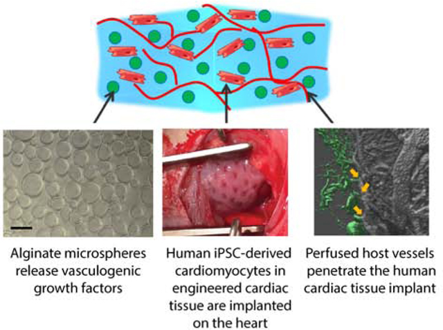
To address this challenge, we have developed a hybrid biomaterial-cell system leveraging host vascular cell responses to initiate and instruct angiogenesis into an implanted engineered cardiac tissue. Our ultimate goal is to achieve functional recovery of the heart through integration and vascularization of implanted engineered cardiac tissue. Our approach consists of embedding alginate microspheres in aligned hiPSC-derived cardiac tissues to deliver a cocktail of angiogenic factors stimulating recruitment and morphogenesis of host endothelial cells in the implant. The pro-angiogenic therapy is here optimized first in vitro to provide maximum synergy between physical cues from microspheres surfaces and biochemical stimulation of endothelial cells. We evaluate efficacy of vascularization and global cardiac function after engineered tissue implantation in a rat model of ischemia/reperfusion myocardial infarction. Our results show for the first time the beneficial effects of integrating cardiac engineered tissues with a localized angiogenic therapy. With this combined therapy, we are able to induce the formation of new functional and perfused vessels in the implanted cardiac tissue, the revascularization of the ischemic heart, and the improvement of whole heart function.
2. Methods
2.1. Cell culture
Primary human umbilical vein endothelial cells (HUVECs) and normal human dermal fibroblasts (NHDF) were supplied by EssenBioScience and cultured in Growth Medium and Complete Assay Medium (EssenBioScience) for the 2D network formation assay.
For the 3D angiogenesis assay, HUVECs were purchased from Lonza (C2519A), expanded and cultured in EGM-2 SingleQuots Kit media (Lonza). The cell medium was changed every 3 days. HUVECs below passage 6 were used for all the in vitro experiments.
Cardiomyocytes were differentiated from hiPSCs in chemically defined conditions following established methods with slight modifications [35, 36] and were used for producing cardiac engineered constructs between day 14 and day 21 of differentiation.
2.2. Production of alginate microspheres
Alginate microspheres were formed using Var J1 bead generator (Nisco, Switzerland). Briefly, 1% (w/v) alginate (Sigma Aldrich) in PBS was mixed with the desired concentration of growth factors, then the solution was extruded by a syringe pump (flow rate= 18mL/h) in a 0.15M CaCl2 bath. The assisted use of a coaxial nitrogen flow (P= 100 mbar) during extrusion allows the production of microspheres with average diameter of 70 μm [17]. After preparation, microspheres were filtered using cell strainers with 40 μm porosity, washed twice with distilled water and immediately used for the release studies or for the preparation of engineered constructs.
2.3. In vitro biotin-VEGF release studies
To quantify the release of growth factors from alginate microspheres, VEGF (Life Technologies) was biotinylated (biotin-VEGF) with ProtOn biotin labeling kit (Vectors Laboratories), according to the manufacturer’s suggested protocol. 1% alginate microspheres loaded with 4 μg of biotin-VEGF were produced and incubated in dH2O up to 3 days. At each time point (1h, 8h, 1 day, 3 days and 7 days), 200 μL aliquots of the incubation solutions were taken and frozen at −80 °C until processed for western blot analysis. Equal amounts of samples per lane were separated on custom-made 12% SDS-polyacrylamide (Tris/glycine) gels and transferred to Nitrocellulose membranes (Bio-Rad). After transfer, IRDye infrared dye-labeled Streptavidin (Li-Cor, 925–32230) was used to detect biotin in the test samples. Blots were scanned with Li-Cor Odyssey Clx Infrared Scanner, and ImageJ software (NIH, Bethesda, MD) was used for quantification of bands density. A water control was included on every blot for normalization.
2.4. Two-dimensional network formation assay
The two-dimensional network formation assay was performed using Essen BioScience CellPlayer Angiogenesis PrimeKit, containing early passage normal human dermal fibroblasts (NHDF) and early passage normal human endothelial cells (HUVECs) transfected with CytoLight Green. NHDF were seeded in 96-well plates and left at room temperature for 1h, according to the manufacturer’s indications. HUVECs were subsequently plated onto NHDF, cells were allowed to settle for 1h at room temperature, then the plate was transferred in the Essen BioScience Incucyte for live cell imaging. After 2 days of culture in the Growth Medium (Essen BioScience, CellPlayer Angiogenesis PrimeKit), cells were treated with 150 μL/well of Complete Assay Medium (Essen BioScience, CellPlayer Angiogenesis PrimeKit) containing control (no growth factors added) and test materials as follows: bFGF in low (4ng/mL) and high (10 ng/mL) concentrations, VEGF in low (4ng/mL) and high (10 ng/mL) concentrations, and combinations of bFGF and VEGF in low (4ng/mL bFGF and 4ng/mL VEGF) and high (10 ng/mL bFGF and 10 ng/mL VEGF) concentrations.
Wide field images of each well were acquired every 3 hours, up to 10 days. Incucyte ZOOM software was used to assess angiogenesis by quantification of fraction network number, area, length, width and number of branch points.
2.5. Three-dimensional angiogenesis assay
Collagen type I from rat tail was purchased from Advanced BioMatrix or extracted from rat tails following a well-established protocol [37] with slight modifications. Briefly, collagen fibers were dissected from rat tail tendons and dissolved for 72 hours in 0.1% acetic acid at 4°C. The solution was centrifuged (12,000 xg) to remove undissolved tissue fragments. Extracted collagen was then precipitated in NaCl, pelleted by centrifugation (12,000 xg), and redissolved in 0.1% acetic acid. Collagen concentration was determined by lyophilization. The production of engineered constructs was performed with either commercial and extracted collagen, and no significant changes were observed in terms of cell viability, compaction of collagen matrix and endothelial network formation when using the two different collagen sources.
For the production of hydrogels and engineered tissues, collagen was diluted to obtain a 2.5 mg/mL solution, and pH was adjusted to 7 – 7.4 with 1M NaOH. Collagen solution was mixed with HUVECs suspended in EBM2, to obtain a final collagen concentration of 1.25 mg/mL and a cell density of 1×10⁶ HUVECs/mL. To track HUVECs morphogenesis in the scaffolds, cells were treated with the green fluorescent CellTracker™ Green BODIPY® Dye (Thermo Fisher) according to the supplier protocol prior to immobilization in the collagen scaffolds.
Alginate microspheres containing different doses of growth factors were incorporated to the collagen-cells mixture in low (50 mg of microspheres/mL of collagen) or high (100 mg of microspheres/mL of collagen) densities. The test conditions included single, double and triple combinations of bFGF, SHH and VEGF (0.67 μg/mL of 1% alginate) loaded in the microspheres. Alginate microspheres were mixed into liquid collagen with cells to form constructs by casting them in untreated 96-well plates with 30 μL of gel/cell/microspheres mix per well. Constructs were left to gel at room temperature for 1 h, then they were incubated at 37°C and culture medium was changed every other day. Samples having growth factors-loaded microspheres were cultured in bFGF- and VEGF- free EGM2 medium, while samples with dispersed unloaded microspheres were cultured either in in bFGF- and VEGF- free EGM2 media (Lonza) and complete EGM2 media (Lonza), as positive and controls, respectively.
Fluorescence imaging was performed with Nikon Eclipse Ti-E inverted microscope, up to 7 days. For quantification, a Cell Profiler [38] code was specifically set up to analyze multiple images. For each iteration, a binary network mask was obtained and networks were identified applying an intensity mask. Network area, number and length were quantified from the intensity mask using Skeletonize3D and Analyze Skeleton Plugins in ImageJ [39].
2.6. Aortic ring assay
All the animal procedures were conducted in accordance with the US NIH Policy on Humane Care and Use of Laboratory Animals and the Brown University Institutional Animal Care and Use Committee (IACUC, protocols No. 1310000025 and 1702000256). The aortic ring assay was performed following Aplin et al. and Zorzi et al. protocols [40, 41], with slight modifications. Briefly, male Sprague Dawley rats (Charles River), wild type genotype, with average weight of 300 – 350g (8–12 weeks old), were sacrificed by heart excision and exsanguination under 4% isoflurane. The descending aorta was dissected, cleaned from fat tissue and cut into 1–2 mm thick rings, that were serum-starved overnight in serum-free EBM2 medium. The rings were embedded in 180 μL of acellular collagen gel (1.25 mg/mL) mixed with 50 mg/mL alginate microspheres releasing double and triple combinations of VEGF, bFGF, and SHH in medium (0.67 μg/mL of alginate) and high concentrations (1.34 μg/mL of alginate).
Cell migration and network formation were evaluated by bright field microscopy up to 7 days. For immunofluorescent staining, the rings embedded in the collagen – alginate microspheres gels were cultured on 50 mm glass Petri dishes. At day 5, gels were treated with 0.02 mg/mL Texas red tomato lectin (Vector Laboratories) in PBS for 10 minutes, fixed with 4% paraformaldehyde (Sigma Aldrich) for 10 minutes at 4°C and imaged as whole-mounts with Olympus FV-1000-MPE Multiphoton Microscope. Z-stack images of the endothelial cells labeled with Texas red tomato lectin were acquired every 2 microns to study the 3-dimensional morphology and spatial organization of the newly formed networks.
2.7. Morphological and functional assessment of engineered cardiac tissues
Cardiac constructs were formed by mixing 1.25 mg/mL collagen, 50 mg/mL alginate microspheres and 33×106 hiPSC-derived cardiomyocytes/mL and allowing them to gel at T=37°C for 1h. Cardiomyocyte morphology and function were assessed in constructs containing unloaded or VEGF- loaded alginate microspheres (0.5 μg/mL and 4 μg/mL). Histology was performed by fixing the constructs in 4% PF, de-hydrating them in 30% sucrose in PBS and by embedding them in frozen blocks using OCT® polymer. 20 μm thick frozen sections were cut with Leica CM3050S cryostat and stained with picrosirius red-fast green and cardiac troponin T (cTnT) to visualize collagen and cardiomyocytes. Acellular scaffolds were produced as control, and microspheres were immersed in 100 μL/mL alcian blue for 5 minutes prior to gel formation, to visualize the microspheres in the frozen sections.
Functional activity of cardiomyocytes in the collagen – alginate microsphere constructs was performed by mechanical analysis at day 7 and 30 of culture. Passive and active mechanical properties of cardiac tissues were measured with a Small Intact Muscle Apparatus (model 801C, Aurora Scientific). Tissue strips were mounted on two hooks (attached to a force transducer and motor arm), bathed in Tyrode’s solution at 34°C, and electrically field stimulated. Force exerted by the tissue was measured with a 5 mN load cell (Aurora Scientific). Tissues were initially stretched to L0, determined as the shortest length at which individual contractions could be detected by the force transducer. The tissues were then stretched by steps of 5% L0 to 30% stretch. Once at 30% stretch, tissues underwent a force-frequency protocol wherein they were consecutively paced at increasing frequencies and the fastest frequency they could follow was measured and recorded as the maximum capture rate (MCR). The force frequency protocol was not run on constructs that broke off the mechanics hooks during the length step process. The following calculations were made based on the data obtained from mechanical testing. Active stress, σa, was determined at each length by averaging the amplitude of twitch force, Fa, of at least 5 contractions after stress relaxation due to the length step had reached a plateau and normalizing by the cross-sectional area (CSA), assumed to be elliptical with depth equal to 0.5 width (measured optically through the microscope). Upstroke velocity was measured by calculating the change in force over time between the minimum and maximum amplitude of at least 5 contractions for each length step, and the time to 50% relaxation (T50) and 90% relaxation (T90) were calculated by locating the time to reach 50% and 90% of the difference between peak and minimum force output for at least 5 contractions at each length step.
Stiffness of each tissue strip was calculated by plotting the passive stress produced by each tissue against the strain. Passive stress, σp, was calculated by normalizing the passive (or baseline) force produced by the tissue at each step, Fp, by the CSA and is reported in units of kPa. Strain, εx, at each step, Lx, was determined as (Lx – L0)/L0. A near-linear relationship of these data allowed for a regression line to be fit to each stress vs. strain plot, and the stiffness (Young’s modulus) is reported as the slope of the line for each tissue.
2.8. Implantation of the engineered constructs in infarcted rat hearts
All animal experiments were conducted according to the U.S. NIH Policy on Humane Care and Use of Laboratory Animals and the Brown University IACUC. Male and female Sprague Dawley athymic nude rats (Charles Rivers), with an average weight of 218g ± 30g (8–12 weeks old), received a myocardial infarct by ischemia/reperfusion, following the procedure described in detail previously [16]. Echocardiography was performed 3–4 days post myocardial injury with a GE Vivid 7 Dimension ultrasound system equipped with a pediatric 10S 4–10 MHz transducer probe (General Electrics), with mild sedation (isoflurane 1.5% - 2%) to avoid suppression of cardiac function and heart rate. Images were obtained in systole and diastole from longitudinal- and short-axis views of the left ventricle at the apical level.
The rats meeting the inclusion criterion (fractional shortening ≤ 45%) were randomly distributed in four groups: (1) sham implants, (2) engineered constructs with only cardiomyocytes (CM), (3) engineered constructs with CM and 50 mg/mL unloaded alginate microspheres and (4) engineered constructs with CM and 50 mg/mL alginate microspheres loaded with 4μg of VEGF, 4μg of bFGF and 4μg of SHH. The cardiac constructs were prepared the same day of the implant (day 4 post MI, Figure 4A) as follow: 1.25 mg/mL collagen was mixed with 8 mg/mL fibrinogen, 20 U aprotinin, 5 μL of 200 U/mL thrombin and a cell suspension of 7–10 ×106 hiPSC-derived cardiomyocytes in PBS to a final volume of 720 μL. The constructs were allowed to gel at 37°C for 1h in a PDMS mold appositely designed to adapt to the rat left ventricle and to recapitulate the fiber orientation of the ventricular wall (Figure 4B and C) [16]. To embed the loaded or unloaded alginate microspheres, these were added to the collagen-cells mixture prior to casting and gelling. All of the procedures were conducted with sterile techniques.
For implantation, the cardiac constructs were positioned over the myocardium and sutured with three 7–0 polypropylene sutures (VP702X, Surgipro II, Covidien), as we previously described 16. Rats received buprenorphine (0.01–0.05 mg/kg) on the day of surgery and 2 days post-surgery, or a single injection of Buprenorphine SR™ (0.8 – 1.2 mg/kg) administered preoperatively. Heart function was monitored weekly after implantation by echocardiography measurements. Rats were sacrificed at 7 days or 1 month post implantation by pentobarbital overdose (180 mg/kg) or exsanguination for vascular perfusion, then the heart was excised and fixed in 4% PF overnight.
2.9. Histological assessment of the explanted tissues
Twenty-three (23) explanted rat hearts were sectioned into transverse slices (short axis) with thickness of 1 mm (Zivic Instruments). For each heart, sections at the papillary level were analyzed to quantify infarct area by picrosirius red-fast green staining, and sections between 1 mm (section 2) and 5 mm (section 5) from the apex were used for evaluating cardiomyocyte morphology (cTnT and α-actinin), tissue engraftment at 7 and 30 days by cTnT staining, macrophage infiltration (CD68), and vessel counts (RECA-1 and αSMA). Vessel count by blinded analysis was performed by 4 researchers on n= 3 (engineered constructs with unloaded microspheres group) or 4 (sham, engineered constructs with cells only and loaded microspheres groups) heart samples. For each heart, vessels stained with Reca-1 and identified with a full circular lumen were counted in the remote, infarct and implant regions in two different heart sections (usually the second and third sections from the apex at 2 mm and 3 mm, respectively, or in more basal sections if cardiac implants were not visible in more apical sections). To assess variability between researchers, vessel count analysis of one heart section per group was performed by 2 different researchers and no differences found.
2.10. Qualitative evaluation of vessels perfusion by Texas Red-tomato lectin
Four (4) hearts were perfused with Texas Red-tomato lectin (Vector Laboratories) at sacrifice. Short-axis thick slices were cut with a vibrating microtome after embedding the hearts in 7% agar, up to a maximum thickness of 400 μm. Sections were then cleared with Visikol® HISTO reagents to acquire images with a florescence microscope (Nikon Eclipse Ti-E inverted microscope) and to create 3D reconstructed images using confocal z-stacks (Olympus FV3000 Confocal Microscope).
2.11. Quantification of angiogenesis by Microfil® perfusion followed by microCT imaging and 3D reconstruction of perfused vasculature
Microfil® (Flow Tech, Carver, MA) perfusion was performed as previously described [42] at sacrifice on a subset of hearts (n= 2 sham, n= 2 engineered constructs with only cardiomyocytes, n= 2 engineered tissues with unloaded microspheres, and n= 5 engineered tissues with growth factors-loaded microspheres). After Microfil® polymerization and overnight fixation in 4% PF, hearts were imaged by microcomputed tomography (microCT; Scanco vivaCT 40) with isotropic voxel dimensions of 10×10×10 μm. MicroCT images were cross-registered with picrosirius red-fast green histological images to identify remote, infarct and implant regions. 3D reconstructions of the z-stacks and vessel tracing by blinded analysis were obtained with IMARIS and Vesselucida 360 software, respectively, and Vesselucida Explorer automated vessels analysis has been used to quantify number of vessels, vessels length, surface area, volume, diameter, tortuosity and number of branch points in each region of interest.
2.12. Statistical Analysis
Statistical difference between groups was evaluated with one-way and two-way analysis of variance (ANOVA), followed by post-hoc Tukey’s or Bonferroni’s test. P <0.05 was considered statistically significant.
3. Results
3.1. VEGF is released from alginate microspheres over 3 days
Monodispersed populations of alginate microspheres, with average diameter of 70 μm, were produced based on the optimization of processing parameters and characterization of varying microspheres formulations as we previously reported [17]. The release of biotinylated growth factor (biotin-VEGF) provides high sensitivity for detection by Western blotting (≥ 5 ng of protein detectable via biotin) and allows precise definition of the release profile from alginate microspheres. The loading dose of the growth factor is within the range used for cell treatments. Results show an initial burst release of biotin-VEGF (50% released at 8 h) and a subsequent sustained release phase, lasting for at least 72 h. No protein was detected in the incubation solution after 7 days (168 hours) of incubation (Figure 1A,B). Because physical interactions, such as ionic bonds, entanglement and other steric effects, are the forces regulating growth factor retention in alginate microspheres, diffusion is the primary driving force for growth factor/morphogen release [43]. The release profile of VEGF from alginate microspheres that we have measured with the Western Blot assay is comparable to the release profiles of growth factors measured in other studies [44, 45] that indicate a 3–7 days release from alginate hydrogels, and our previous study in microspheres using α-chymotrypsin [17].
Figure 1. In vitro VEGF, bFGF and SHH signaling affects endothelial cells plasticity in 2D and 3D assays.

A) Representative blot for biotinylated VEGF released from 1% (w/v) alginate microspheres incubated in dH2O. B) The cumulative release profile was measured from blot optical density and expressed in arbitrary units. C) Wide field fluorescence image of 2D network formation for green-labeled HUVECs treated with VEGF (10ng/mL) and b-FGF (10ng/mL) at 7 days. The red box indicates the area showed in D. D) Skeleton mask applied on image C), to determine the number of networks, number of branch points and network length. Scale bars = 900 μm. (E) Wide field florescence image of 3D network formation assay for green-labeled HUVECs treated with VEGF (0.67μL/mL of alginate) at day 3, scale bar= 300 μm. (F) Network mask applied on image E), to measure network width and area. (G) Network number, area and length measured in HUVECs cultured on top of NHDFs on tissue culture plastic for up to 10 days. Red bars indicate the day of media change and refreshing of growth factor. At 150 hours (~6 days), one-way ANOVA with post-hoc Tukey’s test (*p<0.05, **p<0.01, ***p<0.001) shows 10 ng/mL VEGF + 10 ng/mL bFGF (dark blue curve) is significantly larger than multiple other treatment groups (shown by color-coded asterisks). Colored symbols indicate the statistical significance between VEGF + bFGF high group (dark blue curve) and VEGF low (pink), bFGF low (light green) and VEGF + bFGF low (light blue). Quantification of 3D network formation assay: (H) number and (I) area of endothelial networks measured at 1 day of culture from network intensity masks. Network number and area are relative to the negative control (samples cultured in EGM2 media without VEGF and b-FGF). One-way analysis of variance (ANOVA) followed by Bonferroni post-test was used to determine significance against positive (*p<0.05, **p< 0.01 and *** p<0.001) and negative (#p<0.05, ##p< 0.01 and ###p<0.001) controls, i.e. samples cultured in EGM2 or EGM2 without VEGF and b-FGF, respectively.
3.2. VEGF, bFGF and SHH enhance endothelial network formation in 2D and 3D environments
In a 2-dimensional vascular network formation assay, human umbilical vein endothelial cells (ECs) cultured over a monolayer of neonatal human dermal fibroblasts (NHDF) were used to inform the concentration and combination of growth factors to use in the alginate microspheres (Figure 1C-G). Low (4 ng/mL) and high (10 ng/mL) bFGF and VEGF doses were selected from previous works as they have been shown to induce proliferation and morphogenesis of endothelial cells in vitro [46]. Growth factors induced changes in EC morphology and their reorganization into network-like structures as early as 1 day of culture, while no evidence of network formation was observed for the negative control (with no growth factors added in the culture medium). Network area, network length, number of networks and number of branch points increased in the first 2 days of culture for each of the tested formulations compared to the negative control and were maintained until the end of the experiment (day 10). While no significant increase in network formation was observed by increasing the amount of VEGF from 4 ng/mL to 10 ng/mL, a minimum dose of 10 ng/mL of bFGF was required to promote endothelial cells re-organization in network-like structures (Figure 1F and Supplemental Figures S1 and S2). Furthermore, when treating endothelial cells with bFGF and VEGF in combination, an improved network area and length resulted (Figure 1G). Network width was not affected by growth factor treatment and declined slightly throughout the experiment, suggesting remodeling of the network structures that stabilize at 10 – 20 μm in diameter (Supplemental Figures S1 and S2).
Based on the results of the 2D network formation assay, we selected 10 ng/mL as the target dose of each of VEGF and bFGF to be released from the alginate microspheres within the first day to induce angiogenesis. To isolate the effects of combinatorial growth factor stimulation on ECs (without stromal cells), a 3D network formation assay is used where ECs and microspheres are embedded in a collagen gel (1.2 mg/mL) and assessed through 7 days of culture. Alginate (1% w/v) is mixed with 0.67 μg/mL bFGF and 0.67 μg/mL VEGF to provide a daily release of at least 10 ng/mL and 20 ng/mL when embedding microspheres in low and high density, respectively, over at least 3 days. Further, sonic hedgehog (SHH), a morphogen known to regulate multiple angiogenic cytokines involved with arteriogenesis, capillary formation in wound healing, and remodeling of blood vessels [47, 48], is included (loading dose= 0.67 μg/mL) to support endothelial network maturation and stabilization. ECs immobilized in the collagen-microspheres scaffolds re-organize in the three-dimensional matrix, create cell-cell contacts, and establish network structures in the first day of culture, consistent with the peak release of growth factors from alginate microspheres. While no significant changes are observed in the number of formed networks for any single, double, or triple growth factor combination versus complete EGM2 medium (positive control; Figure 1H), network area and length is increased by the local release of growth factors (Figure 1I and Supplemental Figures S1 and S2). Interestingly, angiogenesis, quantified as the increase of network area and length, is enhanced in some of the formulations, most notably the triple combination of VEGF, bFGF, and SHH released from 50 mg/mL alginate microspheres compared to the positive control (complete EGM2 culture medium). The average length of the networks formed in the 3D gels was 63.60 ± 8.85 μm, with a maximum measured network length of 835.60 μm (Supplemental Figure S1). The use of low density of microspheres (50 mg/ml) dispersed in the collagen gels, loaded with double and triple combination of growth factors, results in an enhanced angiogenic response. Notably, the 3D EC-only assay (lacking stromal cells) shows peak network formation at day 1 followed by a pruning phase of the newly formed EC networks from day 3 to the end of the experiment, day 7 (Figure 1I).
3.3. Heterocellular outgrowth from aortic rings is stimulated by growth factor-releasing alginate microspheres
We use the aortic ring assay in a defined collagen type 1 gel to validate and expand the results obtained with the 2D and 3D network assays in an ex vivo environment with heterogeneous native vascular cell populations. The morphogenic effects of the growth factors released from microspheres embedded in the collagen are assessed by cell migration distance from the aortic rings over 7 days (Figure 2A). Cells from the aortic rings are able to invade the 3D collagen-microspheres gel starting from 1 day of culture (Figure 2B and 2C), and their morphology appears similar to that of the more traditional aortic ring assays performed on Matrigel (Figure 2B) [49]. Maximum coverage (≥ 80% of the available area) is reached at day 7 for most of the growth factor-loaded test conditions (Figure 2D). Similar to the results of the 3D network formation assay, significant differences (p<0.05) are observed in cell sprouting and morphogenesis when compared to the negative control (no bFGF and VEGF added in EGM2 media). The release of double or triple combination of growth factors provides comparable vascularization to the unloaded positive control cultured in complete EGM2 medium (Figure 2D). Because different cell types (including endothelial cells, smooth muscle cells, pericytes, macrophages and fibroblasts) are present in the aortic ring preparation, Texas red tomato lectin is used to bind to the endothelial glycocalyx to confirm the presence and pattern of ECs in the sprouting cells. Z-stacks acquired by confocal microscopy reveal the 3-dimensional network of ECs emanating from the aortic ring into the collagen gel (Figure 2E).
Figure 2. Host endothelial cells invade the collagen-alginate microspheres scaffolds and organize in tubular structures in the aortic ring assay.

A) Endothelial cell migration from the aortic ring was measured at 8 locations around the ring and averaged across ≥3 replicates. Scale bar= 500 μm. Formation of endothelial networks in a control gel matrigel (B) compared to the collagen-alginate microspheres scaffold (C). Alginate microspheres are indicated with yellow arrows. Scale bars= 100 μm. D) Migration length increased for multiple double- and triple-combinations of VEGF (V), bFGF (F), and SHH (S) at high (h) and medium (m) concentrations. E) Host endothelial cells were labeled with Texas red tomato lectin, and the 3-dimensional tube organization was evaluated at day 5 by multiphoton z-stack imaging. The ring is identified with a star. Scale bar= 100 μm.
3.4. Engineered cardiac tissue function is preserved with VEGF-releasing microspheres
Because the goal of this work is to utilize growth factor-releasing microspheres in an implanted cardiac patch to stimulate host vascularization, we also test the effect of VEGF-releasing microspheres on the functional performance of engineered cardiac tissue in vitro to determine if growth factor release impacts tissue mechanics. Cardiac tissues are formed with 2×10⁶ hiPSC-derived cardiomyocytes (average cardiomyocyte purity was 50.42 ± 4.14% by flow cytometry for cardiac troponin T) in a collagen gel with unloaded control, VEGF (0.5 μg/mL), or high VEGF (4 ug/mL) loaded microspheres and cultured for four weeks. Microspheres are mixed with the gelling cardiac construct and show homogeneous dispersion after gel formation (Supplemental Figure S3). Tissues in all groups similarly compact the collagen matrix (Figure 3A) with no statistical significance across groups at each time point up to 30 days (end of experiment). Maximum compaction occurs within 4–5 days after casting. Tissues form a beating syncytia (Supplemental Movie M1), indicating that microsphere inclusion alone or VEGF release from embedded microspheres do not inhibit tissue formation and electrical connectivity of hiPSC-derived cardiomyocytes.
Figure 3. Human iPSC-derived cardiomyocyte engineered tissues function mechanically with microspheres and VEGF inclusion.

(A) Compaction of engineered tissues. The inset represents a cardiac tissue containing VEGF-loaded (4 μg) alginate microspheres at 7 days of culture. (B) Stiffness (Young’s modulus) of engineered tissues. (C) Peak active force at 1 Hz stimulation (*P<0.05). Bars report mean ± SEM, open and solid symbols indicate data measured at 7 and 30 days of culture, respectively, for each test group.
Mechanics analysis at one and four weeks demonstrates a significant decrease in stiffness of unloaded microsphere tissues from 0.230 ± 0.049 kPa to 0.068 ± 0.023 kPa, and a significant increase in high VEGF-loaded microsphere tissues from 0.281 ± 0.098 kPa to 1.159 ± 0.264 kPa (Figure 3B). The modulus of the high VEGF-loaded group is also significantly higher in comparison to the other microsphere groups, but not the collagen control (0.403 ± 0.088 kPa for collagen, 0.068 ± 0.023 kPa for unloaded, and 0.414 ± 0.111 for low VEGF microspheres). Peak active stress, the active twitch force normalized by cross-sectional area as analyzed at 15% stretch, is not different across groups at one and four weeks except in high VEGF loaded microsphere tissues at week 4 (Figure 3C). Further, relaxation time T50 increases in the high VEGF loaded group at 4 weeks, suggesting increased contractile work with high VEGF at late time points with little effect on excitability as measured by maximum capture rate (Supplemental Figure S4). The mechanical characteristics of these engineered hiPSC-derived cardiomyocyte tissues are within the same magnitude that we have reported by our group previously [50–52] and other engineered hiPSC-CM tissues [53–57].These data suggest that transient VEGF release had little influence on the mechanical function of hiPSC-derived cardiomyocytes in engineered tissues.
3.5. Release of growth factors from cardiac constructs promotes neovascularization in the implants and improves heart function in a rat model of myocardial infarct.
Myocardial infarct is induced by occluding the left anterior descending coronary artery for 60 minutes of ischemia followed by reperfusion in 46 athymic Sprague Dawley rats. Of the 37 rats surviving the infarct, 23 meet exclusion criteria for reduced cardiac function (%FS < 45%) and are included in this study (Figure 4A). Large cardiac constructs (2 × 1.5 cm) are implanted on the epicardial surface of the left ventricle 4 days after infarct. Customized constructs with diamond-shape anisotropic posts and cut corners (Figure 4B-E) are used to match the circumferential orientation of the epicardial fibers of the left ventricle and for ease of surgical positioning with the heart’s apex [16]. HiPSC-CMs are dense and uniformly distributed throughout the tissue, showing striations (Figure 4C,D). Animals included in this study (34 ± 8% fractional shortening; Table 1, Figure 4F and Supplemental Figure S5) are randomized into 4 groups, receiving 1) sham implants, 2) engineered cardiac constructs (10 ×106 hiPSC-CMs in a collagen-fibrin hydrogel) 3) engineered cardiac constructs with embedded unloaded alginate microspheres and 4) engineered cardiac constructs containing VEGF (4 μg), b-FGF (4 μg) and SHH (4 μg) loaded microspheres. The dose of growth factors to be immobilized in alginate microspheres has been selected considering the amount of protein lost during hydrogel production, the release profiles of alginate microspheres, the results of the in vitro screening, and the average area of the infarcts (Figures 1–3). Based on our calculations, the microspheres provide a release of at least 200 ng of proteins every day for the first 3 days after implantation.
Figure 4. Release of proangiogenic growth factors from engineered cardiac constructs improve cardiac function.

A) Experimental design of rat surgery and functional, histological and morphological evaluation. B) Cardiac tissue are designed with diamond-shaped internal features and cut corners, for optimal alignment of cardiomyocytes with the epicardial fibers of the left ventricle, scale bar= 1cm. C) cTnT staining (DAB) of hiPSC-CMs immobilized in the construct after preparation (day 0) shows homogeneous dispersion of the cells in the construct, scale bar= 0.5 cm. D) After 7 days of in vitro culture, hiPSC-CMs show elongated and striated morphology, scale bar= 30 μm. The image on the right shows the dashed white square at higher magnification. E) The constructs are implanted 4 days after myocardial infarction (post MI) over the scar and surrounding healthy tissue. F) Echocardiographic evaluation of heart function, measured as the variation of % fractional shortening (%FS) at 3 days post MI versus 1 month after implantation surgery. Two-way ANOVA test shows significance (# P<0.05 compared to the unloaded group post MI and *P<0.05 and **P<0.01 compared to the sham group at 30 days). G) Infarct area measured at 30 days at the papillary muscles level by quantification of the red-stained fibrotic scar in the left ventricle. Inter-individual shape differences are eliminated by normalizing the infarct area to the total area of the left ventricle.
Table 1.
Number, weight and heart function of rats enrolled in the study
| n | Weight (g) | % FS baseline§ | % FS post MI* | % MI/LV areaǂ | |
|---|---|---|---|---|---|
| Sham | 8 | 225 ± 37 | 57 ± 3 | 42 ± 3 | 26 ± 4 |
| Cells only | 4 | 225 ± 38 | 55 ± 7 | 39 ± 6 | 25 ± 8 |
| Microsph - unloaded | 5 | 214 ± 32 | 61 ± 7 | 34 ± 8* | 36 ± 6 *,# |
| Microsph - loaded | 6 | 212 ± 29 | 65 ± 7 | 42 ± 3 | 34 ± 3 * |
% Fractional shortening before myocardial infarction
% Fractional shortening 3 days after myocardial infarction
% Infarcted left ventricle area/Total left ventricle area* p<0.05 compared to the sham group
p<0.05 compared to the cells-only group
The weight of the animals, heart function before and 3 days after infarct (but before construct implantation) and the infarct size at sacrifice was not significantly different among groups (Table 1 and Figure 4E). All explanted hearts show scar formation with some myocardial sparing as expected with reperfusion (Supplemental Figure S4). Functional measurements assessed by echocardiography show a decrease in % fractional shortening (%FS) over time in the sham group, as opposed to the increasing trend exhibited by animals receiving hiPSCs-cardiac implants. Cardiac function is significantly higher in the groups implanted with the cardiac engineered tissues containing alginate microspheres, with 30.5% and 34.3% fractional shortening increase and 14.34% and 18.6% ejection fraction increase for unloaded and loaded microspheres respectively, compared to the sham group at 30 days (Figure 4D and Supplemental Figure S5). Other dimensional parameters (heart rate, interventricular septum thickness, left ventricular internal diameter and anterior wall thickness at end diastole and end systole) do not show significant functional changes for different groups at 30 days post implantation (Supplemental Figure S5). Both male and female rats were enrolled in this study.
Survival and retained spatial structural organization of the engineered constructs, manifested as the presence of elongated and aligned hiPSC-derived cardiomyocytes, is evident at 7 and 30 days post implantation (Figure 5A-E; Supplemental Figure S6). Measure of viable cardiac tissue in the implants (quantified as the area occupied by cTnT positive cells from histological images) indicate an average of 42% and 50% engraftment by area for unloaded and loaded groups respectively at day 7, that is maintained for the unloaded and loaded groups at 30 days (p>0.05) (Figure 5B). Minimal compaction of the construct on day 0 may cause an underestimation of engraftment by area quantification. Histological assessment of explanted hearts shows characteristic changes due to ischemia, including cTnT depletion in the scar and the presence of macrophages in the scar compared to the remote myocardium (Figure 5C-H). Macrophage infiltration into the implant may be enhanced by the presence of alginate microspheres, where CD68-positive cells localized (Figure 5G (arrows) and Supplemental Figure S6).
Figure 5. Release of growth factors from alginate microspheres promotes cell viability up to 30 days.

A) Picrosirius red-fast green staining on whole cross-sections of the heart show a well-integrated implant (cardiac engineered tissue with loaded microspheres), scale bar = 1mm. B) Quantification of hiPSC-cardiac tissue engraftment by cTnT positive area measurements at 7 and 30 days, normalized to the hiPSC-CMs area measured in implants at day 0 (evaluated with the same histological method to compare area after 7, 30 days to initial area). C) Cardiac troponin T and different cardiomyocytes density in the healthy (1), infarct (2) and implant (3) regions at 7 days post MI (scale bar= 1mm). Cardiomyocytes structure and organization are visible at lower (D, scale bars= 100 μm) and higher (E, scale bars = 30 μm) magnification, with striations in the remote region and aligned cardiomyocytes in the implant. Microspheres are indicated with black arrows. G) Macrophages, stained with CD68, are visible in the infarct and in the cardiac tissues at 1 week post implantation. Scale bars= 100 μm.
Angiogenesis and neovascularization is robust in the cardiac tissues containing unloaded and loaded alginate microspheres, while poor vascular integration is observed in the grafts containing only hiPSC-derived cardiomyocytes. Host endothelial cells penetrate the collagen-alginate microspheres scaffolds and formed capillary-like structures in close proximity to alginate microspheres, as shown with RECA-1 staining (Figure 6A-B). Recruitment of αSMA-positive cells to larger vessel-like structures suggests stabilization of arteriole-sized (20 – 100 μm) neovessels in the implants (Supplemental Figure S7). Notably, a 1.6- fold increase in vessel density is observed in the implants containing growth factors-loaded microspheres, compared to the unloaded controls at 30 days post implant (Figure 6C). In addition, vessel development and persistence are promoted in the infarct region of the experimental group treated with growth factors, as a more dense vasculature is present in the infarct zone of this treatment group with respect to the infarcted tissues of animals receiving engineered tissues with cells only or cells with unloaded microspheres (Figure 6C). The presence of alginate microspheres (either loaded or unloaded) may shift the distribution of vessel diameter in the implants towards larger (40 μm) vessels, as shown in the histograms of Supplemental Figure 7D. Texas red tomato lectin perfusion via the aorta prior to sacrifice enabled our initial identification of host vessels invading the engineered tissues (Figure 6D), confirming perfusion of these penetrating vessels.
Figure 6. Host endothelial cells invade the collagen-alginate microspheres cardiac scaffolds and promote angiogenesis in the implant and infarct scar.

A) Implanted heart stained by picrosirius red (pink) and fast green (green) and RECA-1 enable identification of (1) remote, (2) infarct and (3) implant regions. The implant is demarcated with the red dashed line. RECA-1 (DAB, brown) staining of endothelial cells in remote, infarct and implant regions at 1 month post MI show vessel density and morphology for an implanted construct containing unloaded alginate microspheres (harvested 30 days after implantation). The black debris visible in vessel lumens is residual Microfil® post-processing. B) Images at higher magnification show healthy endothelial cell phenotypes in the remote and implant areas, with thin endothelial cells lining lumenal structures and/or microspheres. In contrast, morphologically round cells visible in the infarct (black arrows) are indicative of the presence of macrophages phagocytizing cells expressing RECA-1. Scale bars = 30 μm. C) Quantification of vessels density in the remote area (R), infarct (I) and implant (Imp). An average of 1510 ± 252, 809 ± 140 and 592 ± 113 vessels were counted in R, I and Imp regions of interest, respectively. Two-way ANOVA test indicates statistical significance (*P<0.05 and **P<0.01). D) Texas red tomato lectin perfusion of a healthy rat heart shows vessels originating from the host that invade the collagen/alginate microspheres scaffold. Voids (arrows) may represent microspheres locations.
Patent blood vessels in healthy, infarct and cardiac tissues are assessed by Microfill® perfusion at sacrifice followed by microcomputed tomography (microCT) analysis and 3-dimensional reconstruction of the vasculature (Figure 7 and Supplemental Figure 8). Automated 3D analysis of networks traced in the implant volumes shows increased number of perfused vessels in the engineered tissues containing growth factors-loaded alginate microspheres (p<0.05 compared to the cells only control group) and presence of larger vessels with higher number of branches with respect to the engineered tissues containing unloaded alginate microspheres (Figure 7 B-D). The average diameter of traced vessels is 41. 67 ± 13.61 μm, 37.99 ± 3.00 μm and 37.45 ± 5.96 μm for implants containing cells only, unloaded and loaded microspheres, respectively, with more than 90% of the invading vessels exhibiting diameters in the range of 20 – 100 μm (Figure 7E).
Figure 7. In vivo perfusion and 3D image reconstruction are used to visualize ingrowth of vessels from the host to the cardiac constructs and to quantify multiple angiogenic metrics.

(A) Microfil® is perfused via the aorta in the heart vasculature (I). Samples are then scanned through microCT. By cross-registering histological images (II) with microCT z-stacks (III), the volumes occupied by the infarct scar tissue (red) and by the implant (yellow) are segmented, as shown in (IV). 3D reconstruction of heart vasculature is obtained with IMARIS software (V) and identification of the vasculature invading the engineered tissues is identified in green (VI). Images at higher magnifications (VII) allow identification of the origin of the vessels penetrating in the implant (indicated by the yellow arrows). (VIII) 3D reconstruction of vessels present in the cardiac constructs are traced with Vesselucida360 software (IX) and processed through Vesselucida Explorer software (X-XI) for automated analysis. The image in X shows a representative pool of vessels (networks 1 through 4) with varying diameters and total length. Branching nodes are highlighted in red. Segments are defined as any portion of vessel between two branching nodes and are labeled (I, II, III) in network 1 (blue vessel) as an example. Panels B-G show multiple angiogenic metrics quantified with automated analysis of 3D-reconstructed vessels in implant volumes. n= 184 vessels were identified and analyzed for implants containing only cardiomyocytes (cells only), n= 371 for implants containing unloaded alginate microspheres and n= 1858 for implants loaded with alginate microspheres releasing 4μg VEGF, 4μg bFGF and 4μg SHH.
The different shape and dispersion of the violin plots displaying number of network segments, surface area, volume and length indicate a slight though not statistically significant increase of vascular density in the therapeutic implants providing localized release of growth factors (Supplemental Figure S8). Typically, larger vessels give rise to more branches (Figure 7F), and the linear regression between vessel diameter and number of branch nodes becomes stronger for the growth-factors loaded implants compared to the cells only and unloaded controls (R2 = 0.39, 0.53 and 0.84 for cells only, unloaded and growth-factors loaded groups, respectively). This suggests that more complex network structures form, better resembling the architecture of the native vascular tree. Furthermore, the tortuosity index (defined as the ratio of the actual curved length of the segment over the linear distance between the endpoints of the segment) is significantly lower in the vessels developing in the engineered tissues containing loaded alginate microspheres compared to the other groups, indicating decreased complexity, twisting and distortion of the network paths (Figure 7G).
4. Discussion
The main goal of this study was to demonstrate the efficacy of integrating proangiogenic drug delivery with cardiac tissue engineering in a clinically relevant ischemia/reperfusion model of myocardial infarction. Because of the mass of transplanted tissue and growing metabolic needs of maturing hiPSC-derived cardiomyocytes, we hypothesized that localized angiogenic factor release would increase the density of perfused vessels in the engineered tissue, resulting in better tissue integration and whole heart function in vivo. In this study, we deliver hiPSC-CMs in engineered tissues that also contain alginate microspheres loaded with angiogenic factors VEGF, bFGF, and sonic hedgehog. Upon careful analysis of the vascular density in 2D and 3D, we confirm that perfused vessel density is increased in the implanted engineered tissue (Figures 6–7). Moreover, 3D analysis reveals longer vessel segments with greater branching, a wider distribution of vessel diameters, and reduced tortuosity, suggesting that a more hierarchical, straight vasculature forms with our angiogenic-cardiac tissue co-therapy (Figure 7).
The ability of biomaterials to sequester, localize, and release biologics such as proteins has been broadly demonstrated [43]. In the setting of revascularization therapies for cardiac repair, multiple groups have shown improved vascularization and heart function by various 2D metrics at 1–4 weeks [2, 24, 58]. Through sequestration and protection of the protein biologics from degradation, a controlled release strategy improves the otherwise short biological half-life of angiogenic growth factors following intravenous or intracoronary administration [59, 60]. While some literature suggests that prolonged release of growth factors, over weeks or even months, could be beneficial for the formation of stable vascular networks [45, 61], it is clear that unregulated and continuous expression of VEGF in the heart leads to deleterious side effects in vivo, such as the formation of vascular tumors resembling hemangiomas [62]. Our data demonstrates a temporally restricted 3-day release profile (Figure 1B). VEGF and bFGF have been included in our angiogenic therapeutic as they are critical factors for angiogenesis and vasculogenesis during embryo development and have shown synergistic effects on revascularization in the adult [63–65], while SHH is a morphogen that is activated early in the embryo to promote 3D organization and stability of the newly formed vessels [66, 67]. We found that the benefits of VEGF and bFGF delivery were additive in 2D in vitro vascularization assays, and addition of sonic hedgehog (SHH) in 3D modified aortic ring vascularization assays with VEGF and/or bFGF provided robust vessel growth responses (Figures 1, 2). Our approach for localized delivery within the implanted engineered tissue shows a robust vascular response in both the implant and the infarct region of the left ventricle (Figures 6C and 7). Alginate has been widely used as biomaterial for cardiac regeneration, and injectable or implantable alginate hydrogels have been previously used as drug or cell delivery systems to the MI. Enhanced left ventricle remodeling and cardiac function has been observed by Landa et al [68], following intramyocardial injection of alginate biomaterials. Ceccaldi et al showed that cardiac G-type alginate implants loaded with mesenchymal stem cell exhibit higher structural and mechanical properties after implantation [69]. Furthermore, we have recently demonstrated that delivering immunomodulatory cues in the MI via in situ gelling- alginate hydrogels promote a local phenotypic change in the immune cell population, facilitating the initiation of healing processes [70].
Microsphere incorporation and VEGF release had overall little effect on engineered cardiac tissue formation and function (Figure 3). The size of microspheres relative to the engineered hiPSC-CM tissues (approximately 17 mm x 3 mm) formed for compatibility with our mechanical analysis apparatus may displace cardiomyocytes and interfere with cell-cell adhesions during formation. While we did see a significant increase in stiffness at 4 weeks in the high-VEGF group, we did not see similarly significant increases in active stress or contraction kinetics (Figure S3). Regular media changes every other day in vitro likely impacted the release and exposure of our engineered hiPSC-derived cardiomyocyte tissues to VEGF. Further studies need to be performed to see what specific pathways VEGF may be influencing the cells in the engineered tissues. Literature suggests VEGF and its downstream signaling pathways may improve cardiac contractility through a positive inotropic response in L-type calcium channels [71–73]. The mechanical parameters of our tissues are comparable with those of other cardiac tissue engineering groups in both contractile strength and kinetics [53–55, 57, 74] after normalization for cross-sectional area and could be improved in future studies by purification and metabolic maturation of the input cardiomyocytes [75].
Transplantation of hiPSC-derived cardiomyocytes in engineered tissues on the epicardium with our biomaterials-driven angiogenic therapy improves whole heart function versus sham treatment (Figure 4F), which appears similar to results shown by other groups [4, 6–9, 15, 54, 76]. However, our work alone targets both cardiomyocyte engraftment and vascularization as a dual-pronged approach to heart regeneration therapy and demonstrates efficacy with smaller sample size. The significant improvement of cardiac function that we observe after implantation of the unloaded collagen/alginate microspheres constructs (Figure 4F) could derive partially from mechanical and biological effects induced in the infarct by the biomaterials. Implantation or injection of acellular biomaterials in the MI has been previously demonstrated to alter local stress profiles, with normalized ventricular stress distribution, and to reduce myocardial dilatation [77, 78]. Furthermore, alginate biomaterials are known to induce localized changes in the immune and inflammatory cell populations, possibly facilitating reparative and pro-angiogenic processes [70, 79]. Although we demonstrate some functional recovery with our treatments, a major limitation of this study and many others remains the persistence of a fibrotic scar in the infarcted region (Figure 4F), that might lead to adverse tissue remodeling [80]. To overcome this limitation, other groups are working on how to orchestrate regression of scar [81, 82], and our ongoing studies are aimed at integrating the cardiac constructs with novel factors that could better regulate the wound healing process.
Animals receiving the cardiomyocyte-angiogenic factor combined therapy show enhanced host angiogenesis in the engineered tissues and as well as an added beneficial vascularization in the infarct itself, where there is a 49.8% increase in vessel density compared to the unloaded formulations (Figure 6C). The localized release of VEGF, bFGF and SHH was successful in recruiting host-derived neovessels into the implants to increase volumetric vessel density, branching, and diameter of perfused vessels while minimizing tortuosity (Figure 7). The increase in perfused vessels in the cardiac tissue implants is likely due to the local release of the angiogenic factors that we hypothesize create local gradients for stimulating endothelial cells to increase angiogenic sprouting. The long-term stability of these vessels after 1 month supports the well-accepted idea that implanted engineered tissue requires a greater vascular supply [14]. Indeed, our echocardiography data shows evidence of improved cardiac function beyond that observed with cardiomyocytes alone (Figure 4F), justifying the use of the angiogenic factor-loaded microspheres approach in engineered cardiac tissue.
Although we cannot distinguish between a direct effect of released angiogenic factors versus a paracrine effect from implanted cells (or both) as the cause of increased infarct vessel density (Figure 5B), reduced host tissue ischemia likely contributes to functional gains of our novel therapeutic approach. Because the proangiogenic combination delivered in vivo in this study is quickly released from the microspheres by diffusion mechanisms (Figure 1A and 1B), the significant enhancement of cardiac function and angiogenesis at 30 days (Figures 4–7) suggests a successful initiation of a more robust host vascular response to create a durable vascular bed.
While several studies have been recently focusing on promoting angiogenesis in implanted scaffolds and engineered tissues [6, 10, 21, 24, 31, 58], a rigorous, standardized method for quantifying neovessel formation in vivo has not been broadly adopted. Often, quantification protocols rely on immunohistochemical staining of vessels in 2-dimensional thin sections [6, 10, 31]. With this approach, several limitations exist, including little ability to coordinate lumens with a connected and perfused vessel, no ability to assess vessel length/branching/tortuosity. To overcome these limitations, we use a robust method [42] for perfusing vasculature at physiological pressures with radiopaque dye and imaging with microcomputed tomography to assess angiogenesis in 3-dimensional reconstructions of heart samples after 1 month. Only a few studies report 3D measures of density and diameter of vessels in the injured heart using such a perfusion method [42, 83], and we are the first to do this for implanted engineered human cardiac tissue. Our 3D analysis enables quantitative assessment of vessel density and morphology of the entire microvasculature in the engineered tissues implanted on the injured heart. With high spatial resolution (10×10×10 μm3 voxel size), smaller arterioles can be resolved to result in more reliable and accurate measurements of new vessels. Our results demonstrate increased 3D vessel density and diameter, with decreased tortuosity. These results suggest that greater convective blood flow is possible into the engineered tissue due to larger diameter vessels and that a less tortuous vascular bed increases perfusion efficiency.
Conclusions
Restoration of cardiac function utilizing engineered tissue will ultimately require an efficiently perfused vascular bed in the implanted tissue, and here we show that this is feasible through leveraging smart biomaterials to direct host vascularization of implanted engineered human cardiac tissue. This novel platform is efficacious in the setting of myocardial repair post MI and provides a template for developing a diverse array of combinatorial regeneration-revascularization therapies.
Supplementary Material
Highlights:
Heart regeneration requires new muscle, which we deliver with engineered tissue
We created a dual therapy to deliver hiPSC-cardiomyocytes and vasculogenic proteins
Alginate microspheres embedded in the engineered tissue are local protein depots
New vessels perfuse the human cardiac implant at 1 month, shown by 3D analysis
This new dual therapy improves heart function
Acknowledgements
We gratefully acknowledge Sartorius (formerly Essen Bioscience) for providing a demonstration of the IncuCyte ZOOM. We also acknowledge our staff animal surgeon, Collin Polucha, for performing the surgical procedures, and Animal Care Facility at Brown University for animal care. We are grateful to Dr. Ulrike Mende (Rhode Island Hospital) and Dr. Robert Guldberg (University of Oregon) for collaboration, Angela Lin and the Petit Institute for Bioengineering & Bioscience at Georgia Tech for assistance for microCT imaging, and Michelle King for technical assistance with Western Blot analysis.
Sources of Funding: Research reported in this publication was supported by the National Heart, Lung, and Blood Institute of the National Institutes of Health under award numbers R00HL115123 and R01HL135091 (to KLKC) and by the School of Engineering at Brown University. The content is solely the responsibility of the authors and does not necessarily represent the official views of the National Institutes of Health.
Footnotes
Data Availability: The raw/processed data required to reproduce these findings are available from the authors upon request.
Declaration of interests: The authors declare that they have no known competing financial interests or personal relationships that could have appeared to influence the work reported in this paper.
Publisher's Disclaimer: This is a PDF file of an unedited manuscript that has been accepted for publication. As a service to our customers we are providing this early version of the manuscript. The manuscript will undergo copyediting, typesetting, and review of the resulting proof before it is published in its final form. Please note that during the production process errors may be discovered which could affect the content, and all legal disclaimers that apply to the journal pertain.
References
- 1.Hara H, et al. , Discovery of a Small Molecule to Increase Cardiomyocytes and Protect the Heart After Ischemic Injury. JACC: Basic to Translational Science, 2018. 3(5): p. 639. [DOI] [PMC free article] [PubMed] [Google Scholar]
- 2.Ruvinov E, Leor J, and Cohen S, The promotion of myocardial repair by the sequential delivery of IGF-1 and HGF from an injectable alginate biomaterial in a model of acute myocardial infarction. Biomaterials, 2011. 32(2): p. 565–578. [DOI] [PubMed] [Google Scholar]
- 3.Lancaster JJ, et al. , An electrically coupled tissue-engineered cardiomyocyte scaffold improves cardiac function in rats with chronic heart failure. The Journal of Heart and Lung Transplantation, 2014. 33(4): p. 438–445. [DOI] [PMC free article] [PubMed] [Google Scholar]
- 4.Zimmermann WH, et al. , Engineered heart tissue grafts improve systolic and diastolic function in infarcted rat hearts. Nat Med, 2006. 12(4): p. 452–8. [DOI] [PubMed] [Google Scholar]
- 5.Lam MT and Wu JC, Biomaterial applications in cardiovascular tissue repair and regeneration. Expert review of cardiovascular therapy, 2012. 10(8): p. 1039–1049. [DOI] [PMC free article] [PubMed] [Google Scholar]
- 6.Wendel JS, et al. , Functional Effects of a Tissue-Engineered Cardiac Patch From Human Induced Pluripotent Stem Cell-Derived Cardiomyocytes in a Rat Infarct Model. Stem Cells Translational Medicine, 2015. 4(11): p. 1324–1332. [DOI] [PMC free article] [PubMed] [Google Scholar]
- 7.Christoforou N, et al. , Implantation of Mouse Embryonic Stem Cell-Derived Cardiac Progenitor Cells Preserves Function of Infarcted Murine Hearts. PLOS ONE, 2010. 5(7): p. e11536. [DOI] [PMC free article] [PubMed] [Google Scholar]
- 8.Liu Y-W, et al. , Human embryonic stem cell–derived cardiomyocytes restore function in infarcted hearts of non-human primates. Nature Biotechnology, 2018. 36: p. 597. [DOI] [PMC free article] [PubMed] [Google Scholar]
- 9.Weinberger F, et al. , Cardiac repair in guinea pigs with human engineered heart tissue from induced pluripotent stem cells. Science Translational Medicine, 2016. 8(363): p. 363ra148. [DOI] [PubMed] [Google Scholar]
- 10.Riegler J, et al. , Human Engineered Heart Muscles Engraft and Survive Long Term in a Rodent Myocardial Infarction Model. Circulation research, 2015. 117(8): p. 720–730. [DOI] [PMC free article] [PubMed] [Google Scholar]
- 11.Shiba Y, et al. , Human ES-cell-derived cardiomyocytes electrically couple and suppress arrhythmias in injured hearts. Nature, 2012. 489(7415): p. 322–5. [DOI] [PMC free article] [PubMed] [Google Scholar]
- 12.Romagnuolo R, et al. , Human Embryonic Stem Cell-Derived Cardiomyocytes Regenerate the Infarcted Pig Heart but Induce Ventricular Tachyarrhythmias. Stem Cell Reports, 2019. 12(5): p. 967–981. [DOI] [PMC free article] [PubMed] [Google Scholar]
- 13.van Laake LW, et al. , Human embryonic stem cell-derived cardiomyocytes and cardiac repair in rodents. Circ Res, 2008. 102(9): p. 1008–10. [DOI] [PubMed] [Google Scholar]
- 14.Ogle BM, et al. , Distilling complexity to advance cardiac tissue engineering. Science translational medicine, 2016. 8(342): p. 342ps13–342ps13. [DOI] [PMC free article] [PubMed] [Google Scholar]
- 15.Ye L, et al. , Cardiac Repair in a Porcine Model of Acute Myocardial Infarction with Human Induced Pluripotent Stem Cell-Derived Cardiovascular Cells. Cell Stem Cell, 2014. 15(6): p. 750–761. [DOI] [PMC free article] [PubMed] [Google Scholar]
- 16.Munarin F, et al. , Laser-Etched Designs for Molding Hydrogel-Based Engineered Tissues. Tissue Engineering. Part C, Methods, 2017. 23(5): p. 311–321. [DOI] [PMC free article] [PubMed] [Google Scholar]
- 17.Munarin F. and Coulombe KLK, A Novel 3-Dimensional Approach for Cardiac Regeneration. Conference proceedings: … Annual International Conference of the IEEE Engineering in Medicine and Biology Society. IEEE Engineering in Medicine and Biology Society. Annual Conference, 2015. 2015: p. 1741–1744. [DOI] [PMC free article] [PubMed] [Google Scholar]
- 18.Jackman CP, et al. , Engineered cardiac tissue patch maintains structural and electrical properties after epicardial implantation. Biomaterials, 2018. 159: p. 48–58. [DOI] [PMC free article] [PubMed] [Google Scholar]
- 19.Sekine H, et al. , Endothelial Cell Coculture Within Tissue-Engineered Cardiomyocyte Sheets Enhances Neovascularization and Improves Cardiac Function of Ischemic Hearts. Circulation, 2008. 118(14 suppl 1): p. S145–S152. [DOI] [PubMed] [Google Scholar]
- 20.Callegari A, et al. , Neovascularization induced by porous collagen scaffold implanted on intact and cryoinjured rat hearts. Biomaterials, 2007. 28(36): p. 5449–5461. [DOI] [PubMed] [Google Scholar]
- 21.Kreutziger KL, et al. , Developing vasculature and stroma in engineered human myocardium. Tissue engineering. Part A, 2011. 17(9–10): p. 1219–1228. [DOI] [PMC free article] [PubMed] [Google Scholar]
- 22.Zieber L, et al. , Microfabrication of channel arrays promotes vessel-like network formation in cardiac cell construct and vascularization in vivo. Biofabrication, 2014. 6(2): p. 024102. [DOI] [PubMed] [Google Scholar]
- 23.Zhang B, et al. , Biodegradable scaffold with built-in vasculature for organ-on-a-chip engineering and direct surgical anastomosis. Nat Mater, 2016. 15(6): p. 669–678. [DOI] [PMC free article] [PubMed] [Google Scholar]
- 24.Miyagi Y, et al. , Biodegradable collagen patch with covalently immobilized VEGF for myocardial repair. Biomaterials, 2011. 32(5): p. 1280–1290. [DOI] [PubMed] [Google Scholar]
- 25.Chu H, et al. , A [polycation:heparin] complex releases growth factors with enhanced bioactivity. Journal of Controlled Release, 2011. 150(2): p. 157–163. [DOI] [PubMed] [Google Scholar]
- 26.Moroni F. and Mirabella T, Decellularized matrices for cardiovascular tissue engineering. American Journal of Stem Cells, 2014. 3(1): p. 1–20. [PMC free article] [PubMed] [Google Scholar]
- 27.Gershlak JR, et al. , Crossing kingdoms: Using decellularized plants as perfusable tissue engineering scaffolds. Biomaterials, 2017. 125: p. 13–22. [DOI] [PMC free article] [PubMed] [Google Scholar]
- 28.Richardson TP, et al. , Polymeric system for dual growth factor delivery. Nat Biotech, 2001. 19(11): p. 1029–1034. [DOI] [PubMed] [Google Scholar]
- 29.Perets A, et al. , Enhancing the vascularization of three-dimensional porous alginate scaffolds by incorporating controlled release basic fibroblast growth factor microspheres. Journal of Biomedical Materials Research Part A, 2003. 65A(4): p. 489–497. [DOI] [PubMed] [Google Scholar]
- 30.Hosseinkhani H, et al. , Enhanced angiogenesis through controlled release of basic fibroblast growth factor from peptide amphiphile for tissue regeneration. Biomaterials, 2006. 27(34): p. 5836–5844. [DOI] [PubMed] [Google Scholar]
- 31.Riemenschneider SB, et al. , Inosculation and perfusion of pre-vascularized tissue patches containing aligned human microvessels after myocardial infarction. Biomaterials, 2016. 97: p. 51–61. [DOI] [PMC free article] [PubMed] [Google Scholar]
- 32.Bargehr J, et al. , Epicardial cells derived from human embryonic stem cells augment cardiomyocyte-driven heart regeneration. Nature biotechnology, 2019. 37(8): p. 895–906. [DOI] [PMC free article] [PubMed] [Google Scholar]
- 33.Stoker ME, Gerdes AM, and May JF, Regional differences in capillary density and myocyte size in the normal human heart. Anat Rec, 1982. 202(2): p. 187–91. [DOI] [PubMed] [Google Scholar]
- 34.Kaneko N, et al. , Three-dimensional reconstruction of the human capillary network and the intramyocardial micronecrosis. American Journal of Physiology - Heart and Circulatory Physiology, 2011. 300(3): p. H754. [DOI] [PubMed] [Google Scholar]
- 35.Burridge PW, et al. , Chemically Defined and Small Molecule-Based Generation of Human Cardiomyocytes. Nature methods, 2014. 11(8): p. 855–860. [DOI] [PMC free article] [PubMed] [Google Scholar]
- 36.Lian X, et al. , Robust cardiomyocyte differentiation from human pluripotent stem cells via temporal modulation of canonical Wnt signaling. Proceedings of the National Academy of Sciences of the United States of America, 2012. 109(27): p. E1848–E1857. [DOI] [PMC free article] [PubMed] [Google Scholar]
- 37.Eschenhagen T, et al. , 3D engineered heart tissue for replacement therapy. Basic Research in Cardiology, 2002. 97(1): p. I146–I152. [DOI] [PubMed] [Google Scholar]
- 38.Kamentsky L, et al. , Improved structure, function and compatibility for CellProfiler: modular high-throughput image analysis software. Bioinformatics, 2011. 27(8): p. 1179–1180. [DOI] [PMC free article] [PubMed] [Google Scholar]
- 39.Arganda-Carreras I, et al. , 3D reconstruction of histological sections: Application to mammary gland tissue. Microscopy Research and Technique, 2010. 73(11): p. 1019–1029. [DOI] [PubMed] [Google Scholar]
- 40.Aplin AC, et al. , Chapter 7 The Aortic Ring Model of Angiogenesis, in Methods in Enzymology. 2008, Academic Press. p. 119–136. [DOI] [PubMed] [Google Scholar]
- 41.Zorzi P, et al. , Technical Advance: The rat aorta contains resident mononuclear phagocytes with proliferative capacity and proangiogenic properties. Journal of Leukocyte Biology, 2010. 88(5): p. 1051–1059. [DOI] [PMC free article] [PubMed] [Google Scholar]
- 42.Weyers JJ, et al. , Retrograde Perfusion and Filling of Mouse Coronary Vasculature as Preparation for Micro Computed Tomography Imaging. Journal of Visualized Experiments : JoVE, 2012(60): p. 3740. [DOI] [PMC free article] [PubMed] [Google Scholar]
- 43.Li J. and Mooney DJ, Designing hydrogels for controlled drug delivery. Nature reviews. Materials, 2016. 1(12): p. 16071. [DOI] [PMC free article] [PubMed] [Google Scholar]
- 44.Wu H, et al. , Fabrication of core–shell microspheres using alginate and chitosan–polycaprolactone for controlled release of vascular endothelial growth factor. Reactive and Functional Polymers, 2012. 72(7): p. 427–437. [Google Scholar]
- 45.Campbell KT, et al. , Alginate hydrogels allow for bioactive and sustained release of VEGF-C and VEGF-D for lymphangiogenic therapeutic applications. PLOS ONE, 2017. 12(7): p. e0181484. [DOI] [PMC free article] [PubMed] [Google Scholar]
- 46.Bai Y, et al. , Effects of combinations of BMP-2 with FGF-2 and/or VEGF on HUVECs angiogenesis in vitro and CAM angiogenesis in vivo. Cell and Tissue Research, 2014. 356(1): p. 109–121. [DOI] [PubMed] [Google Scholar]
- 47.Pola R, et al. , The morphogen Sonic hedgehog is an indirect angiogenic agent upregulating two families of angiogenic growth factors. Nat Med, 2001. 7(6): p. 706–711. [DOI] [PubMed] [Google Scholar]
- 48.Straface G, et al. , Sonic hedgehog regulates angiogenesis and myogenesis during post-natal skeletal muscle regeneration. Journal of Cellular and Molecular Medicine, 2009. 13(8b): p. 2424–2435. [DOI] [PMC free article] [PubMed] [Google Scholar]
- 49.Nicosia RF, The aortic ring model of angiogenesis: a quarter century of search and discovery. Journal of cellular and molecular medicine, 2009. 13(10): p. 4113–4136. [DOI] [PMC free article] [PubMed] [Google Scholar]
- 50.Rupert CE and Coulombe KLK, IGF1 and NRG1 Enhance Proliferation, Metabolic Maturity, and the Force-Frequency Response in hESC-Derived Engineered Cardiac Tissues. Stem Cells Int, 2017. 2017(1687–966X (Print)): p. 7648409. [DOI] [PMC free article] [PubMed] [Google Scholar]
- 51.Kaiser NJ, et al. , Optimizing Blended Collagen-Fibrin Hydrogels for Cardiac Tissue Engineering with Human iPSC-derived Cardiomyocytes. ACS Biomater Sci Eng, 2019. 5(2): p. 887–899. [DOI] [PMC free article] [PubMed] [Google Scholar]
- 52.Rupert CE, Irofuala C, and Coulombe KLK, Practical adoption of state-of-the-art hiPSC-cardiomyocyte differentiation techniques. PLOS ONE, 2020. 15(3): p. e0230001. [DOI] [PMC free article] [PubMed] [Google Scholar]
- 53.Goldfracht I, et al. , Generating ring-shaped engineered heart tissues from ventricular and atrial human pluripotent stem cell-derived cardiomyocytes. Nature Communications, 2020. 11(1): p. 75. [DOI] [PMC free article] [PubMed] [Google Scholar]
- 54.Shadrin IY, et al. , Cardiopatch platform enables maturation and scale-up of human pluripotent stem cell-derived engineered heart tissues. Nature Communications, 2017. 8(1): p. 1825. [DOI] [PMC free article] [PubMed] [Google Scholar]
- 55.Dwenger M, et al. , Chronic optical pacing conditioning of h-iPSC engineered cardiac tissues. Journal of tissue engineering, 2019. 10: p. 2041731419841748–2041731419841748. [DOI] [PMC free article] [PubMed] [Google Scholar]
- 56.Wang EY, et al. , Biowire Model of Interstitial and Focal Cardiac Fibrosis. ACS Cent Sci, 2019. 5(7): p. 1146–1158. [DOI] [PMC free article] [PubMed] [Google Scholar]
- 57.Mannhardt I, et al. , Automated Contraction Analysis of Human Engineered Heart Tissue for Cardiac Drug Safety Screening. LID - 10.3791/55461 [doi]. (1940–087X (Electronic)). [DOI] [PMC free article] [PubMed] [Google Scholar]
- 58.Awada HK, Johnson NR, and Wang Y, Sequential delivery of angiogenic growth factors improves revascularization and heart function after myocardial infarction. Journal of Controlled Release, 2015. 207: p. 7–17. [DOI] [PMC free article] [PubMed] [Google Scholar]
- 59.Simón-Yarza T, et al. , Vascular Endothelial Growth Factor-Delivery Systems for Cardiac Repair: An Overview. Theranostics, 2012. 2(6): p. 541–552. [DOI] [PMC free article] [PubMed] [Google Scholar]
- 60.Wang Z, et al. , Novel biomaterial strategies for controlled growth factor delivery for biomedical applications. Npg Asia Materials, 2017. 9: p. e435. [Google Scholar]
- 61.Borselli C, et al. , Functional muscle regeneration with combined delivery of angiogenesis and myogenesis factors. Proceedings of the National Academy of Sciences, 2010. 107(8): p. 3287. [DOI] [PMC free article] [PubMed] [Google Scholar]
- 62.Lee RJ, et al. , VEGF gene delivery to myocardium: deleterious effects of unregulated expression. Circulation, 2000. 102(8): p. 898–901. [DOI] [PubMed] [Google Scholar]
- 63.Apte RS, Chen DS, and Ferrara N, VEGF in Signaling and Disease: Beyond Discovery and Development. Cell, 2019. 176(6): p. 1248–1264. [DOI] [PMC free article] [PubMed] [Google Scholar]
- 64.Asahara T, et al. , Synergistic Effect of Vascular Endothelial Growth Factor and Basic Fibroblast Growth Factor on Angiogenesis In Vivo. Circulation, 1995. 92(9): p. 365–371. [DOI] [PubMed] [Google Scholar]
- 65.Drake CJ, et al. , VEGF regulates cell behavior during vasculogenesis. Dev Biol, 2000. 224(2): p. 178–88. [DOI] [PubMed] [Google Scholar]
- 66.Chapouly C, et al. , Role of Hedgehog Signaling in Vasculature Development, Differentiation, and Maintenance. International journal of molecular sciences, 2019. 20(12): p. 3076. [DOI] [PMC free article] [PubMed] [Google Scholar]
- 67.Rivron NC, et al. , Sonic Hedgehog-activated engineered blood vessels enhance bone tissue formation. Proceedings of the National Academy of Sciences of the United States of America, 2012. 109(12): p. 4413–4418. [DOI] [PMC free article] [PubMed] [Google Scholar]
- 68.Landa N, et al. , Effect of Injectable Alginate Implant on Cardiac Remodeling and Function After Recent and Old Infarcts in Rat. Circulation, 2008. 117(11): p. 1388–1396. [DOI] [PubMed] [Google Scholar]
- 69.Ceccaldi C, et al. , Alginate scaffolds for mesenchymal stem cell cardiac therapy: influence of alginate composition. Cell Transplant, 2012. 21(9): p. 1969–84. [DOI] [PubMed] [Google Scholar]
- 70.Bloise N, et al. , Engineering Immunomodulatory Biomaterials for Regenerating the Infarcted Myocardium. Front. Bioeng. Biotechnol, 2020. [DOI] [PMC free article] [PubMed] [Google Scholar]
- 71.Xing LZ, Ni HJ, and Wang YL, Quercitrin attenuates osteoporosis in ovariectomized rats by regulating mitogen-activated protein kinase (MAPK) signaling pathways. Biomed Pharmacother, 2017. 89: p. 1136–1141. [DOI] [PubMed] [Google Scholar]
- 72.Shi L, et al. , Peptide Lv augments L-type voltage-gated calcium channels through vascular endothelial growth factor receptor 2 (VEGFR2) signaling. Biochim Biophys Acta, 2015. 1853(5): p. 1154–64. [DOI] [PMC free article] [PubMed] [Google Scholar]
- 73.Rottbauer W, et al. , VEGF-PLCgamma1 pathway controls cardiac contractility in the embryonic heart. Genes Dev, 2005. 19(13): p. 1624–34. [DOI] [PMC free article] [PubMed] [Google Scholar]
- 74.Zhao Y, et al. , A Platform for Generation of Chamber-Specific Cardiac Tissues and Disease Modeling. Cell, 2019. 176(4): p. 913–927 e18. [DOI] [PMC free article] [PubMed] [Google Scholar]
- 75.Tohyama S, et al. , Distinct metabolic flow enables large-scale purification of mouse and human pluripotent stem cell-derived cardiomyocytes. Cell Stem Cell, 2013. 12(1): p. 127–37. [DOI] [PubMed] [Google Scholar]
- 76.Chow A, et al. , Human Induced Pluripotent Stem Cell-Derived Cardiomyocyte Encapsulating Bioactive Hydrogels Improve Rat Heart Function Post Myocardial Infarction. Stem Cell Reports, 2017. 9(5): p. 1415–1422. [DOI] [PMC free article] [PubMed] [Google Scholar]
- 77.Shuman JA, et al. , Localized targeting of biomaterials following myocardial infarction: a foundation to build on. Trends in cardiovascular medicine, 2013. 23(8): p. 301–311. [DOI] [PMC free article] [PubMed] [Google Scholar]
- 78.Tous E, et al. , Injectable acellular hydrogels for cardiac repair. J Cardiovasc Transl Res, 2011. 4(5): p. 528–42. [DOI] [PubMed] [Google Scholar]
- 79.Singelyn JM, et al. , Naturally derived myocardial matrix as an injectable scaffold for cardiac tissue engineering. Biomaterials, 2009. 30(29): p. 5409–5416. [DOI] [PMC free article] [PubMed] [Google Scholar]
- 80.Sun Y. and Weber KT, Infarct scar: a dynamic tissue. Cardiovascular Research, 2000. 46(2): p. 250–256. [DOI] [PubMed] [Google Scholar]
- 81.Holmes JW, Laksman Z, and Gepstein L, Making better scar: Emerging approaches for modifying mechanical and electrical properties following infarction and ablation. Progress in biophysics and molecular biology, 2016. 120(1–3): p. 134–148. [DOI] [PMC free article] [PubMed] [Google Scholar]
- 82.Liang J, et al. , Concise Review: Reduction of Adverse Cardiac Scarring Facilitates Pluripotent Stem Cell-Based Therapy for Myocardial Infarction. Stem Cells, 2019. 37(7): p. 844–854. [DOI] [PMC free article] [PubMed] [Google Scholar]
- 83.Boerckel JD, et al. , Mechanical regulation of vascular growth and tissue regeneration in vivo. Proceedings of the National Academy of Sciences, 2011. 108(37): p. E674. [DOI] [PMC free article] [PubMed] [Google Scholar]
Associated Data
This section collects any data citations, data availability statements, or supplementary materials included in this article.