Abstract
Wall stress is often lower in tissue-engineered constructs than in comparable native tissues due to the use of stiff polymeric materials having thicker walls. In this work, we sought to design a murine arterial graft having a more favorable local mechanical environment for the infiltrating cells; we used electrospinning to enclose a compliant inner core of poly(glycerol sebacate) with a stiffer sheath of poly(caprolactone) to reduce the potential for rupture. Two scaffolds were designed that differed in the thickness of the core as previous computational simulations found that circumferential wall stresses could be increased in the core toward native values by increasing the ratio of the core:sheath. Our modified electrospinning protocols reduced swelling of the core upon implantation and eliminated residual stresses in the sheath, both of which had contributed to the occlusion of implanted grafts during pilot studies. For both designs, a subset of implanted grafts occluded due to thrombosis or ruptured due to suspected point defects in the sheath. However, there were design-based differences in collagen content and mechanical behavior during early remodeling of the patent samples, with the thinner-core scaffolds having more collagen and a stiffer behavior after 12 weeks of implantation than the thicker-core scaffolds. By 24 weeks, the thicker-core scaffolds also became stiff, with similar amounts of collagen but increased smooth muscle cell and elastin content. These data suggest that increasing wall stress toward native values may provide a more favorable environment for normal arterial constituents to form despite the overall stiffness of the construct remaining elevated due to the absolute increase in load-bearing constituents.
Impact statement
Differences in the mechanical stimuli experienced by cells in tissue-engineered constructs from those found in their native environment contribute to long-term neotissue formation and remodeling. In this study, we used electrospinning to fabricate bilayered arterial vascular grafts with different geometries but identical microstructures to understand the potential for the initial mechanical state to influence long-term matrix and cellular composition. We found that increased circumferential stress in the inner layer of the graft associated with a more native-like tissue composition.
Keywords: tissue-engineered vascular graft, circumferential wall stress, mechanical behavior, poly(glycerol sebacate), electrospinning, scaffold design
Introduction
Many challenges to arterial tissue engineering remain to be addressed. Animal models have been essential for evaluating biomaterials and studying neotissue formation, yet persistent limitations must be overcome to have confidence in the associated outcomes. For example, small-caliber grafts, particularly those used in murine models, have an increased propensity for thrombosis compared with large diameter grafts, while potential rupture remains a concern in arterial applications. Several approaches have been taken to reduce the frequency of these failure modes. For thrombosis, the use of anticoagulants has been widespread, such as oral administration or biomaterial surface functionalization with heparin.1,2 Yet, anticoagulants can affect neotissue deposition and remodeling, which could weaken the emerging vessel structure.3
To protect against rupture, the scaffolds are often designed to be thicker than the native blood vessel,4 with slow degrading, stiff polymers meant to allow adequate formation of neotissue before the loss of scaffold integrity.5 Both of these precautions can cause stress shielding of the mechanosensitive cells within the developing neotissue, reducing the loads experienced during matrix deposition and remodeling, which in turn affects the material stiffness of the neovessel. Furthermore, many synthetic polymers used for in situ tissue engineering are semicrystalline and hydrolysable,6 which engender a sigmoidal loss of mechanical integrity.7 These polymers create two periods of remodeling in the grafts. Most scaffold material remains during early times, degrading slowly and reducing the load experienced by cells and the newly deposited material. Then, at later times, the polymer begins to degrade at an accelerated rate, often faster than neotissue can be deposited or remodeled by cells, leading to dilatation and potential rupture.
With recent advances in fabrication technologies, there has been a drive not only to prevent graft failures by occlusion and rupture, but also to improve the long-term functional behavior of the tissue-engineered vascular grafts (TEVGs).8,9 The early profile of cellular infiltration and matrix production is mediated primarily by the foreign body response, including macrophages that can undergo phenotypic modulation in response to hemodynamic cues.10 At longer times, native vascular mechanobiology begins to play an increasing role in graft evolution as smooth muscle cells accumulate.11 Thus, to improve TEVG function at longer times, initial scaffold design should anticipate the native mechanobiology. Motivated by the layered structure of the native arterial wall, multilayered vascular grafts have been implanted, although with varying success.12 It is crucial, therefore, to understand the differences that arise in the loads experienced in each layer of these grafts from those normally seen in the arterial wall.13 In the native wall, the medial layer bears most of the load under normotensive conditions, while the adventitia engages with the onset of higher blood pressures to protect the fragile smooth muscle cells of the media from excessive stress. In contrast, in most bilayered vascular grafts, a compliant inner layer is surrounded by a stiffer sheath that generally stress shields the core under physiological hemodynamic conditions. Computational studies have provided new insights into the mechanical14 and structural15 considerations for tissue-engineered cardiovascular scaffolds. Simulations aiming to quantify circumferential stresses in bilayered arterial scaffolds show that the thickness of each layer can dramatically affect the mechanobiological stimuli on the infiltrating cells.16
This article examines in vivo efficacy in a murine model of bilayered tubular scaffolds consisting of a fast-degrading, elastomeric core and a slow-degrading, stiffer sheath. Two different scaffolds were designed with different thicknesses of the core layer to examine potential effects of changing geometries on the long-term composition and mechanical properties of the evolving TEVG. To this end, a previous electrospinning protocol12 for poly(glycerol sebacate) (PGS) was modified to improve its utility for preclinical studies. An outer sheath of electrospun poly(caprolactone) (PCL) was added to provide overall structural support during neotissue formation in the core. Grafts were implanted as a murine infrarenal aortic interposition model, and their failure modes, long-term structure, and load bearing were evaluated to understand the potential of this approach for arterial tissue engineering.
Methods
Scaffold fabrication and characterization
Fabrication of the core
PGS prepolymer (pPGS) was synthesized in-house using previously reported methods.17 Namely, pPGS was blended with polyvinyl alcohol (PVA, generously provided by Soarus, LLC) at a 55:45 mass ratio and dissolved at 16% w/v in hexafluoroisopropanol (HFIP, Oakwood Chemical). The polymer blend was then electrospun at 55 μL·min−1 from a 22G needle spinneret charged to +12 kV. To form the electric field, a second electrode was charged to −12 kV and positioned 50 cm from the needle. Electrospinning was at room temperature and 40% relative humidity. Fibers were collected on a rotating stainless-steel mandrel (diameter of 0.64 mm, 100 rpm) positioned 30 cm from the spinneret. To facilitate scaffold removal after electrospinning, the mandrel was coated with 1% hyaluronic acid (HA; Sigma-Aldrich) to prevent direct contact with polymer fibers. A digital micrometer (LS-7070M; Keyence) was used to monitor the fiber accumulation process to achieve targeted core thickness of the two designs. The fibrous pPGS/PVA cores were dried under vacuum for at least 12 h before crosslinking at 120°C under vacuum for 48 h. The crosslinked cores on the mandrels were stored under vacuum until application of the PCL sheath.
Application of the sheath
PCL (Sigma-Aldrich ; Mn = 80,000) was dissolved in a 5:1 v/v blend of trifluoroethanol (Acros Organics): MilliQ water at 14% w/v. The PCL solution was electrospun at 29 μL·min−1 from a 22G needle spinneret charged to +12 kV. To form the electric field, a stainless-steel plate was used as the second electrode, charged to −12 kV, and positioned 40 cm from the spinneret. Electrospinning was performed at room temperature and 34% relative humidity. The mandrel with PGS/PVA core was positioned 30 cm from the spinneret, grounded, and rotated at 80 rpm. Electrospun PCL fibers were drawn from the plate to the core, forming a tightly packed sheath. Sheathing continued until its thickness reached 25 μm. To release prestress of PCL fibers, the bilayered tubular scaffolds were annealed while on the mandrels at 50°C under 1 atm for 30 min.
Removal of PVA carrier
To isolate the bilayered scaffold, the mandrel was immersed in water to dissolve the HA coating. Scaffolds were then gently removed from the mandrel and cut into 7 mm lengths. These grafts were washed vigorously in MilliQ water at 37°C with orbital rotation at 200 rpm to remove PVA carrier. Eight hours of washing was applied to the grafts with frequent fresh water replenishment. Finally, transmural flow of water was achieved in each graft by injecting water through the lumen. The graft was then gently washed in MilliQ water overnight, followed by lyophilization for storage in desiccant.
PVA quantification
Thermal properties of the PGS/PVA cores were examined using differential scanning calorimetry (DSC) analysis (DSC Q200; TA instruments) to quantify the PVA content. Specifically, 7–9 mg of the core sample was packed into an aluminum pan with a cover, and the test was performed in a heat/cool/heat model under a nitrogen atmosphere with a flow rate of 50 mL·min−1. The temperature was first increased to 180°C, cooled to −75°C, and raised again to 250°C at 10°C·min−1. The area under the PVA melting peak (∼170–180°C) from the second heating cycle was integrated using the manufacturer's software. The scan of pure PGS was flat in that region. A standard curve was constructed from scans of blends of PGS and PVA dissolved at known mass ratios in HFIP, cast into films, and cured under the same conditions as the cores. Samples (n = 3) were taken from each core or standard type.
Scanning electron microscopy
Scaffolds were cut into segments transversely or vertically, mounted onto aluminum stubs to expose the transverse, luminal, or abluminal surfaces, sputter coated with gold, and observed with a field emission scanning electron microscope (SEM, 6330F; JEOL, Tokyo, Japan). PGS core and PCL sheath thickness of the graft were measured from transverse sections. Images from each scaffold design (n = 3) were analyzed to identify the pore size, fiber diameter, and porosity of the PGS core and PCL sheath. Pore sizes and fiber diameters were quantified from 200 × to 2000 × magnification images, respectively. Pore sizes were quantified using a custom MATLAB image segmentation algorithm based on fuzzy C-means clustering. Fiber diameters were quantified using the diameterJ plug-in for ImageJ. Porosity was calculated by using statistical relations derived for fibrous assemblies.18
Graft implantation and testing
Surgical implantation
All animal protocols were approved by the Institutional Care and Use Committee at Nationwide Children's Hospital, and animals received humane care in compliance with the National Institutes of Health (NIH) Guide for the Care and Use of Laboratory Animals. Scaffolds were implanted in 8–10-week-old female C57BL/6 mice. Scaffolds of 0.64 mm diameter and 3 mm length were implanted as infrarenal aortic interposition grafts using the standard microsurgical technique.19 The scaffold diameter was selected to match the size of mouse aorta, with the length to fit in between the renal artery and the iliac bifurcation.20,21 Briefly, a midline laparotomy incision was introduced from below the xyphoid to the suprapubic region, and a self-retaining retractor inserted. The intestines were wrapped in saline-moistened gauze and retracted. The infrarenal aorta and inferior vena cava were bluntly defined. The aorta was separated from the inferior vena cava, vascular control was obtained with microvascular clamps, and the infrarenal aorta was transected. Grafts were anastomosed with 10–0 polypropylene running suture. The skin was closed in two layers using 6–0 black22 polyamide monofilament suture, and the animals were moved to a recovery cage with a warming pad until becoming fully mobile. Upon recovery, the mouse was returned to a new cage, and pain medication (ibuprofen, 30 mg/kg, drinking water) was given for 48 h.22 At the prescribed endpoint, mice were euthanized with a cocktail overdose of ketamine (200 mg/kg) and xylazine (20 mg/kg), and grafts were explanted, including proximal and distal native aorta. Samples were stored in Hank's Balanced Salt Solution on ice and shipped for biaxial mechanical testing as described below.
Biaxial mechanical testing
Composite vessel segments, including the proximal aorta, the tissue-engineered graft, and the distal aorta were explanted at 2, 12, or 24 weeks for biaxial mechanical testing.4 Sutures were placed along the length of the graft and attached aortic segments before explant, and the distance between them was measured before and after removal of the composite. This provided an estimate of the in vivo axial stretch of the graft. Graft segments were cannulated on glass micropipettes using 6–0 suture and placed in a custom computer-controlled biaxial testing device.23 The testing chamber was filled with Hank's Balanced Salt Solution. Vessels were stretched to the estimated in vivo axial stretch and allowed to equilibrate at 80 mmHg for 15 min with physiologic flow conditions. Three cycles of preconditioning were then run from 0 to 120 mmHg, after which the unloaded configuration was measured. The true in vivo axial stretch was found by identifying the stretch at which axial force remained nearly constant for changes in pressure.24 Pressure-diameter tests were reported from 0 to 120 mmHg at the experimentally determined value of in vivo axial stretch.
Histology
Following biaxial mechanical testing, grafts were fixed in 4% paraformaldehyde overnight, serially dehydrated in graded ethanol solution, immersed in xylene, then embedded in paraffin, cut to 5 μm thick sections, and mounted for histological analysis. Samples were analyzed for structural markers with Hematoxylin and Eosin (H&E), Picrosirius Red (PSR), and Hart's Elastin. Cellular stains identified smooth muscle cells (calponin, ab46794) and macrophages (CD68, ab125212). For cellular stains, slides were deparaffinized through xylene and graded ethanol solutions. Endogenous peroxidase was blocked in 3% H2O2 and nonspecific protein binding was blocked using Background Sniper (BioCare Medical, CA). Primary antibody binding was detected by subsequent incubation with species appropriate biotinylated IgG (Vector, CA), followed by streptavidin-horseradish peroxidase (Vector) and chromogenic development with 3,3-diaminobenzidine (Vector). Tissue was counterstained using Gill's Hematoxylin (Vector).25 Images were captured on an inverted microscope (Eclipse Ti, Nikon, Melville, NY) equipped with a digital camera (QImaging, BC, Canada). Quantification of histological images was performed using custom MATLAB scripts, as reported previously.26 The background of each image was subtracted and positive pixels for each stain were isolated and quantified. For immunohistochemical stains, at least four images per graft were taken at 40 × magnification and quantified. For histological stains, the entire vessel wall was imaged and quantified at 20 × magnification, and the quantified pixels were then normalized by the unloaded area of each vessel as determined following mechanical testing.
Statistical analysis
Data were analyzed in the software Prism (Version 7.01) using a two-way analysis of variance with corrections for multiple comparisons. Comparisons were made between each of the graft designs at each time point. Significance was indicated for p < 0.05.
Results
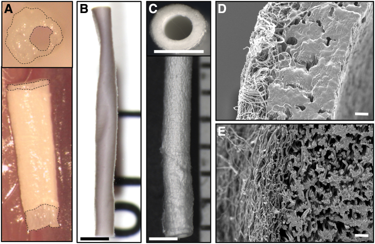
Preliminary attempts to fabricate bilayered scaffolds encountered several challenges. During the initial electrospinning process, drawing of PCL fibers onto a PGS core places the fibers under tension (Fig. 1A). The residual hydrophilic PVA swells upon exposure to aqueous solutions, resulting in complementary processes that often cause the graft to buckle (Fig. 1B). This swelling also caused the ends of the core to protrude from within the sheath when unconstrained axially (Fig. 2A). The combined effects of residual stress in the sheath and swelling of the core led to a wrinkled surface morphology in preliminary studies (Fig. 2B). Hence, the aforementioned high temperature annealing step was added to the postfabrication protocol, which eliminated the surface wrinkling (Fig. 2C). The initial washing method conducted at room temperature with low flow rates swelled the PVA and left minimal porosity (Fig. 2D). Increasing both water flow rate and washing temperature reduced the residual PVA content from 9.50% ± 3.02% to 4.57% ± 1.25% by mass and created a more open porous structure in the graft with less swelling potential (Fig. 2E).
FIG. 1.
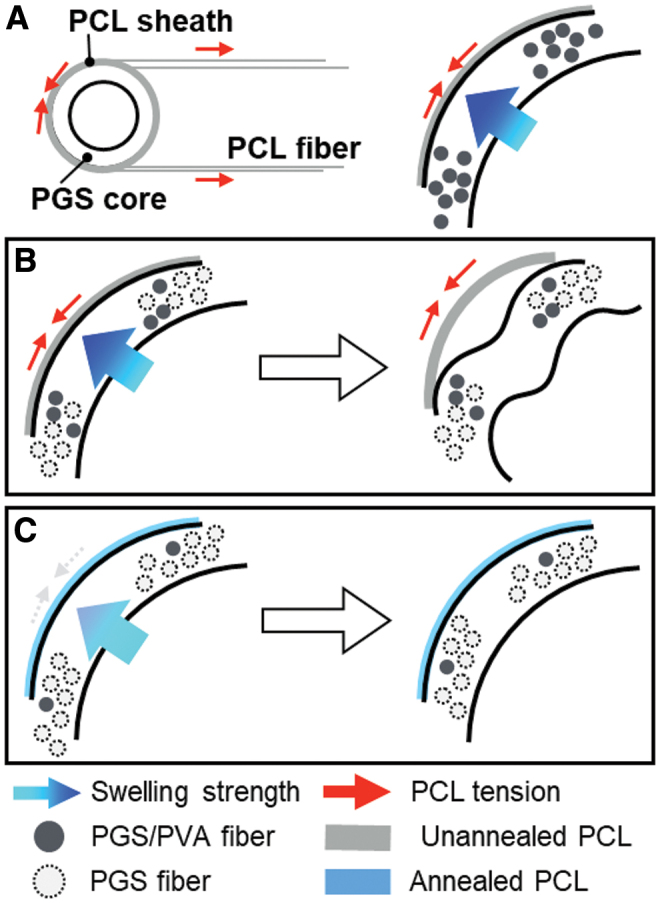
Schematic figure (A) of PCL sheath application (left) and forces involved (right). Prestress and swelling led to a buckling-type deformation of the graft (B), which could be resolved with annealing of PCL and removal of PVA (C). PCL, poly(caprolactone); PVA, polyvinyl alcohol. Color images are available online.
FIG. 2.
(A) A swollen graft showed the asymmetric transverse section (upper) and core protrusion (bottom). An unannealed graft deformed by PCL prestress (B), while an improved fabrication process provided implantable bilayered grafts (C). Imaged using dissecting microscope (scale bar = 1 mm). Transverse sections of grafts with inefficient wash (D) and optimized wash (E) displayed different morphology. Imaged using scanning electron microscopy (scale bar = 10 μm.) Color images are available online.
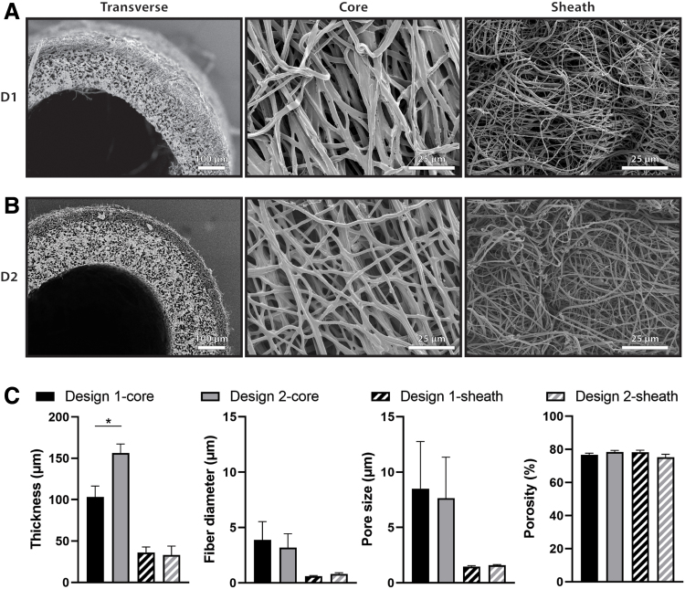
Scaffolds fabricated after the improvements to the electrospinning process were designed to have two different thicknesses for the PGS core layer while maintaining the same PCL sheath thickness and the same microstructure in each layer. Design 1 (D1) scaffolds had thinner cores (Fig. 3A) with a targeted thickness of 100 μm. Measurements from transverse scaffold images taken with SEM showed a D1 core thickness of 103.1 ± 13.4 μm. Design 2 (D2) scaffolds had thicker cores (Fig. 3B) with a targeted thickness of 160 μm. SEM quantification of core thickness for D2 showed a thickness of 156.4 ± 10.8 μm, which was significantly higher than that of D1 (Fig. 3C). The thickness of the PCL sheath for each design was also quantified from SEM as 36.11 ± 6.68 μm and 33.03 ± 10.9 μm for D1 and D2, respectively, which were not significantly different, as desired. Scaffold microstructure was quantified by measuring fiber diameter, pore size, and porosity of the PGS core and PCL sheath (Fig. 3C). The fiber diameter of the PGS core for each design was 3.87 ± 0.15 μm and 3.17 ± 0.16 μm for D1 and D2, respectively. The fiber diameter of the PCL sheath for each design was 0.61 ± 0.05 μm and 0.80 ± 0.11 μm for D1 and D2, respectively. The pore size of the PGS core for each design was 8.51 ± 0.28 μm and 7.64 ± 0.11 μm for D1 and D2, respectively. The pore size of the PCL sheath for each design was 1.46 ± 0.08 μm and 1.58 ± 0.06 μm for D1 and D2, respectively. The porosity of the PGS core for each design was 76.83% ± 0.88% and 78.34% ± 1.04% for D1 and D2, respectively. The porosity of the PCL sheath for each design was 78.27% ± 1.18% and 75.18% ± 1.84% for D1 and D2, respectively. No significant differences were found in microstructure of the core or sheath.
FIG. 3.
Scanning electron microscopic images of Design 1–D1 (A) and Design 2–D2 (B) scaffolds. Transverse sections of the graft (left) show the inner PGS core and outer PCL sheath for both designs. Images of the luminal surface (middle) and abluminal surface (right) show the core fiber morphology and sheath fiber morphology, respectively. (C) Quantification of thickness, fiber diameter, pore size, and porosity of PGS core and PCL sheath of each design. Statistical comparisons indicate p < 0.05 (*). PGS, poly(glycerol sebacate).
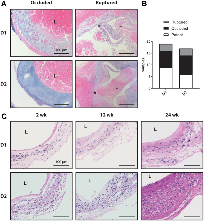
For D1, 19 out of 28 total animals (68%) survived the perioperative period. Of the 19 surviving animals, 7 (37%) occluded from a thrombus and 3 (16%) ruptured due to the failure of the PCL sheath. This left nine surviving animals of which equal numbers were explanted at each of the desired endpoints of 2 (n = 3), 12 (n = 3), and 24 (n = 3) weeks (Fig. 4). For D2, 17 out of 26 total animals (65%) survived the perioperative period. Of the 17 surviving animals, 8 (47%) occluded and 3 (18%) ruptured. The surviving 6 animals were explanted at 2 (n = 1), 12 (n = 2), and 24 (n = 3) weeks (Fig. 4). Carstairs' staining of occluded grafts revealed fibrin-rich thrombus in both designs (Fig. 4A). Ruptured grafts were also stained with Carstairs', and demonstrated local rupture of the wall, which led to thrombus formation on the interior and exterior surface of the grafts (Fig. 4A). H&E staining of the patent grafts showed cellular infiltration by 2 weeks and the continued presence of cells through 24 weeks of remodeling, as well as slight thickening of the graft wall (Fig. 4C).
FIG. 4.
(A) Carstairs' stain of Design 1 and 2 grafts that occluded or ruptured. The lumen of each graft is marked by L and the site of failure in the ruptured grafts is marked by.* (B) Quantification of rupture, occlusion, and patency rates for all implanted Design 1 and 2 Grafts. (C) Cross-sections of patent grafts explanted 2, 12, 24 weeks after implantation are shown for both designs using Hematoxylin and Eosin staining. All scale bars are 100 μm. Color images are available online.
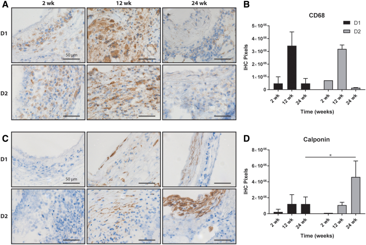
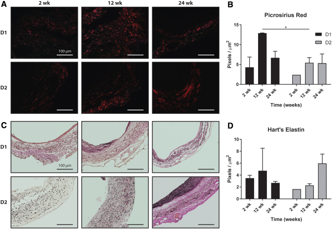
Both graft designs showed similar inflammatory profiles as identified by staining against the macrophage marker CD68 (Fig. 5A). Macrophages were present at 2 weeks, increased substantially at 12 weeks, and then appeared to resolve by 24 weeks (Fig. 5B). No significant differences in inflammation were observed between the two designs at any time point. Few calponin-positive smooth muscle cells (Fig. 5C) were observed in D1 or D2 grafts after 2 weeks, but increased staining was seen in both designs by 12 weeks. D2 grafts showed significantly more calponin staining than D1 grafts after 24 weeks (Fig. 5D). Quantification of collagen from PSR staining showed similar levels of collagen at 2 weeks and increased amounts by 12 weeks; D1 had significantly more collagen at 12 weeks than D2 (Fig. 6A). At 24 weeks, the amount of collagen in D1 had decreased, while the amount of collagen in D2 remained similar to that at 12 weeks. Both designs had similar collagen content at 24 weeks (Fig. 6B). Hart's elastin stain quantified the elastic fibers. Staining at 2 and 12 weeks showed scattered elastin fragments in both designs (Fig. 6C). Although the D2 grafts appeared to have a higher density of elastin at 24 weeks (Fig. 6D), no statistically significant differences in elastin content were found between the designs at any times.
FIG. 5.
(A) IHC staining of pan-inflammatory CD68+ cells (brown) in Design 1 and Design 2 grafts at 2, 12, and 24 weeks postimplantation and (B) the related quantification. (C) Similar IHC staining of calponin and (D) the related quantification. Statistical comparisons indicate p < 0.05 (*). All scale bars are 50 μm. IHC, immunohistochemical. Color images are available online.
FIG. 6.
(A) Picrosirius red staining of fibrillar collagen (red) for Design 1 and Design 2 grafts at 2, 12, and 24 weeks postimplantation and (B) the related quantification. (C) Hart's staining of elastic fibers for Design 1 and Design 2 grafts at 2, 12, and 24 weeks postimplantation and (D) the related quantification. Statistical comparisons indicate p < 0.05 (*). All scale bars are 100 μm. Color images are available online.
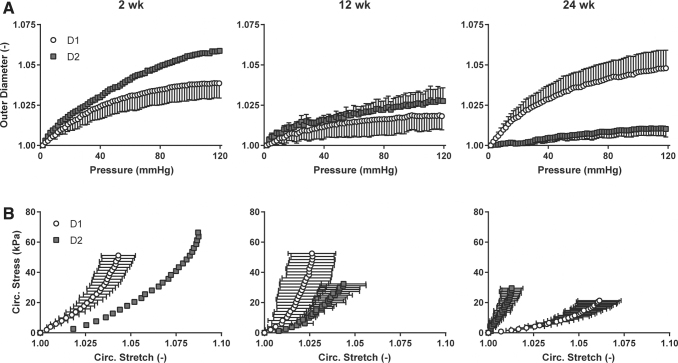
Mechanical testing of D1 and D2 grafts characterized the behavior of the grafts under biaxial loading. The structural stiffness of the remodeling grafts, that is, the mechanical behavior that depends on both geometry and material properties, was quantified by examining changes in outer diameter as a function of changing distending pressure (Fig. 7A). D1 grafts showed increasing structural stiffness from 2 to 12 weeks, followed by a decrease in structural stiffness from 12 to 24 weeks. D2 grafts showed an increasing structural stiffness from 2 to 24 weeks with little distensibility at 24 weeks. Circumferential wall stress/stretch relations revealed the material stiffness of the composite neotissue, that is, the mechanical behavior that depends on the material of which the graft is comprised (Fig. 7B). D1 grafts became slightly stiffer from 2 to 12 weeks, then much more compliant at 24 weeks. D2 grafts increased in stiffness from 2 to 24 weeks, mirroring the structural stiffness data. Because the structural behavior is affected by geometry, the inner diameter and thickness of both graft designs were compared at 24 weeks to determine if the stark mechanical differences at that time could be explained by material differences alone. At 24 weeks, the inner diameter and thickness for D1 grafts were 770.5 ± 308.8 μm and 191.9 ± 5.78 μm; the inner diameter and thickness for D2 grafts were 858.3 ± 198.4 μm and 185.5 ± 35.7 μm, respectively. There was no significant difference in either diameter or thickness at 24 weeks, suggesting that the primary difference between the grafts was the neotissue content and/or organization.
FIG. 7.
(A) Structural stiffness revealed by plots of outer diameter versus pressure for Design 1 and Design 2 grafts at 2, 12, and 24 weeks postimplantation. The diameter values were normalized by the outer diameter values at zero pressure. (B) Material stiffness revealed by circumferential stress versus circumferential stress for Design 1 and Design 2 grafts at 2, 12, and 24 weeks postimplantation.
Discussion
The tissue engineering strategy employed in this work sought to focus on improvements to designing vascular grafts in situ. PGS has shown promise as an alternative to classical tissue engineering materials because of its increased compliance and exponential, rather than sigmoidal, degradation profile.27 The clinical utility of PGS for arterial tissue engineering has been limited, however, by fabrication methods relying on porogens.28,29 These porogens can be difficult to remove for large clinical scaffolds because of diffusion limits or require the use of cytotoxic organic solvents. Nevertheless, grafts from these studies showed positive long-term outcomes,29 and demonstrated that a bilayered design with a PGS core and a PCL sheath could succeed as an arterial conduit. Electrospinning offers a promising alternative to porogen-based methods, and positive outcomes have been found in several tissue engineering applications with electrospun PGS scaffolds.30,31 Previous attempts to use electrospun PGS for vascular applications showed utility,12 although these grafts had low porosity that hampered cellular infiltration, necessitating modifications to the fabrication protocol.
The initial efforts to use electrospun PGS in a vascular graft for the present study met with two main fabrication-related challenges. As noted previously,32 the PVA used as a carrier polymer is not completely removed during a simple washing step at room temperature with low flow rates. PVA is a hydrophilic polymer, which led to swelling of the PGS cores (Fig. 1A). When surrounded by a stiff PCL sheath, swelling of the core led to luminal occlusion or separation of the inner and outer layers if unconstrained axially (Fig. 2A). This issue was further compounded by the spinning of PCL fibers under tension onto the PGS core, resulting in a tight coupling between the layers, but contributing to circumferential buckling of the graft into a wrinkled, noncircular cross-section (Figs. 1B and 2B). Prior computational simulations of bilayered scaffolds anticipated that swelling and residual stresses could lead to graft narrowing and reduced compliance, particularly if both manifest together.16 Therefore, efforts were made to reduce the PVA content of the cores through sequential washing steps. The scaffolds were also annealed at an elevated temperature to remove the residual stress from fibers in the PCL sheath, which prevented buckling (Fig. 1C). This altered electrospinning protocol resulted in grafts with much higher porosities (∼75% here vs. 45% previously) and larger pores (∼8 μm here vs. ∼2 μm previously) than those used in previous studies,12 which offers greater potential for early cellular infiltration.33
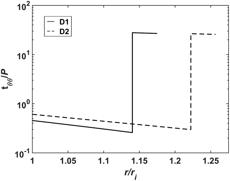
In addition to improving cell infiltration by altering the fabrication techniques, we sought potential scaffold alterations that could influence the mechanical stimuli on infiltrating cells independent of alterations to the materials or microstructure. Circumferential wall stresses in these bilayered grafts have been found to be lower than those found in the native wall,13,16 which has been shown to modulate vascular extracellular matrix synthesis and removal by vascular smooth muscle cells.34 The previous computational modeling showed that changes in graft geometry could affect the stress state in the PGS core. To demonstrate this effect, simulations using the previously described method16 were run for two scaffolds with different thicknesses for the core. With this bilayered design, consisting of a compliant PGS core surrounded by a stiffer PCL sheath, the average circumferential stress in the core is increased with a higher thickness (Fig. 8) because it bears more of the pressure load.16 This increased loading of the core could reduce the effects of stress shielding by the sheath. Therefore, two scaffolds with different thicknesses for the core were fabricated for implantation with the goal of determining if a more favorable mechanical environment in the core could lead to improved outcomes. As microstructure can strongly influence the phenotype of infiltrating cells,35 it was critical to ensure that both designs had similar fiber architectures, although different thicknesses (Fig. 3). Consistency in microstructures was achieved by holding electrospinning setup parameters constant for both designs, including the voltages of spinneret and electrode, the flow rates and concentrations of the polymers, the rotational speeds of the mandrel, and the displacements between each electrospinning component. The similar pore sizes and fiber diameters from both the cores and sheaths of each scaffold suggest that the cell-scale physical cues are similar for both designs.
FIG. 8.
Circumferential stress as a function of radial position within the scaffold wall simulated for Design 1 (solid) and Design 2 (dashed) scaffolds. Stress is normalized by the loading pressure and the radial position is normalized by the inner radius of the scaffold. Note the logarithmic scale for stress. Simulation methods have been reported previously.15 The increased thickness in Design 2 decreases stress in the sheath and increases stress in the core.
In both graft designs, surgical complications arose in the first batch of implants, leading to high perioperative mortality with 32% in D1 and 34% in D2. For those animals that survived the surgeries, high rates of thrombosis were also observed, with 25% of the surviving D1 implants and 32% of the surviving D2 implants occluding (Fig. 4A), generally within a week of implantation. Previous studies have used larger animal models, such as rats,29 or genetically modified mouse models with altered platelet activity36 that reduce the rate of occlusion compared with C57BL/6 mice. In implantations of a different scaffold design in the infrarenal aorta of wild-type mice, thrombosis did not manifest when scaffolds were seeded with bone marrow-derived mononuclear cells.4 The current protocol, with unseeded scaffolds and no anticoagulation thus provided the most stringent test of the role of geometry. Additionally, a subset of grafts ruptured at various times between 4 and 12 weeks of implantation, with 11% of D1 grafts and 12% of D2 grafts failing by rupture (Fig. 4A). Rupture generally occurred due to failure of the PCL sheath at earlier times than would be expected since PCL usually maintains mechanical integrity past 3 months of implantation.37 This finding suggests that fabrication or handling could have caused defects on the outer surface of the scaffolds (Fig. 2A, B), leading to their failure. In contrast to the implants from this study, those used previously,12 with greatly reduced pore sizes and porosities, did not exhibit either thrombosis or rupture. Increased thrombosis with the scaffolds from this study is potentially due to the effect of surface microstructure on platelet adhesion, where increasing pore size has been shown to increase platelet activation and the secretion of clotting factors.38 Furthermore, the low porosity of the previous graft generation increased the bulk stiffness of the implant and led to persistent inflammation after 1 year of implantation. Higher bulk stiffness values prevent rupture by limiting strains, and persistent inflammation indicates the long-term presence of polymer, which could continue to bear load throughout the remodeling time course. This illustrates the trade-offs in varying scaffold design to improve a single aspect of graft remodeling as the microstructural effects are coupled with multiple failure modes.
It is well known that scaffold microstructure influences the inflammatory response of infiltrating cells.35,39 In the patent samples, CD68-positive staining for macrophages was the same in both graft types (Fig. 5B), which suggests that the similar microstructures allowed accumulation of immune cells with the same temporal profiles for both designs. Yet, staining of calponin-positive smooth muscle cells differed at 24 weeks, with significantly more smooth muscle cells in the D2 grafts (Fig. 5D). No differences in smooth muscle cell content were found at earlier times, which agrees with findings that early TEVG remodeling is likely driven by immunological stimuli from the foreign body response.11 After 24 weeks, the expected differences in mechanical stimuli in the core of the graft may have driven a propensity for increased smooth muscle cell content for the D2 grafts, since the macrophage content had diminished (Fig. 5A), thus allowing mechanical stimuli to play a larger role in matrix production and organization. While both designs showed similar collagen contents at 2 and 24 weeks, D1 grafts had substantially more collagen at 12 weeks, which may have reflected the altered mechanical stimuli between the two grafts, since inflammation was similar at this time. Finally, the elastin content at 24 weeks appeared higher in D2 grafts. Functional native (elastic) arteries contain a medial layer rich in smooth muscle cells and elastin. As the D2 grafts showed both increased smooth muscle cell content and elastin content, the increased thickness of the inner PGS layer could have offered a mechanical environment more like that of the media, allowing for creation of a more native-like structure.
The mechanical data for the grafts showed that the D2 grafts were less stiff at 2 and 12 weeks, but became stiffer than the D1 grafts by 24 weeks. Because the collagen content was similar between the two designs at 24 weeks, but D2 had more smooth muscle cells and elastin, the total amount of load-bearing constituents was higher in the D2 grafts, which likely contributed to their higher stiffness. This observation indicates that although the graft composition may be similar to the native vessel, its mechanical behavior yet differs because of differences in organization of the matrix. Elastin is deposited during the perinatal period in the native arteries, and then is deformed by somatic growth.40 For these tissue-engineered arteries, the elastin is deposited in the graft wall without the prestretch that arises during maturation, which likely alters both its mechanical behavior and that of the smooth muscle cells with which it interacts.
The idea that geometry can affect long-term behavior in tissue-engineered constructs is not unique to this work.41 In this study, data suggest that differences in thickness of the bilayered construct affect the in vivo remodeling with particular implications for the emergence of a more native constituent composition. Furthermore, this work shows that electrospinning can reproducibly yield PGS vascular grafts with high, interconnected porosity and large pore sizes. There are several limitations to the current work, however, including classical concerns in vascular tissue engineering. The electrospun scaffolds in this study exhibited high rates of occlusion and rupture, both of which are unacceptable for a clinical scaffold. Absence of anticoagulant therapy or cell seeding and the use of a wild-type murine infrarenal aortic interposition model likely contributed to the higher degree of thrombosis than expected. Rupture could potentially be prevented by improved screening for defects in the sheaths (Fig. 2B) or by increasing the overall thickness of the sheath such that defects do not penetrate the full thickness. Modulating the activity of platelets or modifying the mechanical behavior of the sheath may prevent catastrophic failure, but would likely impact the deposition and remodeling of matrix. Therefore, examining alternative structures and materials that could mitigate these failure modes, while utilizing a tissue engineering approach that continues to consider the mechanobiology of the constructs, will be critical.
Disclosure Statement
No competing financial interests exist.
Funding Information
This work was supported, in part, by NIH grant R01 HL128602, as well as T32HL098039-06A1 (J.W.R.), American Heart Association Awards 18POST33990231 (J.W.R.) and 17PRE33400174 (R.K.), and National Science Foundation Award DGE1122492 (J.M.S.).
References
- 1. Yan, Y., Hong Wang, X., Yin, D., and Zhang, R.. A New Polyurethane/Heparin Vascular Graft for Small-Caliber Vein Repair. J Bioact Compat Polym 22, 323, 2007 [Google Scholar]
- 2. Braghirolli, D.I., Helfer, V.E., Chagastelles, P.C., Dalberto, T.P., Gamba, D., and Pranke, P.. Electrospun scaffolds functionalized with heparin and vascular endothelial growth factor increase the proliferation of endothelial progenitor cells. Biomed Mater 12, 025003, 2017 [DOI] [PubMed] [Google Scholar]
- 3. Shuhei, T., Hirotsugu, K., de Dios Ruiz Rosado, J., et al. Cilostazol, Not Aspirin, Prevents Stenosis of Bioresorbable Vascular Grafts in a Venous Model. Arterioscler Thromb Vasc Biol 35, 2003, 2015 [DOI] [PMC free article] [PubMed] [Google Scholar]
- 4. Udelsman, B.V., Khosravi, R., Miller, K.S., et al. Characterization of evolving biomechanical properties of tissue engineered vascular grafts in the arterial circulation. J Biomech 47, 2070, 2014 [DOI] [PMC free article] [PubMed] [Google Scholar]
- 5. Lam, C.X.F., Hutmacher, D.W., Schantz, J.-T., Woodruff, M.A., and Teoh, S.H.. Evaluation of polycaprolactone scaffold degradation for 6 months in vitro and in vivo. J Biomed Mater Res A 90A, 906, 2009 [DOI] [PubMed] [Google Scholar]
- 6. Chu, C.C. Hydrolytic degradation of polyglycolic acid: tensile strength and crystallinity study. J Appl Polym Sci 26, 1727, 1981 [Google Scholar]
- 7. Reed, A.M., and Gilding, D.K.. Biodegradable polymers for use in surgery—poly(glycolic)/poly(Iactic acid) homo and copolymers: 2. In vitro degradation. Polymer 22, 494, 1981 [Google Scholar]
- 8. Naito, Y., Lee, Y.-U., Yi, T., et al. Beyond burst pressure: initial evaluation of the natural history of the biaxial mechanical properties of tissue-engineered vascular grafts in the venous circulation using a murine model. Tissue Eng Part A 20, 346, 2013 [DOI] [PMC free article] [PubMed] [Google Scholar]
- 9. Szafron, J.M., Ramachandra, A.B., Breuer, C.K., Marsden, A.L., and Humphrey, J.D.. Optimization of tissue-engineered vascular graft design using computational modeling. Tissue Eng Part C Methods 25, 561, 2019 [DOI] [PMC free article] [PubMed] [Google Scholar]
- 10. Wissing, T.B., Haaften EE van, E.. Koch, S., et al. Hemodynamic loads distinctively impact the secretory profile of biomaterial-activated macrophages–implications for in situ vascular tissue engineering. Biomater Sci 8, 132, 2020 [DOI] [PubMed] [Google Scholar]
- 11. Szafron, J.M., Khosravi, R., Reinhardt, J., et al. Immuno-driven and mechano-mediated neotissue formation in tissue engineered vascular grafts. Ann Biomed Eng 46, 1938, 2018 [DOI] [PMC free article] [PubMed] [Google Scholar]
- 12. Khosravi, R., Best, C.A., Allen, R.A., et al. Long-Term Functional Efficacy of a Novel Electrospun Poly(Glycerol Sebacate)-Based Arterial Graft in Mice. Ann Biomed Eng 44, 2402, 2016 [DOI] [PMC free article] [PubMed] [Google Scholar]
- 13. Bellini, C., Ferruzzi, J., Roccabianca, S., Martino, E.S.D., and Humphrey, J.D.. A microstructurally motivated model of arterial wall mechanics with mechanobiological implications. Ann Biomed Eng 42, 488, 2013 [DOI] [PMC free article] [PubMed] [Google Scholar]
- 14. Tamimi, E.A., Ardila, D.C., Ensley, B.D., Kellar, R.S., and Vande Geest, J.P.. Computationally optimizing the compliance of multilayered biomimetic tissue engineered vascular grafts. J Biomech Eng 141, 0610031, 2019 [DOI] [PMC free article] [PubMed] [Google Scholar]
- 15. Emmert, M.Y., Schmitt, B.A., Loerakker, S., et al. Computational modeling guides tissue-engineered heart valve design for long-term in vivo performance in a translational sheep model. Sci Transl Med 10, eaan4587, 2018 [DOI] [PubMed] [Google Scholar]
- 16. Szafron, J.M., Breuer, C.K., Wang, Y., and Humphrey, J.D.. Stress analysis-driven design of bilayered scaffolds for tissue-engineered vascular grafts. J Biomech Eng 139, 1210081, 2017 [DOI] [PMC free article] [PubMed] [Google Scholar]
- 17. Wang, Y., Ameer, G.A., Sheppard, B.J., and Langer, R.. A tough biodegradable elastomer. Nat Biotechnol 20, 602, 2002 [DOI] [PubMed] [Google Scholar]
- 18. Eichhorn, S.J., and Sampson, W.W.. Statistical geometry of pores and statistics of porous nanofibrous assemblies. J R Soc Interface 2, 309, 2005 [DOI] [PMC free article] [PubMed] [Google Scholar]
- 19. Mirensky, T.L., Nelson, G.N., Brennan, M.P., et al. Tissue-engineered arterial grafts: long-term results after implantation in a small animal model. J Pediatr Surg 44, 1127, 2009 [DOI] [PubMed] [Google Scholar]
- 20. Lopez-Soler, R.I., Brennan, M.P., Goyal, A., et al. Development of a mouse model for evaluation of small diameter vascular grafts. J Surg Res 139, 1, 2007 [DOI] [PubMed] [Google Scholar]
- 21. Sugiura, T., Tara, S., Nakayama, H., et al. Fast degrading bioresorbable arterial vascular graft with high cellular infiltration inhibits calcification of the graft. J Vasc Surg 66, 243, 2017 [DOI] [PMC free article] [PubMed] [Google Scholar]
- 22. Ruiz-Rosado, J.D., Lee, Y.-U., Mahler, N., et al. Angiotensin II receptor I blockade prevents stenosis of tissue engineered vascular grafts. FASEB J 32, 6822, 2018 [DOI] [PMC free article] [PubMed] [Google Scholar]
- 23. Gleason, R.L., Gray, S.P., Wilson, E., and Humphrey, J.D.. A multiaxial computer-controlled organ culture and biomechanical device for mouse carotid arteries. J Biomech Eng 126, 787, 2004 [DOI] [PubMed] [Google Scholar]
- 24. Ferruzzi, J., Bersi, M.R., and Humphrey, J.D.. Biomechanical phenotyping of central arteries in health and disease: advantages of and methods for murine models. Ann Biomed Eng 41, 1311, 2013 [DOI] [PMC free article] [PubMed] [Google Scholar]
- 25. Onwuka, E., Best, C., Sawyer, A., et al. The role of myeloid cell-derived PDGF-B in neotissue formation in a tissue-engineered vascular graft. Regen Med 12, 249, 2017 [DOI] [PMC free article] [PubMed] [Google Scholar]
- 26. Bersi, M.R., Khosravi, R., Wujciak, A.J., Harrison, D.G., and Humphrey, J.D.. Differential cell-matrix mechanoadaptations and inflammation drive regional propensities to aortic fibrosis, aneurysm or dissection in hypertension. J R Soc Interface 14, 20170327, 2017 [DOI] [PMC free article] [PubMed] [Google Scholar]
- 27. Gade, P.S., Lee, K., Pfaff, B.N., Wang, Y., and Robertson, A.M.. Degradation and erosion mechanisms of bioresorbable porous acellular vascular grafts: an in vitro investigation. J R Soc Interface 14, 20170102, 2017 [DOI] [PMC free article] [PubMed] [Google Scholar]
- 28. Wu, W., Allen, R.A., and Wang, Y.. Fast-degrading elastomer enables rapid remodeling of a cell-free synthetic graft into a neoartery. Nat Med 18, 1148, 2012 [DOI] [PMC free article] [PubMed] [Google Scholar]
- 29. Lee, K.-W., Gade, P.S., Dong, L., et al. A biodegradable synthetic graft for small arteries matches the performance of autologous vein in rat carotid arteries. Biomaterials 181, 67, 2018 [DOI] [PMC free article] [PubMed] [Google Scholar]
- 30. Gaharwar, A.K., Nikkhah, M., Sant, S., and Khademhosseini, A.. Anisotropic poly (glycerol sebacate)-poly (ϵ -caprolactone) electrospun fibers promote endothelial cell guidance. Biofabrication 7, 015001, 2014 [DOI] [PMC free article] [PubMed] [Google Scholar]
- 31. Hu, J., Kai, D., Ye, H., et al. Electrospinning of poly(glycerol sebacate)-based nanofibers for nerve tissue engineering. Mater Sci Eng C 70, 1089, 2017 [DOI] [PubMed] [Google Scholar]
- 32. Jeffries, E.M., Allen, R.A., Gao, J., Pesce, M., and Wang, Y.. Highly elastic and suturable electrospun poly(glycerol sebacate) fibrous scaffolds. Acta Biomater 18, 30, 2015 [DOI] [PMC free article] [PubMed] [Google Scholar]
- 33. Balguid, A., Mol, A., van Marion, M.H., Bank, R.A., Bouten, C.V.C., and Baaijens, F.P.T.. Tailoring fiber diameter in electrospun poly(ɛ-caprolactone) scaffolds for optimal cellular infiltration in cardiovascular tissue engineering. Tissue Eng Part A 15, 437, 2008 [DOI] [PubMed] [Google Scholar]
- 34. Humphrey, J.D. Vascular adaptation and mechanical homeostasis at tissue, cellular, and sub-cellular levels. Cell Biochem Biophys 50, 53, 2007 [DOI] [PubMed] [Google Scholar]
- 35. Garg, K., Pullen, N.A., Oskeritzian, C.A., Ryan, J.J., and Bowlin, G.L.. Macrophage functional polarization (M1/M2) in response to varying fiber and pore dimensions of electrospun scaffolds. Biomaterials 34, 4439, 2013 [DOI] [PMC free article] [PubMed] [Google Scholar]
- 36. Best, C.A., Szafron, J.M., Rocco, K.A., et al. Differential outcomes of venous and arterial tissue engineered vascular grafts highlight the importance of coupling long-term implantation studies with computational modeling. Acta Biomater 94, 183, 2019 [DOI] [PMC free article] [PubMed] [Google Scholar]
- 37. Díaz, E., Sandonis, I., et al. In Vitro Degradation of Poly(caprolactone)/nHA Composites, In Vitro Degradation of Poly(caprolactone)/nHA Composites. J Nanomater J Nanomater 2014, e802435, 2014 [Google Scholar]
- 38. Milleret, V., Hefti, T., Hall, H., Vogel, V., and Eberli, D.. Influence of the fiber diameter and surface roughness of electrospun vascular grafts on blood activation. Acta Biomater 8, 4349, 2012 [DOI] [PubMed] [Google Scholar]
- 39. Sussman, E.M., Halpin, M.C., Muster, J., Moon, R.T., and Ratner, B.D.. Porous implants modulate healing and induce shifts in local macrophage polarization in the foreign body reaction. Ann Biomed Eng 42, 1508, 2014 [DOI] [PubMed] [Google Scholar]
- 40. Huang, A.H., Balestrini, J.L., Udelsman, B.V., et al. Biaxial Stretch Improves Elastic Fiber Maturation, Collagen Arrangement, and Mechanical Properties in Engineered Arteries. Tissue Eng Part C Methods 22, 524, 2016 [DOI] [PMC free article] [PubMed] [Google Scholar]
- 41. van Haaften, E.E., Wissing, T.B., Rutten, M.C.M., et al. Decoupling the Effect of Shear Stress and Stretch on Tissue Growth and Remodeling in a Vascular Graft. Tissue Eng Part C Methods 24, 418, 2018 [DOI] [PubMed] [Google Scholar]


