

Abstract
The biomechanics of human voice production are commonly studied using benchtop silicone vocal fold models that mimic the vibration of their in vivo counterparts. These models often have multiple layers of differing stiffness that represent human vocal fold tissue layers and are fabricated using a multi-step casting process. The purpose of the present study is to introduce and demonstrate a process for fabricating functional multi-layer vocal fold models using an alternative approach, termed embedded 3D printing, that is a hybrid of casting and 3D printing. In this paper the fabrication process is described. Analysis of the resulting geometric and stiffness characteristics of the layers, including layer elastic modulus values ranging from less than 1 kPa to approximately 40 kPa, is presented. The results of tests demonstrating that the models are capable of sustained phonomimetic vibration are given. Capabilities and limitations of the embedded 3D printing process are discussed. It is concluded that the process has the potential to contribute to voice biomechanics research by facilitating prospective improvements in the fabrication, design, and functionality of multi-layer vocal fold models.
Keywords: Self-oscillating VF models, embedded 3D printing, soft 3D printing, silicone VF models, voice biomechanics, vocal folds
1. Introduction
Human vocal folds (VFs) are comprised of multiple layers of different types of tissues with large variations in stiffness. Sound for voicing is produced as VFs vibrate in response to airflow from the lungs. VF vibration and resulting sound production are governed by complex interactions between tissue and airway geometry, tissue stiffness, flow dynamics, acoustics, and other features and phenomena.
One of the main goals of voice research is to improve the clinical care of individuals with voice disorders. One common approach is to use benchtop silicone, self-oscillating, phonomimetic VF models in laboratory experiments (Kniesburges et al., 2011). Compared with other methods, such as in vivo experiments and excised larynx studies, synthetic VF model experiments allow convenient instrument access, enable data acquisition for extended periods of time, and facilitate parametric studies involving manipulation of variables that would be difficult or impossible to control in vivo or using excised larynges.
Silicone VF models have been shown to reasonably replicate the structure and resulting vibratory characteristics of human VFs. These models have ranged from single-layer models that approximate the overall effective stiffness of the human VFs (e.g., Thomson et al., 2005; Zhang et al., 2009; Kniesburges et al., 2017), to multi-layer models with distinct layers of differing stiffness that represent the human VF layered structure (e.g., Drechsel et al., 2008; Murray and Thomson, 2011, 2012; Zhang and Luu, 2012;). The multi-layer models have been shown to exhibit more life-like responses than single-layer models. For example, the so-called “EPI” multi-layer VF model (Murray and Thomson, 2011, 2012) exhibited vibration frequency and onset pressure within the corresponding ranges of human phonation. Models such as these have been used, for example, to study aspects of voice production such as glottal airflow and flow-structure interactions (e.g., Neubauer et al., 2007; Becker et al., 2009; Kniesburges et al., 2013; Lodermeyer et al., 2015), phonatory aeroacoustics and flow-structure-acoustic interactions (e.g., Zhang et al., 2006a,b; Lodermeyer et al., 2018; McPhail et al., 2019; Migimatsu and Tokuda, 2019), and vocal fold asymmetry (e.g., Zhang, 2010; Zhang and Luu, 2012; Zhang et al., 2013; Tokuda and Shimamura, 2017; Bouvet et al., 2020).
Improvements to VF models to more closely replicate human VF morphology and function is an active area of voice biomechanics research. Despite the advantages of multi-layer VF models, their use is challenged by difficulties with the current multi-step casting process in which each layer is cast around previous layers using a coordinated set of negative molds. This process can be inefficient and time-consuming, especially when multiple unique geometries are desired. Furthermore, because some layers are comprised of exceptionally soft silicone materials (elastic modulus often less than 1 kPa), fabrication yield can be low.
Because of these challenges, fabricating VF models via 3D printing has been pursued. In previous work (Romero et al., in press), single-layer VF models were fabricated by extruding silicone into a previously-developed micro-organogel (O’Bryan et al., 2017). The 3D-printed VF models exhibited desirable vibration characteristics, but residual micro-organogel within the finished prints was undesirable. Extension of this printing process to fabricate multi-layer VF models has not yet been demonstrated.
The purpose of this paper is to demonstrate that phonomimetic multi-layer VF models can be fabricated via an alternative 3D printing process termed “embedded 3D printing,” a process that is a hybrid of casting and 3D printing (Wu et al., 2011; Muth et al., 2014; Truby and Lewis, 2016; Wehner et al., 2016; Helmer et al., 2017; Zehnder et al., 2017; Truby et al., 2018). In embedded 3D printing, a reservoir of the desired shape is filled with a curable gel-like material (“support matrix”). Shapes, channels, and inclusions of different materials are then “embedded” within the support matrix by extruding curable or non-curable inks into the matrix through a long thin needle. After printing, the support matrix (and in some cases the curable inks) are solidified to form a single multi-material part, with the outer geometry being the same as the reservoir cavity and the inner geometries being formed by the deposited ink.
In this paper an embedded 3D printing approach for fabricating VF models with multiple layers of soft, elastic silicones is described in which the inner VF layers are printed within a VF-shaped reservoir. In the following sections, the process is summarized. Descriptions of the layer geometric and stiffness characteristics are presented. Vibration test results that demonstrate that the models possess the required properties for self-oscillation and are sufficiently durable to withstand phonomimetic vibration are shown. Finally, capabilities and limitations of the process are discussed and the outlook for future applications is summarized.
2. Methods
2.1. Model Overview
The multi-layer VF model used in this study was based on the EPI model of Murray and Thomson (2011, 2012) which consists of four layers representing the VF tissue structure (body, ligament, superficial lamina propria, and epithelium; see Fig. 1) and a fiber within the ligament layer to simulate anisotropy and restrict inferior-superior motion during vibration. The model in Murray and Thomson (2011, 2012) was cast from addition-cure silicone elastomers Ecoflex 00–30 and Dragon Skin 10 FAST mixed with various ratios of Silicone Thinner (all products from Smooth-On, Inc.) to achieve the desired stiffness of each layer. In the present study, the model was fabricated by embedded 3D printing the ligament and body layers within a VF-shaped reservoir filled with material representing the superficial lamina propria (SLP). A fiber and an epithelial layer were also added. The geometry followed that of the previous cast model, except for a slight modification to the interface between the body and ligament layers to enable printing (see Fig. 2). The 3D-printed model materials were different than for the cast model, but were chosen such that their stiffnesses were similar to the corresponding layers in the cast model.
Fig. 1.

EPI VF model with four material layers (epithelium, superficial lamina propria [SLP], ligament, and body). The backing is used to facilitate demolding. The fiber location, fiber geometry, and epithelium thickness are approximate. Anatomical directions are also indicated (A: anterior, P: posterior, I: inferior, S: superior, M: medial, L: lateral). Anterior-posterior length is approximately 17 mm. Scale bar length is approximately 10 mm.
Fig. 2.
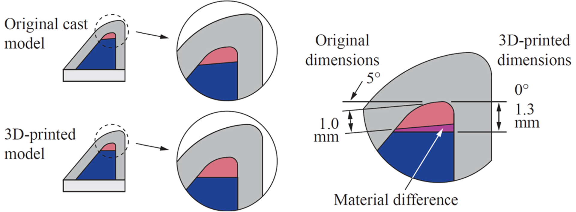
Illustration comparing the difference between the geometries of the previous cast EPI VF model and the present 3D-printed model. For embedded 3D printing, the interface of the ligament and body layers was modified to be horizontal and better match the height of an integer number of printed layers. The epithelium is not shown.
2.2. Silicone Preparation
The materials used to fabricate the 3D-printed model are listed in Table 1. The SLP, ligament, and body layer materials were prepared by first mixing part B of the silicone with Silicone Thinner (this and all other materials listed are manufactured by Smooth-On, Inc., unless otherwise noted), pigment (Silc-Pig), cure decelerator (Slo-Jo), and fumed silica (Ure-Fil 9). These components were mixed at 3500 rpm for 60 s using a planetary centrifugal mixer (DAC 150.1 FVZ-K SpeedMixer, FlackTek) and then degassed for 120 s. Part A of the silicone was added, and all components were mixed at 3500 rpm for 60 s and then degassed for 120 s. The ligament and body layer materials (i.e., the inks) were poured into 3 ml syringes (CareTouch) affixed with blunt-tip dispensing needles for printing. The epithelium and backing layer materials were each prepared by mixing at 3500 rpm for 60 s and degassing under vacuum for approximately 120 s.
Table 1:
Components used to create the layers of the 3D-printed EPI VF model. EF-35: Ecoflex 00–35 FAST, DS-10: Dragon Skin 10 FAST.
| Layer | Silicone | Mixing Ratio (A:B:Thinner, by weight) | Pigment | Cure decelerator (wt% of part B) | Fumed silica (wt% of total) |
|---|---|---|---|---|---|
| SLP | EF-35 | 1:1:8 | - | 4% | 1.5% |
| Ligament | EF-35 | 1:1:3.6 | red | 4% | - |
| Body | EF-35 | 1:1:0.35 | blue | 6% | - |
| Epithelium | DS-10 | 1:1:1 | white | - | - |
| Backing* | DS-10 | 1:1:1 | white | - | - |
The backing was an extra layer to facilitate demolding.
2.3. Reservoir Fabrication
The reservoir was a mold with a profile that followed the shape of the SLP layer (Figs. 3 and 4), fabricated as follows. A positive of the SLP geometry was first fabricated (Fig. 4 step 1). The material for the reservoir was prepared by mixing parts A and B of the silicone Smooth-Sil 936 at a 10:1 (A:B) ratio by weight. The components were mixed at 2200 rpm for 120 s, degassed for approximately 5 min, poured over the positive, and cured. The positive was demolded from the cured reservoir, and the reservoir was then cut for fiber placement as shown in Fig. 3 and Fig. 4 step 2.
Fig. 3.

Reservoir for fabrication of the 3D-printed EPI VF model. The reservoir’s cavity geometry is the same as the negative mold for the SLP layer used to create the previous cast EPI VF model (see Fig. 4 step 1). On the right, a section view of the reservoir shows the inner profile of the reservoir and how the SLP, ligament, and body layers were oriented within the reservoir during printing.
Fig. 4.

Steps for fabricating the VF model via embedded 3D printing. (1) Create positive mold of SLP layer. (2) Create reservoir with cut for fiber insertion. (3) Coat reservoir with release agent. (4) Fill reservoir with SLP support matrix silicone. (5a,b) Print ligament layer within reservoir, beginning near reservoir bottom, and then insert fiber. (6a,b) Print body layer beginning at interface of ligament layer. (7–8) Remove overflow material and then cure in microwave. (9) Pour backing into remaining cavity and let model cure and cool completely. (10) Remove VF model from reservoir. (11) Trim excess backing material and gently clean model with acetone. (12) Attached model to mounting plate. (13) Pour epithelial layer and cure.
2.4. Model Fabrication
The embedded 3D printing process used to fabricate the multi-layer VF models was based on the work of Muth et al. (2014) and Wehner et al. (2016). The printer was a modified 12×12 F8 Zen Toolworks CNC milling machine with a custom dual-headed extruder (Fig. 5), similar to the setup described in Romero (2019) and Greenwood (2020). Relevant print settings are summarized in Table 2 with more details described in Supplementary File 1. The reservoir was coated with mold release agent (Pol-Ease 2300, Polytek), brushed, then placed under vacuum for approximately 120 s (Fig. 4 step 3). The support matrix silicone representing the SLP layer (Table 1 row 1) was carefully poured into the VF portion of the reservoir cavity to avoid bubble formation (step 4). The reservoir containing the uncured SLP silicone was then fixed to the print bed.
Fig. 5.
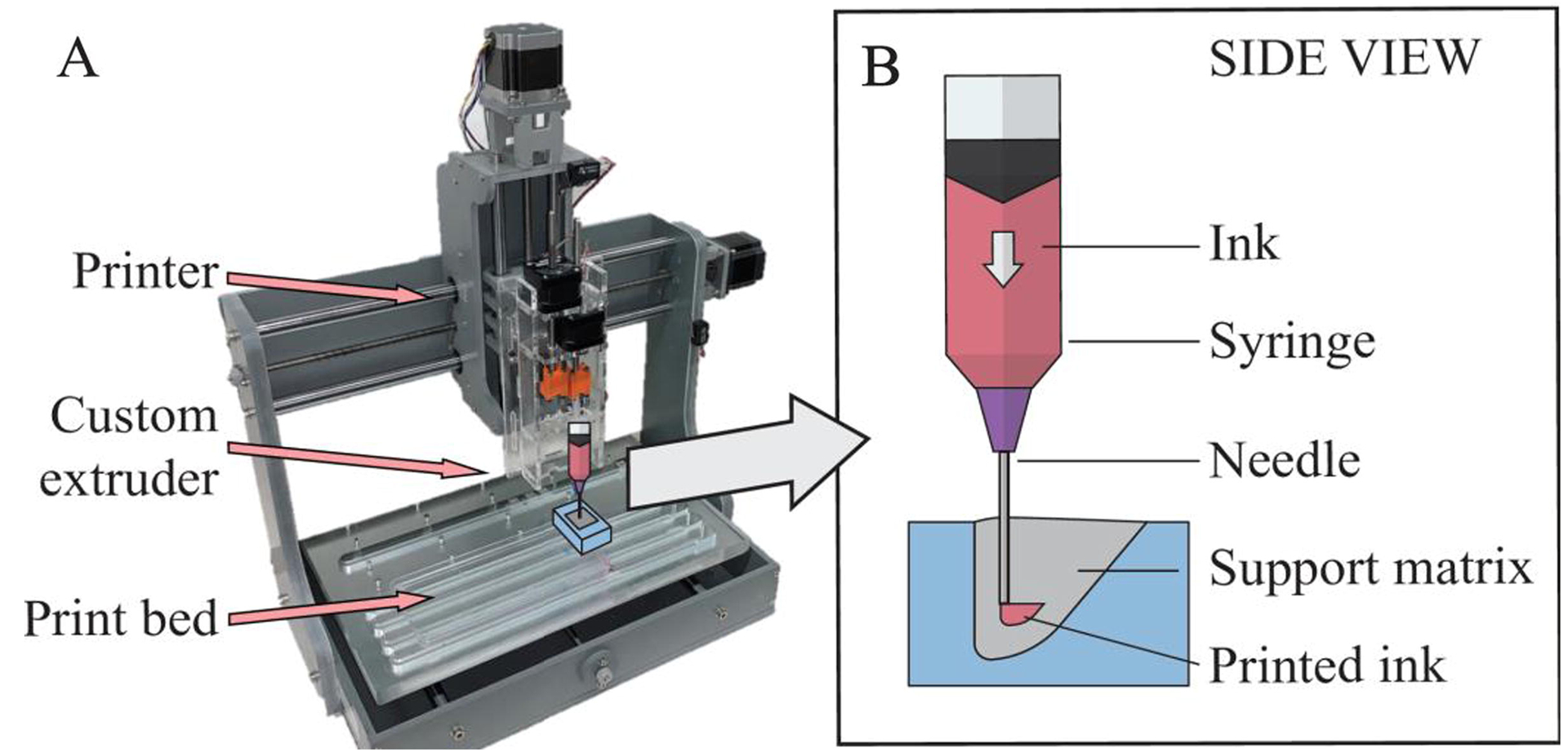
(A) Printer setup for fabricating embedded 3D-printed VF models. (B) Side-view illustration of printing the ligament layer within the reservoir (to facilitate visualization, illustrations not drawn to scale).
Table 2:
Summary of print settings.
| Print Setting | Value |
|---|---|
| Layer height and nozzle diameter | 30-gauge needle: 0.159 mm 25-gauge needle: 0.26 mm |
| Filament diameter | 8.66 mm (syringe ID) |
| Infill percentage, pattern, angle | 60%, rectilinear, 45° |
| Perimeters, supports | None, none |
| Print and travel speed | 28.8 mm/s |
| Slicing software | Ultimaker Cura 4.3.0 |
The ligament layer was first printed within the filled reservoir (Fig. 4 step 5; see also Supplementary Video 1) using a 0.5 in long, 30-gauge needle (Jensen Global). The fiber was then manually inserted into the ligament layer using the cuts in the reservoir as guides (between steps 5–6). The body layer was then printed using a 0.5 in long, 25-gauge needle (step 6). Print time for one model was less than six min.
After printing, any material overflow due to the printed ink displacing support matrix was removed using a flat edge (Fig. 4 steps 7–8) and the model was cured by microwaving the silicone-filled reservoir for three min (700W microwave; see Supplementary File 1). Soon afterwards the backing was created by pouring the backing silicone into the remaining portion of the warm reservoir (step 9). After cooling to room temperature (approximately 30 min), the model was removed from the reservoir (step 10) and the backing layer was trimmed (step 11). The exterior of the model was then gently rinsed with acetone to wash away release agent and allowed to air dry.
The model was attached to a plate using silicone adhesive (SilPoxy; Fig. 4 step 12; see also Fig. 6). The epithelial layer was created by pouring silicone over the model in a manner similar to that which has been described previously (Murray and Thomson, 2012) and allowing to cure for approximately 1 hour at room temperature (step 13). Excess epithelial material around the model was trimmed as needed, and the model was coated with talcum powder to reduce surface tackiness.
Fig. 6.

Images of embedded 3D-printed VF model after mounting in plate, before (A) and after (B,C) pouring the epithelium (both before applying talcum powder). Images are of isometric (A), front-right (B), and front (C) views with anatomical directions indicated. In (A), the large arrow indicates direction of flow during vibration testing. In (C), flow is into the page. For reference, the anterior-posterior dimension of the models (i.e., the width in C) was approximately 17 mm. Shown is model “B” (see Fig. 7).
2.5. Geometry and Stiffness Tests
Exterior images of the printed models were acquired before mounting and pouring the epithelium. Additionally, each layer’s stiffness was tested using the same mixtures prepared during model fabrication. The stiffnesses of the ligament, body, and epithelial layers were measured using printed (ligament, body; qty. 1 each) and cast (SLP, epithelium; 3 each) rectangular dogbone specimens and a uniaxial tensile tester generally following the process described by Romero (2019). Tensile testing was performed within one hour of the first set of vibration tests. Because the ligament and body layers were created via embedded 3D printing, the specimens for these two layers were created by printing each ink into a dogbone-shaped reservoir filled with SLP support matrix. Due to the short working life of the silicones (approx. 120 min), just one specimen each was printed for the ligament and body layers.
2.6. Vibration Tests
Similar to previous studies (e.g., Murray and Thomson, 2012, Fig. 6 therein), flow-induced vibration tests were conducted using model pairs in full-larynx configurations. Tension was applied to the fibers similar to that described in Murray and Thomson (2011, 2012). Onset pressure (the pressure required to initiate flow-induced vibration) was measured using a pressure transducer (26PC 6CF6G, Honeywell) mounted approximately 2 cm upstream of the model. Model vibration was imaged using a high-speed camera (SC2+, Edgertronic, 5912.4 fps) mounted superior to the model using LED lights for illumination (Model 900420H, Visual Instrumentation Corp.) The images were used to create a digital kymogram and calculate vibration frequency.
3. Results & Discussion
3.1. Layer Geometry
As shown in Fig. 7, the layers within the printed VF model are clearly identifiable and follow the desired geometries. (Two models are shown here; eight models fabricated from the same material mixtures are shown in Supplementary File 1.) The embedded 3D printing process generated ligament and body layers in the correct locations, although a few geometric aspects could be improved, such as ligament and body layer alignment, ligament and body layer geometric fidelity, and fiber position. Factors that contributed to these geometric characteristics include manual alignment of the needle prior to printing each layer, flow rate of extruded material during printing, removal of material overflow after printing, and variability in the fiber slot depth in the reservoirs and in manually inserting the fibers. Because the purpose of this study was to determine the feasibility of utilizing embedded 3D printing to fabricate functional VF models, limited refinement of fabrication steps, including these specific factors, was performed and it is anticipated that further work will improve geometric fidelity.
Fig. 7.

Orthogonal and perspective views of two 3D-printed VF models before pouring epithelial layer and before applying talcum powder. Black dotted lines overlaid in the “Left” and “Right” views provide approximate comparison of desired and actual geometry. White dashed lines in the “Back” view overlay the fiber. For reference, the anterior-posterior dimension of the models (i.e., the width in the front and back views) was approximately 17 mm. See Supplementary File 1 for images and discussion of additional models. *Images in “Angle” and “Top” views have been scaled to be approximately uniform across models.
3.2. Material Stiffness
The stiffness of each layer is listed in Table 3 along with the values reported by Murray and Thomson (2011). The printed layer modulus values were 12.87 kPa (body) and 2.25 kPa (ligament). The elastic modulus was calculated as the slope at 10% strain of a second-order polynomial fit to the stress-strain data from 0 to 20% strain (see Supplementary File 1). As seen in Table 3, the body, ligament, and SLP modulus values are somewhat higher, but in the same general range as the values reported by Murray and Thomson (2011). The lower epithelium stiffness in this study is attributed to differences in experimental setup and modulus calculations, as well as inherent variability in silicone stiffness due to factors such as processing environment, material age, and time between initial curing and material testing. Notwithstanding these differences, as shown in Sec. 3.3 the printed model self-oscillated as desired. In the future, modulus values can be tuned by adjusting Thinner concentration.
Table 3:
Comparison of layer material stiffness for the previous cast and current embedded 3D-printed EPI VF models.
| Previous cast EPI VF modela | Current embedded 3D-printed EPI VF model | |||||
|---|---|---|---|---|---|---|
| Model layer | Material | Mixing ratio | Tensile modulus (kPa) | Material | Mixing ratiob | Tensile modulus (kPa)c |
| SLP | EF-30 | 1:1:8 | 0.2 | EF-35 | 1:1:8 | 0.91d |
| Ligament | EF-30 | 1:1:4 | 1.6 | EF-35 | 1:1:3.6 | 2.25 |
| Body | EF-30 | 1:1:1 | 11.8 | EF-35 | 1:1:0.35 | 12.87 |
| Epithelium | DS-10 | 1:1:1 | 49.8 | DS-10 | 1:1:1 | 39.74d |
Values from (Murray and Thomson, 2011).
Details of each material layer are included in Table 1.
Modulus calculated as the slope at 10% strain of a second-order polynomial fit to engineering stress vs. strain data from 0 to 20% strain.
Three samples of these two layers were tested, with standard deviations of 0.12 kPa (SLP) and 1.19 kPa (epithelium).
These material data demonstrate two important capabilities of the present embedded 3D printing process: first, multi-layer parts with ultra-soft regions can be fabricated, and second, composite parts with large variations in stiffness can be produced. The matrix (reservoir) material in this study was generally much less stiff than what has been used in previous embedded 3D printing studies. For example, Muth et al. (2014), Wehner et al. (2016), Zehnder et al. (2017), and Truby et al. (2018) used Ecoflex 00–30 (EF-30) without Thinner (i.e., a mixing ratio of 1:1:0 of A:B:Thinner). Muth et al. also used EF-30 1:1:0.1, and Truby et al. also used Sorta-Clear 40 and Ecoflex 00–10 in their prints. The elastic modulus of EF-30 1:1:0 is approximately 69 kPa (based on a reported 100% modulus value of 69 kPa [Smooth-On, 2018] and assuming a linear stress-strain response), whereas the cured stiffness of the reservoir matrix in this study (i.e., the SLP layer, formed using 1:1:8 Ecoflex 00–35) was 0.91 kPa, which leads to a rough estimate of the current matrix stiffness being 1.3% of the stiffness of the matrix in these previous studies.
3.3. Vibration Test Results
Eight embedded 3D-printed VF models (i.e., four pairs) were tested. Models AB, CD, and EF were tested the same day as fabrication; model GH was tested the following day. These models exhibited flow-induced vibration with several favorable characteristics similar to those of human phonation and the previous cast models described by Murray and Thomson (2011, 2012), albeit with some differences. The onset pressures of printed models AB, CD, EF, and GH were 0.87, 0.82, 0.85, and 1.24 kPa, respectively. The close grouping of the onset pressures of the first three models and the higher onset pressure of model GH suggests that some additional material curing had transpired in the time period following fabrication. This post-cure response is expected to be common to both casting and 3D printing processes, an understanding of the precise nature of which could benefit from further exploration. By way of comparison, onset pressures have ranged from 0.27 to 0.43 kPa for EPI cast models (Murray and Thomson, 2011, 2012) and from 0.84 to 1.68 kPa for three other types of cast models studied by Murray and Thomson (2012). In human phonation, Baken and Orlikoff (2000) report that onset pressures in the general range of 0.29 to 0.49 kPa are typical and cite studies in which subglottal pressures in excess of 2 kPa at loud intensities have been reported.
The vibration frequencies of the printed models at a range of pressures are shown in Fig. 8. Frequencies of model pairs AB, CD, and EF (tested the same day as fabrication) ranged from 125 to 180 Hz. Frequencies of model pair GH (tested the following day) ranged from 172 to 216 Hz. All models exhibited increases in frequency with pressure. Variability in model frequencies was not unexpected due to variations in layer geometry and fiber position (as documented in Supplementary File 1). Frequencies of the cast EPI models of Murray and Thomson (2011, 2012) were between approximately 100 Hz and 115 Hz. Citing numerous studies, Baken and Orlikoff (2000) report mean fundamental frequencies of spontaneous speech ranging from approximately 100 to 136 Hz for adult males and 189 to 224 Hz for adult females.
Fig. 8.

Frequency (top) and maximum glottal width (bottom) for four model pairs at four different pressures.
Maximum glottal width measurements from the high-speed images are also shown in Fig. 8, with values ranging from 0.91 to 3.2 mm. The maximum glottal width of the cast EPI model in Murray and Thomson (2012) was approximately 1.5 mm at a subglottal pressure of 20% above onset pressure. In human phonation, maximum glottal width is variable and depends on many factors, but values on the order of 2 mm for adult males during sustained vowel production have been reported (Schuberth et al., 2002).
High-speed images and corresponding kymograms are shown in Fig. 9; high-speed videos are included as Supplementary Videos 2 through 5. These suggest the presence of an alternating convergent-divergent profile that was also seen in the previous cast EPI model and that is a hallmark characteristic of human VF vibration.
Fig. 9.

3D-printed EPI VF model pair AB during vibration testing over one vibration cycle at two pressures. (Left): Superior-view high-speed images at subglottal pressures of 0.89 kPa (a-i) and 2.60 kPa (j-r). Times between successive images shown here vary, so numbers have been included to denote fraction of one cycle. (Right): Kymograms at 0.89 kPa (top) and 2.60 kPa (bottom).
To summarize the vibration test results, the pressures required to initiate vibration of the 3D printed models are well within the capability of the human lungs for speech and singing. The model frequencies are also within the range of the human voice, and the glottal widths are comparable to that which is typical in human voicing. Differences between 3D printed models and the previous cast models are attributed to differences in stiffness and to other geometric variations; future tuning of layer stiffness and geometry could be pursued.
4. Conclusions
A method of fabricating multi-layer VF models via embedded 3D printing, a hybrid of casting and 3D printing, has been introduced and demonstrated. The geometry, stiffness, and vibration characteristics of the 3D-printed VF model were similar to those of the previous cast model. The printed model geometry was found to be acceptable, though process refinement would likely improve geometric fidelity and spatial resolution. The stiffnesses of the ligament, body, and SLP layers within the 3D-printed model were higher than the cast model. It is expected that a lower stiffness could be achieved by adjusting Thinner concentration. The 3D-printed model withstood vibration, demonstrating the feasibility of fabricating functional multi-layer VF models via embedded 3D printing. Quantitative vibration characteristics differed somewhat from the cast model and human phonation, but were suitably comparable to each. These differences were attributed to the relatively higher stiffnesses of most layers in the current model as well as geometric variations, and could likely be reduced by tuning the layer stiffness values and refining the printing and fabrication process.
The printing process described herein differs from that described by Romero et al. (in press) and others who developed similar processes (Bhattacharjee et al., 2015; Fripp et al., 2016; Hinton et al., 2016; Hajash et al., 2017; O’Bryan et al., 2017; Abdollahi et al., 2018; Greenwood et al., 2021) in that the support matrix in the present work is an inherently curable material and the inks and support matrix are cured together. In contrast, the support matrices used by Romero et al. (in press) and in similar studies remained uncured, and the support matrix used in Greenwood et al. (2021) only cured within the deposited ink structure. Further, the work described herein differs somewhat from other reports of embedded 3D printing processes in that the materials of the present study were significantly softer and the inks were embedded to form bulk composite geometries instead of small features such as channels or inclusions (Muth et al., 2014; Wehner et al., 2016; Zehnder et al., 2017; Truby et al., 2018; brief descriptions of these studies included in Supplementary File 1). The present work resulted in solid-infill composite geometries printed within an ultra-low stiffness silicone support matrix. The stiffness ratio of inks and support matrix was a factor of approximately 5.8 for the ligament ink and 56 for the body ink (see Supplementary File 1), and it is expected that this range could be expanded by using different materials and mixing ratios.
The approach described herein may facilitate incorporation of VF model features and possess advantages beyond that which can be accomplished via traditional casting processes. For example, complex internal layers could conceivably be printed that could not be cast, and other features could be embedded within the models (e.g., resistive strain sensors using conductive silicone ink). Moreover, models with geometrically-different internal layers could be printed without the time investment required to create new molds. Finally, additional features could be incorporated within the models, such directional fibers, which may be useful in future studies of voice biomechanics.
Several limitations are acknowledged. Because the fabrication process is a hybrid of casting and 3D printing, casting-related errors (e.g., failure during demolding) exist as with current VF model casting practices. Similarly, the outer geometry of the printed model is limited to a castable shape that is accessible by a printing needle. Inner layer geometries are limited by printer spatial resolution, which may be inferior to casting. Printing also introduces fabrication complexities associated with 3D printer hardware and parameter settings.
Suggestions for future work include improving layer spatial resolution, such as by decreasing needle size and improving printer hardware, and developing processes for printing layers with continuous material gradients. Further exploration and refinement of extrusion flow rate characteristics would be beneficial. To the authors’ knowledge, Ecoflex 00–35 has not previously been used in VF modeling studies, but experience using this material for the present research has led to optimism that it may possess fabrication-related advantages over previously-used Ecoflex 00–30. Further exploration of candidate materials, including more in-depth study of Ecoflex 00–35 properties, is thus recommended.
Ultimately, it is anticipated that this process, along with possible future advances such as those mentioned above, will open new doors for facilitating novel improvements in the fabrication, design, and functionality of multi-layer VF models.
Supplementary Material
Acknowledgements
This work was supported by grant number R01 DC005788 from the National Institute on Deafness and Other Communication Disorders. Its content is solely the responsibility of the authors and does not necessarily represent the official views of the NIDCD or the National Institutes of Health. The authors gratefully acknowledge Serah Hatch for aiding in testing and in the design of several fabrication steps and the VF model reservoir, Austin Vaterlaus for helpful discussions and initial testing, and Dr. Mark B. Colton for helpful discussions and advisement.
Footnotes
Publisher's Disclaimer: This is a PDF file of an unedited manuscript that has been accepted for publication. As a service to our customers we are providing this early version of the manuscript. The manuscript will undergo copyediting, typesetting, and review of the resulting proof before it is published in its final form. Please note that during the production process errors may be discovered which could affect the content, and all legal disclaimers that apply to the journal pertain.
Declaration of Competing Interest
Brigham Young University has filed a PCT application, with the authors included among the co-inventors, on 3D printing materials within a support matrix composed of curable materials.
References
- Abdollahi S, Davis A, Miller JH, Feinberg AW, 2018. Expert-guided optimization for 3D printing of soft and liquid materials. PLoS One 13, e0194890. [DOI] [PMC free article] [PubMed] [Google Scholar]
- Baken RJ, Orlikoff RF 2000. Clinical Measurement of Speech and Voice, 2nd ed. (Singular, San Diego: ). [Google Scholar]
- Becker S, Kniesburges S, Müller S, Delgado A, Link G, Kaltenbacher M, Döllinger M, 2009. Flow-structure-acoustic interaction in a human voice model. J. Acoust. Soc. Am 125, 1351–1361. [DOI] [PubMed] [Google Scholar]
- Bhattacharjee T, Zehnder SM, Rowe KG, Jain S, Nixon RM, Sawyer WG, Angelini TE, 2015. Writing in the granular gel medium. Sci. Adv 1, e1500655. [DOI] [PMC free article] [PubMed] [Google Scholar]
- Bouvet A, Tokuda I, Pelorson X, Van Hirtum A, 2020. Influence of level difference due to vocal folds angular asymmetry on auto-oscillating replicas. J. Acoust. Soc. Am 147, 1136–1145. [DOI] [PubMed] [Google Scholar]
- Drechsel JS, Thomson SL, 2008. Influence of supraglottal structures on the glottal jet exiting a two-layer synthetic, self-oscillating vocal fold model. J. Acoust. Soc. Am 123, 4434–4445. [DOI] [PMC free article] [PubMed] [Google Scholar]
- Fripp T, Frewer N, Green L, 2016. Method and apparatus for additive manufacturing. US Patent number US20160263827A1.
- Greenwood TE, Hatch SE, Colton MB, Thomson SL, 2021. 3D Printing Ultra-Low Stiffness Silicone Within a Locally-Curable Support Matrix. Addit. Manuf, 37, 101681. [DOI] [PMC free article] [PubMed] [Google Scholar]
- Greenwood TE, 2020. Silicone 3D printing processes for fabricating synthetic, self-oscillating vocal fold models. MS thesis, Brigham Young University. [Google Scholar]
- Hajash K, Sparrman B, Guberan C, Laucks J, Tibbits S, 2017. Large-scale rapid liquid printing. 3D Print. Addit. Manuf 4, 122–131. [Google Scholar]
- Helmer D, Voigt A, Wagner S, Keller N, Sachsenheimer K, Kotz F, Nargang TM, Rapp BE, 2017. Suspended Liquid Subtractive Lithography: One-step generation of 3D channel geometries in viscous curable polymer matrices. Sci. Rep 7, 3–8. [DOI] [PMC free article] [PubMed] [Google Scholar]
- Hinton TJ, Hudson A, Pusch K, Lee A, Feinberg AW, 2016. 3D printing PDMS elastomer in a hydrophilic support bath via freeform reversible embedding. ACS Biomater. Sci. Eng 2, 1781–1786. [DOI] [PMC free article] [PubMed] [Google Scholar]
- Kniesburges S, Thomson SL, Barney A, Triep M, Sidlof P, Horacek J, Brücker C, Becker S, 2011. In vitro experimental investigation of voice production. Curr. Bioinform 6, 305–322. [DOI] [PMC free article] [PubMed] [Google Scholar]
- Kniesburges S, Hesselmann C, Becker S, Schlücker E, Döllinger M, 2013. Influence of vortical flow structures on the glottal jet location in the supraglottal region. J. Voice 27, 531–544. [DOI] [PubMed] [Google Scholar]
- Kniesburges S, Birk V, Lodermeyer A, Schützenberger A, Bohr C, Becker S, 2017. Effect of the ventricular folds in a synthetic larynx model. J. Biomech 55, 128–133. [DOI] [PubMed] [Google Scholar]
- Lodermeyer A, Becker S, Döllinger M, Kniesburges S, 2015. Phase-locked flow field analysis in a synthetic human larynx model. Exp. Fluids 56, 77. [Google Scholar]
- Lodermeyer A, Tautz M, Becker S, Döllinger M, Birk V, Kniesburges S, 2018. Aeroacoustic analysis of the human phonation process based on a hybrid acoustic PIV approach. Exp. Fluids 59, 13. [Google Scholar]
- McPhail MJ, Campo ET, Krane MH, 2019. Aeroacoustic source characterization in a physical model of phonation. J. Acoust. Soc. Am 146, 1230–1238. [DOI] [PMC free article] [PubMed] [Google Scholar]
- Migimatsu K, Tokuda IT, 2019. Experimental study on nonlinear source-filter interaction using synthetic vocal fold models. J. Acoust. Soc. Am 146, 983–997. [DOI] [PubMed] [Google Scholar]
- Murray PR, Thomson SL, 2011. Synthetic, multi-layer, self-oscillating vocal fold model fabrication. JOVE-J. Vis. Exp 58, e3498. [DOI] [PMC free article] [PubMed] [Google Scholar]
- Murray PR, Thomson SL, 2012. Vibratory responses of synthetic, self-oscillating vocal fold models. J. Acoust. Soc. Am 132, 3428–3438. [DOI] [PMC free article] [PubMed] [Google Scholar]
- Muth JT, Vogt DM, Truby RL, Mengüç Y, Kolesky DB, Wood RJ, Lewis JA, 2014. Embedded 3D printing of strain sensors within highly stretchable elastomers. Adv. Mater 26, 6307–6312. [DOI] [PubMed] [Google Scholar]
- Neubauer J, Zhang Z, Miraghaie R, Berry DA, 2007. Coherent structures of the near field flow in a self-oscillating physical model of the vocal folds. J. Acoust. Soc. Am 121, 1102–1118. [DOI] [PubMed] [Google Scholar]
- O’Bryan CS, Bhattacharjee T, Hart S, Kabb CP, Schulze KD, Chilakala I, Sumerlin BS, Sawyer WG, Angelini TE, 2017. Self-assembled micro-organogels for 3D printing silicone structures. Sci. Adv 3, e1602800. [DOI] [PMC free article] [PubMed] [Google Scholar]
- Romero RGT, 2019. The development of 3D-printed synthetic vocal fold models. MS thesis, Brigham Young University. [Google Scholar]
- Romero RG, Colton MB, Thomson SL 3D-Printed synthetic vocal fold models. J. Voice, in press. [DOI] [PMC free article] [PubMed] [Google Scholar]
- Schuberth S, Hoppe U, Döllinger M, Lohscheller J, Eysholdt U 2002. High-precision measurement of the vocal fold length and vibratory amplitudes. Laryngoscope 112:1043–1049. [DOI] [PubMed] [Google Scholar]
- Smooth-On, 2018. Ecoflex™ series product sheet. https://www.smooth-on.com/tb/files/ECOFLEX_SERIES_TB.pdf, accessed 17 Aug 2020.
- Syndergaard KL, Dushku S, Thomson SL, 2017. Electrically conductive synthetic vocal fold replicas for voice production research. J. Acoust. Soc. Am 142, EL63–EL68. [DOI] [PMC free article] [PubMed] [Google Scholar]
- Thomson SL, Mongeau L, Frankel SH, 2005. Aerodynamic transfer of energy to the vocal folds. J. Acoust. Soc. Am 118, 1689–1700. [DOI] [PubMed] [Google Scholar]
- Tokuda IT, Shimamura R, 2017. Effect of level difference between left and right vocal folds on phonation: Physical experiment and theoretical study. J. Acoust. Soc. Am 142, 482–492. [DOI] [PubMed] [Google Scholar]
- Truby RL, Lewis JA, 2016. Printing soft matter in three dimensions. Nature 540, 371–378. [DOI] [PubMed] [Google Scholar]
- Truby RL, Wehner M, Grosskopf AK, Vogt DM, Uzel SGM, Wood RJ, Lewis JA, 2018. Soft somatosensitive actuators via embedded 3D printing. Adv. Mater 30, 1706383. [DOI] [PubMed] [Google Scholar]
- Wehner M, Truby RL, Fitzgerald DJ, Mosadegh B, Whitesides GM, Lewis JA, Wood RJ, 2016. An integrated design and fabrication strategy for entirely soft, autonomous robots. Nature 536, 451–455. [DOI] [PubMed] [Google Scholar]
- Wu W, DeConinck A, Lewis JA, 2011. Omnidirectional printing of 3D microvascular networks. Adv. Mater 23, H178–H183. [DOI] [PubMed] [Google Scholar]
- Zehnder J, Knoop E, Bächer M, Thomaszewski B, 2017. MetaSilicone: Design and fabrication of composite silicone with desired mechanical properties. ACM Trans. Graph 36, 1–13. [Google Scholar]
- Zhang Z, 2010. Vibration in a self-oscillating vocal fold model with left-right asymmetry in body-layer stiffness. J. Acoust. Soc. Am 128, EL279–EL285. [DOI] [PMC free article] [PubMed] [Google Scholar]
- Zhang Z, Hieu Luu T, 2012. Asymmetric vibration in a two-layer vocal fold model with left-right stiffness asymmetry: Experiment and simulation. J. Acoust. Soc. Am 132, 1626–1635. [DOI] [PMC free article] [PubMed] [Google Scholar]
- Zhang Z, Neubauer J, Berry DA, 2006a. Aerodynamically and acoustically driven modes of vibration in a physical model of the vocal folds. J. Acoust. Soc. Am 120, 2841–2849. [DOI] [PubMed] [Google Scholar]
- Zhang Z, Neubauer J, Berry DA, 2006b. The influence of subglottal acoustics on laboratory models of phonation. J. Acoust. Soc. Am 120, 1558–1569. [DOI] [PubMed] [Google Scholar]
- Zhang Z, Neubauer J, Berry DA, 2009. Influence of vocal fold stiffness and acoustic loading on flow-induced vibration of a single-layer vocal fold model. J. Sound Vib 322, 299–313. [DOI] [PMC free article] [PubMed] [Google Scholar]
- Zhang Z, Kreiman J, Gerratt BR, Garellek M, 2013. Acoustic and perceptual effects of changes in body layer stiffness in symmetric and asymmetric vocal fold models. J. Acoust. Soc. Am 133, 453–462. [DOI] [PMC free article] [PubMed] [Google Scholar]
Associated Data
This section collects any data citations, data availability statements, or supplementary materials included in this article.