

Abstract
The No-Insulation (NI) winding provides intrinsic bypassing current paths that enable self-protection from overheating. The self-protection of the NI coil is one of the most promising protection techniques for the high field high-temperature superconductor (HTS) magnet applications. Since the additional paths are valid for an HTS magnet with a thinner matrix, the self-protection mechanism is applicable even for the higher current density magnet with reduced matrix thickness inside the HTS tape. However, reducing the matrix can cause damage to the magnet by producing excessive heat during the quench. This research introduces a new modeling method to investigate the hot-spot characteristics in the REBCO NI pancake coil. The model is also validated with a sample NI HTS coil experiment result. Radial direction Normal Zone Propagation (NZP) velocity of the sample coil is estimated based on the suggested model. The calculated radial direction NZP velocity is applied to calculate the center field drop of the NI HTS coil, and the result is well-matched with the experiment result. We also introduce one example of the model applications. The maximum current density that will not exceed a given reference temperature in the adiabatic cooling condition is estimated using the model.
Index Terms—: current density, defect model, high-field magnet, No-insulation, NZP
I. Introduction
No-Insulation (NI) winding method provides alternative current paths when a hot-spot appears in the winding of a high-temperature superconducting (HTS) coil, making the NI HTS coil self-protecting against overheating [1]. The source of the overheating is joule heating from the current through the matrix at a quench event. The alternative paths provided by removing turn-to-turn insulation in the NI coil distribute the current, enabling the NI coil to achieve self-protection against overheating. Because of the low normal zone propagation (NZP) velocity of the HTS tape itself, the self-protecting feature of NI winding is vital to high-field magnets [2], [3]. This self-protecting behavior may vary by design parameters, such as the thickness of the matrix layer in the HTS tape. If we increase the overall current density of the coil by using a thinner matrix, the heat generated from the hot-spot will increase because of decreased matrix cross-sectional area. However, more current more likely to be distributed because of the increased resistance of conductor direction resistance. This research suggests a REBCO NI pancake coil model based on the analytic method to investigate the hot-spot behavior in the NI coil.
II. Modeling
One likely source of a hot-spot in an NI HTS coil is a defective conductor, generally confined within the winding. It can be a mechanical defect [4], or a statistical weak point of the HTS tape [5]. We analyze two turns of the coil connected via the defect region in the NI HTS coil model for examining the post quench behavior of the defect region.
A. Defect(Hot-Spot) Model of an NI HTS Coil
We may divide the neighboring section into two turns for a defective point appearing in an NI HTS coil. Turn 1 is the turn current upstream of the defect, and Turn 2 is the turn current downstream of the defect. Fig. 1 shows the concept of this model. There are two possible electrical paths from the initial point of Turn 1. The first path is along the conductor (azimuthal) direction, while the second path is through the turn-to-turn (radial) direction available in NI winding Fig. 2 shows an equivalent circuit model of the model described in the Fig. 1. In this research, the transient part of the current distribution between the azimuthal path and the radial path, which is less than 5 ms, is ignored for the sake of simplification [6]–[8]. We only consider the net current for each azimuthal and radial direction. For this simplified analysis, we focus on the small defect region and the next turn in contact, defined as the region of interest (ROI) described as a dotted box in Fig. 1. Let us assume that the ROI is adiabatic, and the heat generated in the ROI increases the temperature of the ROI.
Fig. 1.
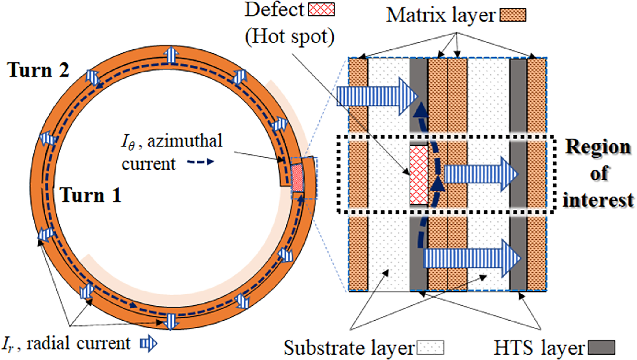
Top view of a defect and the next turn of a REBCO NI pancake coil. The turn before the defect is defined as Turn 1, and the turn after the defect is Turn 2. The net current is assumed to flow from Turn 1 to Turn 2 through azimuthal direction or radial direction.
Fig. 2.

The equivalent circuit based on the actual path of the model described in Fig. 1.
B. Analysis of the Defect Model
In this analysis, we define: the conductor width, w; the matrix thickness δm; the substrate (Hastelloy) thickness δhas; the defect length in the coil ldef; and the length of the turn with defect lturn. The resistance of the radial (Rr) and azimuthal direction (Rθ) can be calculated as
| (1) |
where Rc is the coil contact resistivity, and ρm is the resistivity of the matrix. Note that the Rc value varies with contact surface [9], material [10], [11], pressure [12], [13], coil geometry, [14] and operation cyle [15]. In this research, the Rc value is assumed to be an experimentally measured constant.
Since only the ROI region contributes heating, the heat inside the ROI, Q, can be calculated as
| (2) |
where Iθ is the azimuthal current, Ir is the radial current, and the Iop is the operation current.
The heat capacity of the ROI can be calculated as
| (3) |
If we define an equivalent resistance as
| (4) |
and the equivalent volumetric heat capacity of the ROI as
| (5) |
where Ceq is the equivalent volumetric heat capacity, Cm is the matrix heat capacity, and Chas the substrate heat capacity. The heat equilibrium equation can be written as
| (6) |
where τ0 is the start time of defect appearance, τf is the elapsed time, T0 is the initial temperature of the ROI, and Tf is the final temperature of the ROI. If we define a zeta-function
| (7) |
the time taken to reach the temperature of the ROI from T0 to Tf can be calculated as
| (8) |
Based on this ζ-function, we can estimate the maximum current density or the given NI HTS coil with some specified conditions.
III. Model Validation with Experiment
A. Overview of The Experiment
A radial direction Normal Zone Propagation (NZP) Velocity, VRNZP of an NI HTS coil under the adiabatic condition can be estimated as
| (9) |
Once we charge up the HTS coil over the critical current, the operation current bypass through turn-to-turn, as a result, the magnet field constant will decrease because the equivalent number of turns in the coil will decrease as the turn-to-turn bypassing current [16]. If the cooling is enough to suppress the heat generated by the bypassing current, we can charge up the coil without entering a full quench state or burn-out. However, the equivalent number of turns inside the coil will continuously decrease due to the increasing field. Fig. 3 (a) shows the schematic of the NI HTS coil over-current charging experiment. Since the inner parts of the coil has lower critical current than the outer parts of the coil, we can assume that the current bypassing turns are moving outwards as the operating current is increasing. Once the cooling is enough, the NZP mostly depends on the operation current. However, if the cooling is not enough so close to the adiabatic condition, the heat generated from the bypassing current will trigger additional NZP as described in Fig. 3 (b). The nitrogen bubble trapped below the coil acted like a thermal insulator in this experiment. As a result, a semi-adiabatic environment was created. We can estimate the radial velocity of this additional NZP from (9). Then we can calculate the equivalent number of turns of the coil by using the result.
Fig. 3.

Conceptual schematics of the first (Exp. 1) and the second (Exp. 2) experiments. (a) is the Exp. 1 without NZP, (b) is the Exp. 2 with NZP due to poor cooling condition.
B. Sample Coil Preparation
A sample NI HTS double pancake coil is prepared for the experiment. Table I shows the coil information. The coil is wound as a double pancake with a single inner joint. The top pancake and the bottom pancake is jointed with a 12 mm tape about 60 mm in parallel direction. Fig. 4 shows the prepared coil. A hall sensor is attached at the center of the coil. Three voltage taps are attached to the sample. The inlet of the top pancake, at the stainless steel bobbin for the center, and the outlet of the bottom pancake. A Styrofoam cover is used to create the semi-adiabatic condition by suppressing the free flow of LN2. Fig. 4 (a) shows the coil without the styrofoam cover and Fig. 4 (b) shows the coil with the styrofoam cover.
TABLE I.
NI HTS coil Properties
| Parameters | Value |
|---|---|
| Conductor width | 6 mm |
| Substrate thickness | 50 μm |
| Matrix thickness | 5 μm |
| Self-field critical current (at LN2) | 329 A |
| Coil critical current (at LN2) | 58 A |
| Number of turns per pancake | 254 |
| Coil inner diameter | 22.23 mm |
| Coil outer diameter | 50.15 mm |
| aCoil inductance | 7.6 mH |
| bCharacteristic resistance | 2.1 mΩ |
Calculated value.
Experimentally measured.
Fig. 4.

The NI HTS sample coil used for the experiment. (a) is without hall sensor and Styrofoam cover, (b) is with the hall sensor and Styrofoam cover.
C. The First Experiment and Simulation
The coil is charged up to 125 A with a free LN2 flow at the first experiment (Exp. 1) described in Fig. 3 (a). The blue square dashed line in Fig. 5 shows the field measurement result of the experiment. The operation current gradually increased over the critical current of the coil. The equivalent number of turns in the NI HTS coil decreased from the inner side of the coil as increasing the operating current. In the first simulation (Sim. 1), the behavior of the equivalent number of turns in the coil is calculated based on the Exp. 1 result. According to the voltage measurement result shown in Fig. 6, the equivalent number of turns are assumed to be identical in the top and the bottom pancakes.
Fig. 5.

The measured center field of Exp. 1 and the first simulation (Sim.1) based on the Exp. 1. The non-linear field to operation current characteristic, which is common in an over current operation of the NI coil, is observed.
Fig. 6.

The top and the bottom pancake voltages of Exp. 1 and The equivalent number of turns calculated in Sim. 1. The equivalent number of turns gradually decreased as increasing the operation current. The equivalent number of turns are assumed identical in the top and the bottom pancakes based on the measured voltage result.
D. The Second Experiment and Simulation
The coil is charged up to 125 A again at the second experiment (Exp. 2). The bottom became semi-adiabatic condition as described in Fig. 3 (b). Fig. 8 shows the measurement and the simulation results. Based on the field drop and rapid increasing of the voltage during Exp. 2, the semi-adiabatic NZP started at the bottom pancake, from 121.6 A. From this point, the adiabatic NZP velocity using (9) is applied to calculate the equivalent number of turns in the bottom pancake in the second simulation (Sim. 2). The starting point of the semi-adiabatic NZP is 7.2 mm from the inner diameter (131 turns). The critical current at the point is 129.8 A [17]. which lead to the temperature margin of 1 K, with 93 K of Tc0 and 77 K of the operating temperature. The defective length is the same as the defective turn length, which is 11.5 cm. Based on these parameters, the calculated NZP velocity 82 μm/s. Sim. 1 result and the NZP velocity calculation is combined in Sim. 2. As the NZP increased in the bottom pancake, the field decreased more than Sim. 1 result. The field drop stopped when the equivalent turns in the bottom pancake. The Sim. 2 result, based on the suggested model, is acceptably matched with Exp. 2.
Fig. 8.

The top and the bottom pancake voltages of Exp. 2 and the second simulation (Sim.2). The adiabatic NZP portion is added to the Sim. 1 result based on the NZP velocity calculation.
IV. Maximum Current Density Estimation
One of the most important applications of the model is estimating the maximum current density calculation of the NI coil. Fig. 9 shows one example calculation result with respect to the current density and various Rc values, based on the parameters in Table II. We can estimate the maximum current density with given parameters and time from the calculation result. Here is an example. If the system can hold 1 s until the temperature rises from 4 K to 300 K, the maximum current density of an insulated coil is 155 A/mm2. However, if the contact resistance varied to 500 μΩ·cm2, the maximum current density will increase up to 908 A/mm2.
Fig. 9.

The time taken to reach hot spot temperature from 4 K to 300 K with respect to the overall current density, in given condition. The defect length is 2 mm, the turn length is 100 mm, tape width is 6 mm. This graph varies with the given condition.
TABLE II.
Example case parameters
| Parameters | Value |
|---|---|
| Conductor width | 6 mm |
| Substrate thickness | 50 μm |
| Matrix thickness | 5 μm |
| Expected defect length | 2 mm |
| The length of defect turn | 100 mm |
| Operating temperature | 4 K |
| Maximum allowable temperature | 300 K |
V. Conclusion
We have introduced a new modeling method for the REBCO NI coil. The suggested modeling method is validated by a small coil test. The simulation result based on the NZP velocity calculation using the model and the experiment result are reasonably agreed. We have also introduced the maximum current density estimation as one of the important applications of the modeling method. We can derive the maximum operation current from the suggested model with the given NI HTS coil operation condition. Because of the multiple parameters in the model, the effect of the parameter change, such as the matrix layer thickness or the contact resistance, should be investigated further in the future studies.
Fig. 7.

The measured center field of Exp. 1 and the equivalent number of turns calculated in Sim.2. A rapid increasing voltage of the bottom pancake observed from 1220 s, which is the starting point of the semi-adiabatic NZP. The equivalent number of turns of the bottom pancake additionally decreased as calculated from semi-adiabatic NZP velocity in Sim. 2.
Acknowledgments
The research reported in this publication was supported by the National Institute of General Medical Sciences of the National Institutes of Health under award number R21GM129688.
Contributor Information
Yoonhyuck Choi, MIT Francis Bitter Magnet Laboratory when this work was still going on, is now with Facility for Rare Isotope Beams, Michigan State University, East Lansing, MI 48824, USA..
Yi Li, MIT Francis Bitter Magnet Laboratory when this work was still going on, is now with Department of Mechanical Engineering, Advanced Manufacturing Institute, Texas Center for Superconductivity, University of Houston, Houston, TX 77204, USA..
References
- [1].Hahn S, Park D, Bascuñán J, and Iwasa Y, “HTS Pancake Coils Without Turn-to-Turn Insulation,” IEEE Trans. Appl. Supercond, vol. 21, no. 3, pp. 1592–1595, 2010. [DOI] [PMC free article] [PubMed] [Google Scholar]
- [2].Hahn S, Kim K, Kim K, Hu X, Painter T, Dixon I, Kim S, Bhattarai KR, Noguchi S, Jaroszynski J et al. , “45.5-tesla direct-current magnetic field generated with a high-temperature superconducting magnet,” Nature, vol. 570, no. 7762, pp. 496–499, 2019. [DOI] [PubMed] [Google Scholar]
- [3].Weijers HW, Markiewicz WD, Gavrilin AV, Voran AJ, Viouchkov YL, Gundlach SR, Noyes PD, Abraimov DV, Bai H, Hannahs ST, and Murphy TP, “Progress in the Development and Construction of a 32-T Superconducting Magnet,” IEEE Trans. Appl. Supercond, vol. 26, no. 4, 2016, Art. no. 4300807. [Google Scholar]
- [4].Michael PC, Park D, Choi YH, Lee J, Li Y, Bascuñán J, Noguchi S, Hahn S, and Iwasa Y, “Assembly and Test of a 3-Nested-Coil 800-MHz REBCO Insert (H800) for the MIT 1.3 GHz LTS/HTS NMR Magnet,” IEEE Trans. Appl. Supercond, vol. 29, no. 5, 2019, Art. no. 4300706. [DOI] [PMC free article] [PubMed] [Google Scholar]
- [5].Kubiczek K, Grilli F, Kario A, Godfrin A, Zermeño VMR, Stępień M, and Kampik M, “Length Uniformity of the Angular Dependences of Ic and n of Commercial REBCO Tapes with Artificial Pinning at 77 K,” IEEE Trans. Appl. Supercond, vol. 29, no. 1, 2019, Art. no. 8000309. [Google Scholar]
- [6].Cho M, Noguchi S, Bang J, Kim J, Bong U, Lee JT, An SB, Bhattarai KR, Kim K, Kim K et al. , “Combined Circuit Model to Simulate Post-Quench Behaviors of No-Insulation HTS Coil,” IEEE Trans. Appl. Supercond, vol. 29, no. 5, 2019, Art. no. 4901605. [Google Scholar]
- [7].Oki T, Ikeda A, Wang T, Ishiyama A, Noguchi S, Monma K, Watanabe T, and Nagaya S, “Evaluation on quench protection for no-insulation rebco pancake coil,” IEEE Trans. Appl. Supercond, vol. 26, no. 4, 2016, Art. no. 4702905. [Google Scholar]
- [8].Wang Y, Chan WK, and Schwartz J, “Self-protection mechanisms in no-insulation (RE)Ba2Cu3Ox high temperature superconductor pancake coils,” Supercond. Sci. Technol, vol. 29, no. 4, March. 2016, Art. no. 045007. [Google Scholar]
- [9].Jeon H, Lee WS, Kim J, Baek G, Jeon S, Yoon YS, and Ko TK, “Investigation of electrical characteristics of no-insulation coil wound with surface-processed HTS tape,” Physica C, vol. 539, pp. 25 – 29, 2017. [Online]. Available: http://www.sciencedirect.com/science/article/pii/S0921453417300679 [Google Scholar]
- [10].Sohn M, Sim K, Eom B, Ha H, Kim H, and Seong K, “Controllability of the Contact Resistance of 2G HTS Coil With Metal Insulation,” IEEE Trans. Appl. Supercond, vol. 28, no. 3, 2018, Art. no. 4602705. [Google Scholar]
- [11].Lee TS, Hwang YJ, Lee J, Lee WS, Kim J, Song SH, Ahn MC, and Ko TK, “The effects of co-wound Kapton, stainless steel and copper, in comparison with no insulation, on the time constant and stability of GdBCO pancake coils,” Supercond. Sci. Technol, vol. 27, no. 6, 2014, Art. no. 065018. [Google Scholar]
- [12].Bonura M, Barth C, Joudrier A, Troitino JF, Fête A, and Senatore C, “Systematic Study of the Contact Resistance Between REBCO Tapes: Pressure Dependence in the Case of No-Insulation, Metal Co-Winding and Metal-Insulation,” IEEE Trans. Appl. Supercond, vol. 29, no. 5, 2019, Art. no. 6600305. [Google Scholar]
- [13].Kim KL, Hahn S, Kim Y, Yang DG, Song J-B, Bascuñán J, Lee H, and Iwasa Y, “Effect of Winding Tension on Electrical Behaviors of a No-Insulation ReBCO Pancake Coil,” IEEE Trans. Appl. Supercond, vol. 24, no. 3, 2013, Art. no. 4600605. [DOI] [PMC free article] [PubMed] [Google Scholar]
- [14].Wang Y and Song H, “Influence of turn-to-turn resistivity and coil geometrical size on charging characteristics of no-electrical-insulation REBCO pancake coils,” Supercond. Sci. Technol, vol. 29, no. 7, 2016, Art. no. 075006. [Google Scholar]
- [15].Lu J, Goddard R, Han K, and Hahn S, “Contact Resistance Between Two REBCO Tapes Under Load and Load Cycles,” Supercond. Sci. Technol, vol. 30, no. 4, February. 2017, Art. no. 045005. [Google Scholar]
- [16].Choi S, Jo HC, Hwang YJ, Hahn S, and Ko TK, “A Study on the No Insulation Winding Method of the HTS Coil,” IEEE Trans. Appl. Supercond, vol. 22, no. 3, 2012, Art. no. 4904004. [Google Scholar]
- [17].Zhang X, Zhong Z, Geng J, Shen B, Ma J, Li C, Zhang H, Dong Q, and Coombs T, “Study of Critical Current and n-Values of 2G HTS Tapes: Their Magnetic Field-Angular Dependence,” J. Supercond. Nov. Magn, vol. 31, no. 12, pp. 3847–3854, 2018. [Google Scholar]